Table of Contents
Advertisement
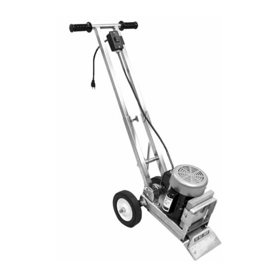
#505 PANTHER
®
PLUS
FLOOR
STRIPPER
INSTRUCTION MANUAL
READ MANUAL BEFORE OPERATING MACHINE
National
Flooring Equipment, Inc.
9250 X
A
N
• M
, MN 55445 • U.S.A.
YLON
VENUE
ORTH
INNEAPOLIS
800-245-0267 • 763-535-8206 • F
763-535-8255 • F
800-648-7124
AX
AX
W
S
: www.nationalequipment.com • E-M
: info@nationalequipment.com
EB
ITE
AIL
Advertisement
Table of Contents

Related Manuals for National 505 PANTHER PLUS


Summary of Contents for National 505 PANTHER PLUS
- Page 1 #505 PANTHER ® PLUS FLOOR STRIPPER INSTRUCTION MANUAL READ MANUAL BEFORE OPERATING MACHINE National Flooring Equipment, Inc. 9250 X • M , MN 55445 • U.S.A. YLON VENUE ORTH INNEAPOLIS 800-245-0267 • 763-535-8206 • F 763-535-8255 • F 800-648-7124 : www.nationalequipment.com • E-M...
-
Page 2: Table Of Contents
TABLE OF CONTENTS Table of Contents ......................2 Rules for Safe Operation..................3-6 A. Grounding ......................5 B. Extension Cords ....................6 General Operation....................7-10 A. Assembly ......................7-8 B. Wheel Adjustment ....................8 C. Handle Adjustment ....................9 D. Machine Operation ....................9 E. Machine Start Up Procedure ................9 F. -
Page 3: Rules For Safe Operation
USE” until repaired. A guard or other damaged parts should be properly repaired or replaced. For all repairs, insist on only identical National replacement parts. 11. REMOVE ALL ADJUSTING KEYS AND WRENCHES: Make a habit of checking that the adjusting keys, wrenches, etc. - Page 4 23. STORE IDLE TOOLS: When not in use, store your tool in a dry, secured place. Keep out of reach of children. 24. MAINTAIN LABELS AND NAMEPLATES: These carry important information. If unreadable or missing, contact National for a free replacement. 25. MACHINE IS HEAVY, DO NOT DROP: Counter weights are heavy. Take caution when removing or reassembling.
-
Page 5: Grounding
RULES FOR SAFE OPERATION GROUNDING WARNING: Improperly connecting the grounding wire can result in the risk of electric shock. Check with a qualified electrician if you are in doubt as to whether the outlet is properly grounded. Do not modify the plug provided with the tool. Never remove the grounding prong from the plug. Do not use the tool if the cord or plug is damaged. -
Page 6: Extension Cords
RULES FOR SAFE OPERATION EXTENSION CORDS WARNING: Electrical cords can be hazardous. Misuse can result in fire or death by electrical shock. Read carefully and follow all directions. Grounded tools require a three wire extension cord. Double insulated tools can use either a two or three wire extension cord. -
Page 7: General Operation
GENERAL OPERATION ASSEMBLY THE PANTHER COMES DISASSEMBLED. 1. Slide switch onto handle leg with switch to the inside of handle (See Figure A). 2. Loosen the top two T-bolts on the handle frame. 3. Insert handle into handle frame (See Figure A) and adjust to desired height 4. -
Page 8: Wheel Adjustment
GENERAL OPERATION ASSEMBLY (continued) FOR SHIPPING, WHEEL ADJUSTMENT PINS ARE NOT INSERTED CORRECTLY THROUGH HANDLE FRAME. 1. Remove handle adjustment pins (See Figure A). It may be necessary to maneuver handle so it is not touching the handle adjustment pins. OR, lay machine onto side (See Figure B). 2. -
Page 9: Handle Adjustment
GENERAL OPERATION HANDLE ADJUSTMENT AFTER THE PROPER WHEEL ADJUSTMENT IS ACHIEVED, ADJUST HANDLE BY EITHER A OR B: A. Removing handle adjustment pins, adjust handle to proper angle and reinsert handle adjustment pins. B. Lay machine on side, remove handle adjustment pins, adjust handle to proper angle and reinsert handle adjustment pins. -
Page 10: Transportation
GENERAL OPERATION USER GENERAL INFORMATION (continued) 12. Dropping machine onto cutting head could cause damage to blade holder and cause undue wear on bearing surface. 13. Removable handle and front weight makes machine portable (fits in a trunk of a car). 14. -
Page 11: Blades
• A new sharp blade being used on wood or alike sub floors may work better when slightly dulled to avoid digging or gouging. • Use National Flooring Equipment’s replacement blades. BLADE SETTING • Dull blades greatly reduce cutting ability. Re-sharpen or replace as needed. - Page 12 BLADES BLADE SETTING (continued) • Wood or wood like floors: pound down or remove any nails or metal obstruction to avoid blade damage. • Blades can be offset in cutting head for easier access to toe kicks or removal along the wall (See Figure •...
-
Page 13: Types Of Tearouts
BLADES TYPES OF TEAROUTS REMOVAL MATERIALS WARNING: Never remove flooring containing asbestos without fully understanding proper state and federal procedures and guidelines. • VCT TILE: Never use a blade wider than the size of the tile being removed (See Figure A). If goods being removed still do not come up clean or machine jumps on top of goods, reduce blade size to a smaller blade until proper blade size is found or use a smaller portion of the blade. - Page 14 BLADES TYPES OF TEAROUTS (continued) SUBFLOOR SURFACES • WOOD: When working over plywood sub-flooring, try to run machine in the same direction as the grain in the wood. Blade in most cases should be bevel down. On solid wood floors, like plank, run in the same direction as the plank, not cross grain or cross plank.
-
Page 15: Blade Diagram
BLADES BLADE DIAGRAM Double Edge Sharp .062 Sharp .062 .094 Heavy Duty .062 .250 Standard Extra Heavy Duty Self-Scoring Corner .187 .062 #502 Ripper Teeth For difficult surfaces; Double Ground Stripper ceramic, hardwood, heavy *Add symbol “D” to stock number for double ground. tile, etc. -
Page 16: Blade Chart
BLADES Part # Description Application Thickness #130-S 3'' x 10'' Blade with slots glued down carpet, tile or resilient .062 #130-D #130 Blade with both edges sharpened carpet, tile or resilient on wood & concrete floors .062 #131-S 3'' x 16'' Blade with slots glued down rubber carpet, floor accumulation .062 #135... -
Page 17: Maintenance
REPAIRS If your tool is damaged, contact National for a return authorization number and return the entire tool. • Shipments are not accepted without a return authorization number. • COD or freight collect shipments will not be accepted. -
Page 18: Troubleshooting
TROUBLESHOOTING THERE IS NO POWER 1. Inspect electrical cord. MOTOR NOISE 1. Make sure fan guard is not bent. RATTLING 1. Tighten loose nuts and bolts. MACHINE IS HARD TO HANDLE 1. Remove the counterweight. 2. Change to a smaller blade. 3. -
Page 19: Complete Parts List
COMPLETE PARTS LIST PART # DESCRIPTION 500-10 COVER PLATE ONLY 500-12 PLUG CORD SET ONLY 500-13 SWITCH BOX ONLY 500-14 WIRE STRAIN RELIEF (3) 500-15 HANDLE GRIPS ONLY (EACH) 500-16L HANDLE SUPPORT LEGS (LEFT) 500-16R HANDLE SUPPORT LEGS (RIGHT) 500-19 BLADE COVER 500-25 WHEEL LEG (2) - Page 20 COMPLETE PARTS LIST LABEL LIST PART # DESCRIPTION BLADE SETTING LABEL CAUTION SHARP BLADES LABEL DISCONNECT POWER LABEL CAUTION CORD LABEL L175 NATIONAL LABEL - SMALL L189 SAFE OPERATING TIPS LABEL Page 20...
-
Page 21: Part Numbers And Diagrams
PART NUMBERS & DIAGRAMS PART # DESCRIPTION PART # DESCRIPTION 500-33 Adjustment T Bar Sleeve 500-10 Cover Plate Only 500-12 Plug Cord Set Only Weight Attachment 500-13 Switch Box Only 503-1 Weight Clip w/Bolt (2) 500-14 Wire Strain Relief (3) 505-38 Base Weldment 500-15... -
Page 22: Internal Parts
PART NUMBERS & DIAGRAMS WHEEL PARTS PART # DESCRIPTION 500-25 Wheel Leg (2) 500-25 500-29 Wheel (2) 500-30 Wheel Axle 500-30A O Rings (2) 73402 1/2-13 Nylon Lock Nut (2) 73404 73407 73402 73404 500-30A 500-29 73404 1/2 Flat Washer (4) 73407 1/2-13 x 1-1/2 Hexhead Bolt (2) 500-25... - Page 23 PART NUMBERS & DIAGRAMS 6280-133 6280-133 73309 73309 505-1000 73211 73211 73322 73322 505-101 73902 73073 73074 71118 73201 73309 73309 73322 73322 73211 6280-133 73211 6280-133 73215 505-1001 PART # DESCRIPTION PART # DESCRIPTION 505-101 Eccentric 73201 3/8-16 x 1-1/4 Hexhead Bolt (2) 505-1000 Bottom Plate 73211...
-
Page 24: Labels
LABELS L189 L175 LABEL LIST PART # DESCRIPTION Blade Setting Label Caution Sharp Blades Label Disconnect Power Label Caution Cord Label L175 National Label - Small L189 Safe Operating Tips Label Page 23... -
Page 25: Guarantee
In no event shall National be liable, or in any way responsible for any damage or defects in the product which were caused by repairs or attempted repairs performed by anyone other than National. Nor shall National be liable, or in any way responsible, for any incidental or consequential, economics or property damage. -
Page 26: Return Sheet
Telephone Number Approximate Usage (hours) Problems Encountered Check One: Repair Do you wish to be contacted before repairing Return Contact National if a loaner is needed Return Authorization Number Date required, contact National Customer Number if known Purchased From if not directly from National... - Page 27 3'' x 8'' Increased Angle Blade .062 All orders and payment terms to be verified prior to shipping. National Flooring Equipment, Inc. 9250 Xylon Avenue • Minneapolis, MN 55445 800-245-0267 or 763-535-8206 • Fax 800-648-7124 or 763-535-8255 Web Site: www.nationalequipment.com E-Mail: info@nationalequipment.com...
Need help?
Do you have a question about the 505 PANTHER PLUS and is the answer not in the manual?
Questions and answers