Table of Contents
Advertisement
Advertisement
Table of Contents

Related Manuals for Amico ice 30m

Summary of Contents for Amico ice 30m
- Page 1 Installation and Operation Instructions Surgical Lights w w w . a m i c o . c o m...
-
Page 2: Table Of Contents
Installation: The Central Axis 19-21 Installing the Ceiling Cover (Series 1) Installing the Ceiling Cover (Series 3) Amico Ceiling Covers - Square Ceiling Covers Option for Both Series 1 and Series 3 Installing the Central Axis 20-21 Installation: Electrical 22-23... -
Page 3: Amico Ceiling Covers - Square Ceiling Covers Option For Both Series 1 And Series
Wall Control Panel for Light (only if purchased) Camera Control Box (Camera Adder Only) Automatic Emergency Backup Board Beam Size Adjustment 45-46 Operation: Cleaning the Amico iCE 30m LED Light 47-48 Non-Sterilizable Handle (Plastic/Aluminum) Smart Handle (option available) Lamp Housing, Protective Lens and Support System... -
Page 4: Introduction
• User has to be able to position the iCE 30m Light by holding the light through the openings. Intended Use: • The iCE 30m LED Surgical Lightning System is designed to illuminate the surgical field with a cool, bring white light and an adjustable pattern size. -
Page 5: Symbols Used In This Manual
Caution - Risk of danger Certified by TUV ISO-7010-M002 Refer to instruction manual/booklet MARKINGS The iCE 30m LED Series Surgical Lights are designed to comply with the following Standards: IEC 60601‐1 edition 3.1 Standard(s): CAN/CSA‐C22.2 No. 60601‐1 ANSI/AAMI ES60601‐1 IEC 60601‐1‐6 IEC 60601‐2‐41... -
Page 6: Typical Drawings
Typical Drawings Single Ceiling Mount Single Ceiling Mount for Low Ceiling Height Dual Ceiling Mount... - Page 7 Typical Drawings Dual Ceiling Mount with Monitor Range of Motion for Dual Ceiling Mount www.amico.com...
-
Page 8: Technical Data For Ice Lightheads
Never combine beams from more than two lampheads, as the resulting irradiance at the spot can exceed 1000 W/m² resulting in a higher than normal temperature. Upon request, Amico Clinical will make available the circuit board diagrams, component parts list, descriptions, calibration instructions or other information that will assist service personnel in conducting repairs to the iCE 30m. -
Page 9: Installation Considerations
Installation Considerations • All Amico lamps are supplied with a flange with a graduated circle diameter of 310 mm (12.2") and six bores with a diameter of 17 mm (0.67"). The flange supports the vertical suspension tube. It is attached to the solid ceiling by means of a ceiling anchorage ring. -
Page 10: Tools And Part Requirements
Safety Instructions STORAGE AND USAGE HAZARD • Store the iCE 30m LED Series Surgical Light in its package for at least 24 hours in the respective room before mounting, in order to equalize temperature differences. • Make sure that the light is in perfect working order before every use. - Page 11 If the focusing light handle (metal/plastic, provided with lighthead) is used without a disposable cover, the handle is not protected by a sterile covering. • Sterilizable handles are available through Amico Clinical Solutions Corp. DISPOSAL HAZARD This product contains materials which may require disposal through appropriately licensed and permitted hazardous waste management firms.
- Page 12 • During all mounting steps, verify that wires are not pinched between spring arms or lightheads. • Avoid cross-threading brake screws, align them with extreme care. • Accessories or replacement parts not purchased from Amico are not to be used as they may negatively affect the equipment or result in equipment damage.
-
Page 13: Static Inspection
It is hereby certified that the support ceiling and the ceiling anchoring is safe and adequately strong. Project: Anchoring (please check the applicable selection): With anchors/rods authorized by the structural engineer/construction authority With a counter-plate Other: Location: Signature/Stamp of Structural Engineer/Construction Authority: www.amico.com... -
Page 14: Components And Scope Of Delivery
SURFACE FINISH 63 uin PRODUCTION : __________________________ THIS PRINT IS PROPERTY OF AMICO CLINICAL AND IS LOANED IN CONFIDENCE SUBJECT TO RETURN UPON BREAK ALL EDGES 0.005 - 0.010 REQUEST AND WITH THE UNDERSTANDING THAT NO COPIES ARE TO BE MADE WITHOUT THE CONSENT OF REMOVE SHARP EDGES AND BURRS •... -
Page 15: Installation: Structure Plates And Flanged Ceiling Tube
Installation: Structure Plates and Flanged Ceiling Tube Structure Plate and Anchor Plate Dual Mount 540mm 540mm [21.260"] [21.260"] Single Mount Legend M16 clearence hole M16 clearence hole M10 clearence hole *Hole markings for representation purpose only www.amico.com... -
Page 16: Order Components For Each Threaded Rod
• 1 x Hex Nut • 1 x Hex Nut • 1 x Lock Washer • 1 x Flat Washer • Anchor Plate • 1 x Flat Washer • 1 x Lock Washer • 2 x Hex Nuts Amico Clinical Solutions Corp. -
Page 17: Installing The Flanged Ceiling Tube (Series 1)
KED BY: This Series includes: X.XXXX .0005 One center drop tube and up to two satellite arms Up to 4 extension arms Maximum length arms on center tube: 1750mm, 1600mm, 1450mm Maximum length arms on the satellite arms: 1750mm www.amico.com... - Page 18 6. Align the flanged ceiling tube horizontally by adjusting the M16 hex nuts. Check the horizontal alignment. WARNING – Risk of Pendant System dropping: Tighten the M16 hex nuts to 75 lbs-ft (torque). 7. Check that the flanged ceiling tube is securely in place. Amico Clinical Solutions Corp.
-
Page 19: Installation: The Central Axis
M10 rods. Thread the screws through the screw caps, through the bottom of the Series Three circular ceiling cover and into the bottom of the M10 rods to keep the Series Three circular ceiling cover in place. www.amico.com... -
Page 20: Installing The Central Axis
Installation: The Central Axis Amico Ceiling Covers - Square Ceiling Covers Option for Both Series One and Series Three 1. Insert an M10 rod into the six smaller outer holes in anchor plates using a M10 nut on either side of the bottom anchor plate to keep them from moving up and down. - Page 21 2. Install using the 2 x ¼-20 button head screws with a ¼" washer as shown in the image. 3. Finish the installation using the 4 x ¼-20 socket cap screws with ¼" washers through the angled holes. www.amico.com...
-
Page 22: Installation: Electrical
[D] with gentle force. [A] Extension Leads • For extension arms without stop: route the [D] Flanged Ceiling Tube extension leads [A] through the flanged ceiling tube [D] to the interface plate [A]. Amico Clinical Solutions Corp. -
Page 23: Routing The Supply Lines Through The Ceiling Tube
1. All conductors must be secured to the interface plate using the strain relief. 2. Feed the power supply leads through the strain relief. 3. Connect the power supply lines to the terminal block, as shown in pages 40-42. www.amico.com... -
Page 24: Installation: Spring Arms
• The pendant system central axis and the mounted spring arms are not intended for operation in potentially explosive atmospheres. • The pendant system central axis is suitable for continuous operation. • The ID plate can be found on the top extension arm. Amico Clinical Solutions Corp. - Page 25 Installation: Spring Arms Standard Spring Arms on the Central Axis - Series Three The following diagram illustrates possible spring arm configurations. 10" [254mm] 25.3" [643mm] 16" [402mm] 45° 17.9" [454mm] 45.3" 39.4" 45° 16.1" 32.7" 25.3" [410mm] [644mm] 27.6" www.amico.com...
-
Page 26: Initial Setup
3. On the top side of the adaptor weld, put two spacer shims onto the extruding rear weld tube. Amico Clinical Solutions Corp. - Page 27 4. Clip the front plastic cover pieces together and secure them in place using two M4-6 screws on either side. 5. Replace the plastic cover caps by pressing inwards and turning. Ensure that any labeling is positioned right side up. www.amico.com...
-
Page 28: Removing The Safety Plug
3. Using a small flat head screwdriver, remove the Cotter pin [2] from the groove in the device end stem. 4. Once the locking key has been removed, slide the safety plug out from the lighthead end of the spring arm. Item Description Cotter Holder Cotter Pin Cotter Holder Cover M3 Screw Groove Amico Clinical Solutions Corp. -
Page 29: Installation: Amico Ice 30M Led Light
Installation: Amico iCE 30m LED Light Installing the iCE 30m Lighthead Regular Spring arms Only 1. Insert the cotter holder onto the front weld tube with the cutout closer to the ground. 2. Monitor Spring Arms will have a ring stop inserted into the bottom of the front weld tube with the extruding tooth facing downwards. - Page 30 Installation and removal for service or inspection must be carried out by a hospital technician or a person with similar qualifications who has been trained by Amico Clinical Solutions Corp. • Never perform an installation or removal of the LED light alone. Always have a second person to assist with the installation or removal.
- Page 31 Installation: Amico iCE 30m LED Light 1. Install the 3 x M6 -12 mm set screw. Tighten evenly and proportional to each other (step by step) so that there is even pressure on the yoke from all sides. 2. Install the cover from Step 1 to complete the light installation and install the 2 x M3 screws.
-
Page 32: Normal System/Lch With Camera
Installation: Amico iCE 30m LED Light Normal System/LCH with Camera 1. Ensure 9-pole slip ring is removed from the light head. 2. Ensure the unit is disconnected from the power supply, with no possible accidental reconnection. 3. Install light head as a normal light head. - Page 33 Installation: Amico iCE LED Light 6. Connect the 9-pole slip ring to cable by joining the connectors and ensuring they are secure. 9-pole slip ring 7. Push the cables into the yoke axle as seen below and insert screws to keep in place.
-
Page 34: Touch Handle Servicing
Installation: Amico iCE 30m LED Light Touch Handle Servicing Follow the steps below whenever a Touch Handle needs to be serviced. 1. Remove the Light Handle by pressing in the pins and pulling the Handle off. 2. Use a 1/16” Allen Key to loosen the set screw holding the Touch Handle. -
Page 35: Installing In Light Camera (Optional Accessory)
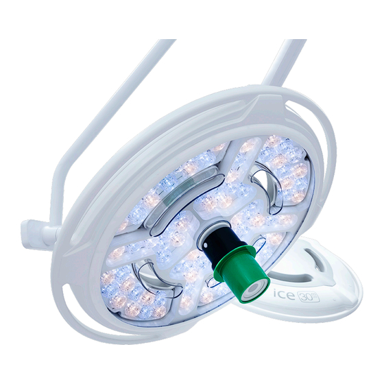
Installation: Amico iCE LED Light Installing in Light Camera (Optional Accessory) 1. Connect the Lemo Connector to the camera. Connector Jacket Release Release Button Button 2. Install camera on light. 3. In order to remove the camera press the two release buttons highlighted by the arrows above. -
Page 36: Installation: Adjustments
To adjust the height, use a 5mm T-handle through the front and turn: 1. Clockwise to limit the height. 2. Counterclockwise to allow for maximum height. Add screws to limit the LCH spring arm height. Use a 5mm T-handle to limit the height. Amico Clinical Solutions Corp. -
Page 37: Installation/Removal Of The Spring Arm
6. Leave the flap covers extended and raise the spring arm to its highest and lowest positions and slide each flap into its groove when all other plastic covers have been assembled. Description Item Plug Covers Spring Arm Main Covers Screws Sliding Flap Covers www.amico.com... -
Page 38: Load Adjustment
Components inside will move when spring arm is moved up or down. Do not insert fingers or tools into the load adjustment window when the spring arm is moving. Amico Clinical Solutions Corp. -
Page 39: Installation: The Base Cap
2. Align the locking tooth into one of the notches in the nut at the bottom of the central axis. 3. Press the cover up until it bottoms against the nut. Lightly tighten the three set screws equally, until the cover is snug and secure. Central Axis Base Cap www.amico.com... -
Page 40: Installation: Terminal Box
Flanged Drop Tube using two M4 screws with washers (circled in figure 2). 2. Connect all wire harnesses per configuration. 3. Use cable tie all loose wired together to a structure Figure 1 Figure 2 Part Number Description Quantity FS-SCR-SC-M4-22-SS M4X0.7-22 Socket Cap Screw FS-WSH-M4-SS M4 Flat Washer Amico Clinical Solutions Corp. -
Page 41: Connecting The Terminal Box
Installation: Terminal Box The iCE 30m system comes with wire harnesses pre-installed on all related components. Plug in all the required components depending on your configuration. If the power supply is working properly, a green LED should turn on. If there is a fault with the power supply, a red LED would turn on instead. -
Page 42: Pre-Wired Harnesses
• Included in camera adder, camera ready Camera Video/Data Cable Camera In and spring arm camera units • Custom Barrel Connectors Power Pass • Positive Centre; +12VDC Camera Power Cable Through • Included in spring arm camera units Camera cable Amico Clinical Solutions Corp. -
Page 43: Operation: Amico Ice 30M Led Light
Brightness Operation: The Amico iCE 30m LED Light Power Endo 3500 K 4000 K 4500 K 5000 K Color Brightness Pantone Cool Gray 11C - all text Lighthead Control Panel 1. Turning the light ON and OFF: The LED will light up when the lamp is in the ON position. -
Page 44: Camera Control Box (Camera Adder Only)
Operation : The Amico iCE 30m LED Light Camera Control Box Zoom Focus Brightness Rotate Source Power Freeze AUTO AUTO Press to decrease Press to increase brightness brightness Camera Control Box (Camera Adder Only) 1. Pressing the Power button turns the camera On and Off. -
Page 45: Automatic Emergency Backup Board
Beam Size Adjustment Amico iCE 30m Series LED Lights come with a handle for adjusting the beams. By turning the handle, you can either increase or decrease the beam size. This creates a beam ranging from 7.6" - 12" (193 mm - 305 mm). - Page 46 Operation: The Amico iCE 30m LED Light Expanded Beam Amico Clinical Solutions Corp.
-
Page 47: Operation: Cleaning The Amico Ice 30M Led Light
Operation: Cleaning the Amico iCE 30m LED Light Non-Sterilizable Handle (Plastic/Aluminum) 1. At delivery, the lamp is equipped with an aluminum or plastic non-sterilizable handle. This handle must not be sterilized as it will cause damage to the handle. 2. The handles will be supplied with disposable, sterile covers. Handle disposable covers often become unsterile during an operation. -
Page 48: Lamp Housing, Protective Lens And Support System
Operation: Cleaning the Amico iCE 30m LED Light Lamp Housing, Protective Lens and Support System 1. The Amico lamp system has a high-quality surface which can be cleaned with conventional cleaning agents. • Virox Accel TB • Virox 5 • Dispatch Hospital Cleaner disinfectant towels with Bleach •... -
Page 49: Maintenance: Amico Ice 30M Led Lights
Maintenance: Amico iCE 30m LED Lights 1. Amico iCE Series LED Lights are supplied with brakes on the suspension fixture and on the lamp housing. If necessary, adjust these brakes after installation. 2. If the lamp is difficult to move, or if it does not keep its position, the brake forces needs to be adjusted. -
Page 50: Annual Inspection (To Be Completed By Qualified Technicians)
30m Should problems arise with the use of the Amico Series iCE 30m LED Lights, review the following chart. Find the fault and complete the recommended solution. If the fault is not found and or/the solution does not correct the problem contact Amico Clinical Solutions Corp. -
Page 51: Environmental Conditions
Relative atmospheric humidity Air pressure 700 hPa 1060 hPa References on the Package +50 C° 20% - 90% 700hPa - 1060hPa -10 C° Temperature range Atmospheric Air pressure for transport humidity for transport and storage for transport and storage and storage www.amico.com... -
Page 52: Electromagnetic Compliance Data For Ice 30M Series
Electromagnetic Compliance Data for iCE 30m Series Guidance and Manufacturer’s Declaration – Electromagnetic Emissions The equipment or system is intended for use in the electromagnetic environment specified below. The customer or the user of the equipment or system should assure that it is used in such an environment. -
Page 53: Guidance And Manufacturer's Declaration - Electromagnetic Immunity
Electromagnetic Compliance Data for iCE 30m Series Guidance and Manufacturer’s Declaration – Electromagnetic Immunity The equipment or system is intended for use in the electromagnetic environment specified below. The customer or the user of the equipment or system should assure that it is used in such an environment. - Page 54 Electromagnetic Compliance Data for iCE 30m Series Guidance and Manufacturer’s Declaration – Electromagnetic Immunity The ME EQUIPMENT or ME SYSTEM is intended for use in the electromagnetic environment specified below. The customer or the user of the ME EQUIPMENT or ME SYSTEM should assure that it is used in such an environment.
-
Page 55: Recommended Separation Distances Between Portable And Mobile Rf Communications Equipment And The Equipment Or System
Electromagnetic Compliance Data for iCE 30m Series Recommended Separation Distances Between Portable and Mobile RF Communications Equipment and the Equipment or System The equipment or system is intended for use in an electromagnetic environment in which radiated RF disturbances are controlled. The customer or user of the equipment or system can help prevent electromagnetic interference by... -
Page 56: Warranty
HD Cameras, in-light or spring arm mounted, are warrantied for a period of twelve (12) months from date of installation. During this period, Amico Clinical Solutions Corp. will, at its own cost, repair and/or replace any part on site or at the factory which has proven to be defective. - Page 57 Amico Clinical Solutions Corp. | 85 Fulton Way, Richmond Hill, ON L4B 2N4, Canada | 600 Prime Place, Hauppauge, NY 11788, USA Toll Free Phone: 1.877.462.6426 | Toll Free Fax: 1.866.440.4986 | Tel: 905.764.0800 | Fax: 905.764.0862 Email: info@amico.com | www.amico.com...
Need help?
Do you have a question about the ice 30m and is the answer not in the manual?
Questions and answers