Table of Contents
Advertisement
Quick Links
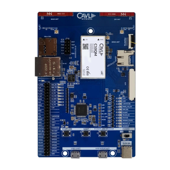
Cavli Wireless C100QM/C10QM Hardware Manual
Cavli C100QM/C10QM
LTE CAT 4/CAT 1/3G/2G
Smart Module
Hardware Manual
Release Version 2.1
www.cavliwireless.com
Copyright © 2019 by Cavli Wireless Inc.
All rights reserved. All document materials, including, without limitation, the logos, design, text, graphics, other files and the selection and
arrangement are copyrighted as otherwise noted on the linked page. No part of this publication may be reproduced, distributed, or transmitted in
any form or by any means, including photocopying, recording, or other electronic or mechanical methods, without the prior written permission of
the publisher, except in the case of brief quotations embodied in critical reviews and certain other noncommercial uses permitted by copyright
1
law. For permission requests, are allowed only for company with registered customer ID within Cavli Wireless. Write to sales@cavliwireless.com
for registering the company.
Cavli Wireless Inc.
177 Park Avenue
San Jose, California, USA 95113
www.cavliwireless.com
Advertisement
Table of Contents

Related Manuals for Cavli Wireless C100QM


Summary of Contents for Cavli Wireless C100QM
- Page 1 For permission requests, are allowed only for company with registered customer ID within Cavli Wireless. Write to sales@cavliwireless.com for registering the company.
- Page 2 Cavli Wireless C100QM/C10QM Hardware Manual Update records Version Date Description Author V2.0 20180126 Initial Simon V2.1 20191111 Manual Update Sony...
-
Page 3: Table Of Contents
Cavli Wireless C100QM/C10QM Hardware Manual Contents Chapter 1. Introduction Chapter 2. Module Overview 2.1 Module introduction 2.2 Module characteristics 2.3 Module function Chapter 3. Interface application description 3.1 Chapter overview 3.2 Module interface 3.2.1 144-pin LCC interface 3.2.2 Interface definition 3.3 Power interface... - Page 4 Cavli Wireless C100QM/C10QM Hardware Manual 3.5 USB interface 3.6 UART interface 3.6.1 Main serial port 3.6.2 Debug serial port 3.6.3 RI and DTR interface 3.7 USIM interface 3.7.1 USIM card reference circuit 3.7.2 UIM_DET Hot Swap Reference Design 3.8 General purpose GPIO interface 3.9 Network status indication interface...
- Page 5 Cavli Wireless C100QM/C10QM Hardware Manual Chapter 4. Overall technical indicators 4.1 Chapter overview 4.2 GNSS reception performance 4.3 working frequency 4.4 Conducted radio frequency measurement 4.4.2 standard test 4.5 Conducted receiving sensitivity and transmit power 4.6 Antenna requirements 4.7 Power consumption characteristics Chapter5.
- Page 6 Cavli Wireless C100QM/C10QM Hardware Manual 7.3 Production welding Chapter 8. Appendix 8.1 Chapter overview 8.2 Abbreviations 8.3 Encoding 8.4 Safety and precautions Figures Contents Chapter 1. Introduction Chapter 2. Module Overview 2.1 Module introduction 2.2 Module characteristics 2.3 Module function Chapter 3.
- Page 7 Cavli Wireless C100QM/C10QM Hardware Manual 3.3.4 VDD_EXT 1V8 voltage output 3.4 Switching machine reset mode 3.4.1 Boot 3.4.2 Boot timing 3.4.3 Power down 3.4.4 Reset control 3.5 USB interface 3.6 UART interface 3.6.1 Main serial port 3.6.2 Debug serial port 3.6.3 RI and DTR interface...
- Page 8 Cavli Wireless C100QM/C10QM Hardware Manual 3.17 RF interface 3.17.1 Main set antenna interface 3.17.2 Diversity antenna interface 3.17.3 GNSS interface 3.17.4 RF trace reference 3.17.5 RF connector size Chapter 4. Overall technical indicators 4.1 Chapter overview 4.2 GNSS reception performance 4.3 working frequency...
- Page 9 Cavli Wireless C100QM/C10QM Hardware Manual 6.1 Chapter overview 6.2 Exterior 6.3 C100QM/C10QM module mechanical size Chapter7. Packaging and production 7.1 Chapter overview 7.2 Module packaging and storage 7.3 Production welding Chapter 8. Appendix 8.1 Chapter overview 8.2 Abbreviations 8.3 Encoding...
-
Page 10: Chapter 1. Introduction
Cavli Wireless C100QM/C10QM Hardware Manual Chapter 1. Introduction This document is a wireless solution product C100QM/C10QM module hardware interface manual, designed to describe the hardware components and functional characteristics of the module solution, application interface definition and use instructions, electrical performance and mechanical characteristics. Combined with this and other... -
Page 11: Chapter 2. Module Overview
Cavli Wireless C100QM/C10QM Hardware Manual Chapter 2. Module Overview 2.1 Module introduction The C100QM/C10QM module is an LCC package module. C100QM is a wireless terminal product that integrates various network standards and GPS positioning services such as FDD-LTE/TDD-LTE/TD-SCDMA/WCDMA/EVDO/CDMA/EDGE/GSM C10QM supports LTE CAT1 and GPS positioning services. C100QM/C10QM module is based on... -
Page 12: Module Characteristics
Cavli Wireless C100QM/C10QM Hardware Manual 2.2 Module characteristics Table 2-1 Module band list Module series Network Type Frequency band C100QM GSM850 √ GSM900 √ GSM1800 √ LTE FDD B1 √ LTE FDD B3 √ LTE FDD B5 √ LTE(FDD) LTE FDD B7 √... - Page 13 ✧ C10QM supports CAT1 standard modules for customer specific applications, 5Mbps for uplink CAT1 and 10Mbps for CAT1 downlink ✧ C100QM Module supports Category 4. When you need to support the Category 1 module, the C10QM CAT1 is printed on the module label. CAT1 does not support diversity.
- Page 14 Cavli Wireless C100QM/C10QM Hardware Manual ✧ Standard Support 3.0V/1.8V, support swap functionUSB2.0 (High-Speed) (only supports slave interface mode), data transfer rate up to 480Mbps For AT commands, data transfer, GNSS NMEA output, software debugging and software upgrades USB driver: Support Windows XP, Windows Vista, ✧...
- Page 15 Cavli Wireless C100QM/C10QM Hardware Manual interface Clock frequency up to 50MHz Maximum capacity supports 32GB Interface voltage domain is 1.8/2.95V, two voltages are adjustable Support 3.3V-4.2V DC power supply ✧ Power interface Used to indicate the status of the module, the speed of the light is on, indicating the status of the module that is not available.
- Page 16 Support LTE diversity antenna AT command Support for standard AT instruction sets (Hayes 3GPP TS 27.007 and 27.005) Specific AT query C100QM/C10QM AT instruction Support Text and PDU mode SMS business Support point-to-point MO and MT SMS storage: USIM card / ME (default)
-
Page 17: Module Function
G stands for GPS. When the temperature is in the range of –40°C to –30°C or +75°C to +85°C, some RF specifications of the C100QM/C10QM module may not meet the 3GPP standards. 2.3 Module function The C100QM/C10QM LCC module mainly contains the following circuit units: ✧... -
Page 18: Chapter 3. Interface Application Description
Cavli Wireless C100QM/C10QM Hardware Manual Figure 2-1 Functional block diagram of the C100QM/C10QM LCC module Chapter 3. Interface application description 3.1 Chapter overview This chapter mainly describes the interface definition and application of this module. Contains the following sections: ✧ 144 pin definition map ✧... -
Page 19: Module Interface
Cavli Wireless C100QM/C10QM Hardware Manual ✧ UART interface ✧ Control interface ✧ PCM/I2S voice interface ✧ RF antenna interface ✧ GPIO interface ✧ Reserved ✧ NC interface ✧ SPI interface ✧ SDIO interface 3.2 Module interface... -
Page 20: 144-Pin Lcc Interface
Cavli Wireless C100QM/C10QM Hardware Manual 3.2.1 144-pin LCC interface Figure 3-1 LCC module interface definition 3.2.2 Interface definition... - Page 21 Cavli Wireless C100QM/C10QM Hardware Manual The C100QM/C10QM module has the LCC interface. The module interface definition is shown in the following table: Table 3-1 Pin definitions Pin name Pin number Pin name number WAKEUP_IN AP_READY GPIO_1 W_DISABLE# GPIO_2 NET_STATUS VDD_EXT...
- Page 22 Cavli Wireless C100QM/C10QM Hardware Manual I2C_SCL I2C_SDA RESERVED ADC1 ADC0 ANT_GNSS ANT_MAIN RESERVED VBAT VBAT VBAT VBAT STATUS USB_DP USB_DM USB_VBUS RESERVED RESERVED RESERVED RESERVED RESERVED RESERVED RESERVED RESERVED RESERVED RESERVED RESERVED RESERVED...
- Page 23 Cavli Wireless C100QM/C10QM Hardware Manual RESERVE RESERVE RESERVE MCLK RESERVE RESERVE RESERVE RESERVE RESERVE RESERVE RESERVE RESERVE RESERVE RESERVE RESERVE RESERVE RESERVE RESERVE RESERVE RESERVE RESERVE RESERVE RESERVE RESERVE RESERVE RESERVE RESERVE RESERVE RESERVE RESERVE RESERVE RESERVE Table 3-2 IO parameter definition...
-
Page 24: Power Supply
Cavli Wireless C100QM/C10QM Hardware Manual Two-way input and output power input Power Output Analog input Analog output Digital input Digital output Leaky open circuit Table 3-3 Pin description Power supply Definition Description Remarks VBAT Module power input Power supply needs... - Page 25 Cavli Wireless C100QM/C10QM Hardware Manual RESET Module reset pin Low level reset module USB interface Definition Functional description Remarks USB_VBUS USB Detection USB_D+ differential 90Ωdifferential positive signal impedance USB_D- differential 90Ωdifferential negative signal impedance UART interface (main serial port) Definition...
-
Page 26: Debug Serial Port
Cavli Wireless C100QM/C10QM Hardware Manual Debug serial port DBG_RXD Serial data reception please keep it empty when not in DBG_TXD Serial data please keep it empty when not in transmission USIM interface Definition Functional Remarks description USIM_DET USIM card detection... -
Page 27: Module Status Indication
Cavli Wireless C100QM/C10QM Hardware Manual not been defined This function under W_DISABLE# Flight mode control development (please keep it floating when not in use) This pin function has RESERVE, please keep floating GPIO_2 not been defined Module status indication interface... -
Page 28: I2C Bus
Cavli Wireless C100QM/C10QM Hardware Manual Definitio Functional description Remarks I2C bus clock please keep it floating when not in I2C bus data please keep it floating when not in SDIO interface Definition Functional Remarks description SD_CARD_ card insertion please keep it floating when not in... -
Page 29: Adc Interface
Cavli Wireless C100QM/C10QM Hardware Manual SPI interface Definition Functional Remarks description SPI_CS_N DO SPI chip selection Reuse I2S_D1 (keep it floating when not in use) SPI_MOSI DO SPI data output Reuse I2S_D1 (keep it floating when not in use) SPI_MISO... -
Page 30: Power Interface
✧ The module typically has an IO port level of 1.8V (in addition to the SIM, the SIM card port level supports 1.8V and 3.0V). ✧ This module defines the RESERVED and NC pins to be left unconnected. 3.3 Power interface The C100QM/C10QM module power interface consists of three parts: ✧ VBAT is the module working power supply... -
Page 31: Power Supply Design
Ground ,53,54,56,72, 85~112 The C100QM/C10QM module operates in a single-supply mode with four power supply pins. The VBAT power supply range is 3.3-4.2V, and it is recommended to use 3.7V/2A power supply. When transmitting data or talking under HSPA/UTMS/GSM network, the instantaneous high-power transmission will produce a peak current of more... -
Page 32: Power Reference Circuit
Cavli Wireless C100QM/C10QM Hardware Manual than 2A peak, which will cause a large ripple on the power supply. If the instantaneous voltage drop causes the VBAT supply voltage to be too low. Or the supply current is insufficient and the module may shut down or restart. In order to ensure the normal operation of the module, all power pins and ground pins must be connected and provide sufficient power supply capability. - Page 33 Cavli Wireless C100QM/C10QM Hardware Manual Figure 3-4 LDO linear power reference circuit Figure 3-5 DC switching power supply reference circuit Figure 3-6 PMOS tube control power switch reference circuit...
-
Page 34: Vdd_Sdio 1.8V/2.85V Voltage Output
3.4 Switching machine reset mode 3.4.1 Boot The 21 pin of the C100QM/C10QM module is the boot pin. The module is powered on at low level. The PWRKEY is pulled low for at least 500ms. When the module is powered on, the user can check whether the module is powered on by querying the high and low levels of the VDD_EXT pin. -
Page 35: Boot Timing
Cavli Wireless C100QM/C10QM Hardware Manual Table 3-5 Switch pin definition Signal name High value description PWRKEY VBAT-0.3V Low level boot 3.4.2 Boot timing Figure 3-7 Startup timing diagram Table 3-6 Boot timing parameters symbol description Typical Max unit Boot low level width... -
Page 36: Power Down
Figure 3-8 Power-on reference circuit 3.4.3 Power down If the C100QM/C10QM module is to be shut down, the shutdown can be controlled by the PWRKEY pin. At this time, the module performs a normal shutdown process. The module can also be shut down via the AT command (this feature is under development). - Page 37 The reset RESET timing is as follows: Figure 3-10 Reset timing diagram The C100QM/C10QM module supports AT command reset, and the AT command is at+cfun=1,1 to restart the module. Detailed instructions are available in the C100QM/C10QM AT Command Set Manual.
-
Page 38: Usb Interface
Cavli Wireless C100QM/C10QM Hardware Manual 3.5 USB interface The USB interface of the C100QM/C10QM module provides a USB2.0 High-Speed interface. The interface supports slave mode and does not support USB charging mode. The USB interface pins are defined as follows:... -
Page 39: Uart Interface
✧ GNSS NMEA output, etc. 3.6 UART interface 3.6.1 Main serial port The C100QM/C10QM module provides two sets of UART interfaces. Main serial port and debug serial port, the serial port level is 1.8V. Main serial port: The serial port can realize AT interactive instructions, print program log information, and interact with peripheral data. - Page 40 Cavli Wireless C100QM/C10QM Hardware Manual The UART interface is defined as follows: Table 3-10 UART serial port signal definition Level value (V) paramet remark NAME description typica UART_ UART ringing output 0.45 UART_ UART data carrier detection 0.45 UART_ UART clear send 0.45...
- Page 41 Cavli Wireless C100QM/C10QM Hardware Manual Figure 3-12 Full-featured serial port design If you need to use a 2-wire serial port, you can refer to the following serial port design. Figure 3-13 UART serial port design The serial port of the module is TTL 1.8V level. If the serial port needs to be connected to the MCU of 3.3V level, it is necessary to add a level conversion chip externally to...
-
Page 42: Debug Serial Port
0.45 3.6.3 RI and DTR interface The C100QM/C10QM module supports the serial sleep wake-up function, and the RI pin can be used as an interrupt to wake up the host. The RI pin can be used as an interrupt to wake up the host. -
Page 43: Usim Interface
Figure 3-15 RI pin signal waveform DTR: The DTR pin can be used as the sleep wake-up pin of the C100QM/C10QM module. When the module enters sleep, the DTR pin can be pulled low to wake up the module. ✧ Pull the DTR pin high first ✧... - Page 44 Cavli Wireless C100QM/C10QM Hardware Manual Table 3-11 SIM card signal definition Signal descriptio paramet Level value (V) remarks name Typica This pin signal is internally pulled USIM USIM_ high. card USIM_DET pin is 0.18 detection not used, keep it floating.
-
Page 45: Usim Card Reference Circuit
/1.8V 0.45 3.7.1 USIM card reference circuit The C100QM/C10QM module does not come with a USIM card slot. Users need to design a USIM card slot on their own interface board. The USIM card interface reference circuit is as follows: Figure 3-16 USIM design circuit diagram ✧... -
Page 46: Uim_Det Hot Swap Reference Design
3.7.2 UIM_DET Hot Swap Reference Design The C100QM/C10QM module supports the USIM card hot plug function. The UIM_DET pin acts as an input detection pin to determine whether the USIM card is inserted or not. The UIM_DET pin defaults to a pull-up high. The hot-swap function can be turned on or off with AT+HOSCFG, which is turned off by default (see the C100QM/C10QM AT command set for details). -
Page 47: General Purpose Gpio Interface
When the SIM card is in the state, the status is low. Set AT+HOSCFG=0.0 The SIM card hot swap function is disabled. 3.8 General purpose GPIO interface The C100QM/C10QM module contains five general control signals. The interface is defined as follows: Table 3-13 General GPIO Pin Definitions... - Page 48 C100QM/C10QM module W_DISABLE# signal is pulled low, the module RF function can be turned off, the module can enter the flight mode, and the module can be turned on to open the module RF function. It can also be set to flight mode by AT+CFUN. For details,...
-
Page 49: Network Status Indication Interface
Cavli Wireless C100QM/C10QM Hardware Manual please refer to C100QM/C10QM AT command set. 3.9 Network status indication interface The C100QM/C10QM module provides an open-drain GPIO signal to indicate the status of the RF communication. Table 3-14 Network indicator pin definition Signal name... -
Page 50: Module Status Indication
Cavli Wireless C100QM/C10QM Hardware Manual 3.10 Module status indication The C100QM/C10QM module provides a pin as a working status indicator for the module. This pin can be used to connect to a GPIO or LED with pull-up. It is used to indicate the power-on status of the module. - Page 51 Cavli Wireless C100QM/C10QM Hardware Manual Table 3-16 PCM pin definition Level value (V) Signal paramete I/O description remarks name Typical PCM_IN PCM data input -0.3 data PCM_OUT output 0.45 PCM_SYN frame sync signal 0.45 clock PCM_CLK pulse 0.45 Table 3-17 PCM specific parameters...
- Page 52 Cavli Wireless C100QM/C10QM Hardware Manual Figure 3-20 PCM short frame mode timing diagram The recommended circuit for PCM to analog voice is as follows: Figure 3-21 PCM to analog voice map...
-
Page 53: I2C Bus
Cavli Wireless C100QM/C10QM Hardware Manual 3.12 I2C bus The C100QM/C10QM module provides a set of hardware bidirectional serial buses with an I2C interface of 1.8V level, a 5.0 protocol interface, and a clock rate of 400KHz. Table 3-18 I2C pin definition... -
Page 54: Sdio Interface
Cavli Wireless C100QM/C10QM Hardware Manual Figure 3-22 I2C interface reference circuit diagram 3.13 SDIO interface C100QM/C10QM module provides a 4-bit SD/MMC interface, supports 1.8V/2.95V two voltage SD cards, clock frequency up to 50MHz, maximum capacity support 32GB, support SD3.0 protocol. - Page 55 Cavli Wireless C100QM/C10QM Hardware Manual 0.625 2.95 2.95V voltage _Px + domain VDD_ -0.3 0.25* 2.95V voltage domain 1.35 1.8V voltage domain 0.45 1.8V voltage domain 1.27 1.8V voltage domain -0.3 1.8V voltage domain 0.75* 2.95 2.95V voltage SDC2 SDIO...
- Page 56 Cavli Wireless C100QM/C10QM Hardware Manual -0.3 0.25* 2.95V voltage domain 1.35 1.8V voltage domain 0.45 1.8V voltage domain 1.27 1.8V voltage domain -0.3 1.8V voltage domain 0.75* 2.95 2.95V voltage VDD_ domain SDC2 SDIO DATA1 0.12 2.95V voltage domain 0.625 2.95...
- Page 57 Cavli Wireless C100QM/C10QM Hardware Manual 0.45 1.8V voltage domain 1.27 1.8V voltage domain -0.3 1.8V voltage domain 0.75* 2.95 2.95V voltage VDD_ domain 0.12 2.95V voltage domain 0.625 2.95 2.95V voltage _Px + domain VDD_ -0.3 0.25* 2.95V voltage domain 1.35...
- Page 58 Cavli Wireless C100QM/C10QM Hardware Manual 0.12 2.95V voltage domain 1.35 1.8V voltage domain 0.45 1.8V voltage domain 1.27 1.8V voltage domain -0.3 1.8V voltage domain 0.75* 2.95 2.95V voltage VDD_ domain SDC2 SDIO command 0.12 2.95V voltage domain 0.625 2.95 2.95V voltage...
- Page 59 The SD card reference design for the C100QM/C10QM module is shown below: Figure 3-23 SD card interface reference circuit diagram ✧ SD card circuit routing considerations: ✧ The SD card power supply is 3V with a voltage range of 2.7~3.6V, which needs to be externally supplied and has a minimum current of 800mA.
-
Page 60: Spi Interface / Multiplexed I2S Interface
I2S_D1 SPI_MOSI data 1.35 1.8 Reuse output I2S_WS 0.45 SPI_MISO SPIO data Multiplexing input -0.3 I2S_DO SPI_CLK SPI clock 1.35 1.8 Multiplexing I2S_CLK 0.45 The SPI interface of the C100QM/C10QM module can also be used as I2S. It can be... - Page 61 Cavli Wireless C100QM/C10QM Hardware Manual connected to the CODEC. The existing I2S supports the Nuvoton NAU8810 by default. Table 3-21 I2S pin definition Level value (V) remarks Signal paramete description Typica name 1.35 0.45 I2S_D1 serial data -0.3 1.35 0.45...
-
Page 62: Mclk Interface
Cavli Wireless C100QM/C10QM Hardware Manual The following figure shows the reference design of the C100QM/C10QM connection NAU8810. Figure 3-24 I2S to analog voice map 3.15 MCLK interface The C100QM/C10QM module provides one MCLK and provides a 12.288M clock output. -
Page 63: Adc Interface
Signal paramete description Typi name ADC1 Analog to digital VBAT ADC converter interface resolution 15Bits ADCO Analog to digital VBAT ADC converter interface resolution 15Bits 3.17 RF interface The C100QM/C10QM module provides three antenna interfaces, one main set antenna... -
Page 64: Main Set Antenna Interface
3.17.1 Main set antenna interface C100QM/C10QM's 49-pin main set antenna interface, in order to facilitate the antenna debugging need to add π-type matching circuit on the motherboard, take 50 ohm impedance line, the recommended circuit is as follows:... -
Page 65: Diversity Antenna Interface
GLONASS, GALILEO signal reception. If you need to use it, you need to open the GPS with AT command AT+CGPS=1 (for details, please refer to C100QM/C10QM AT command set manual) In order to facilitate the debugging of the antenna, it is necessary to add a π-type matching circuit to the main board, and to take a 50-ohm impedance line. - Page 66 Cavli Wireless C100QM/C10QM Hardware Manual is a connection. Passive antenna, the other is to connect the active antenna. Since the module itself cannot supply power to the GNSS active antenna, it needs to be externally provided. The recommended circuit is as follows: Figure 3-27 GNSS passive antenna reference circuit The figure below shows L1 in the active antenna matching circuit.
- Page 67 Cavli Wireless C100QM/C10QM Hardware Manual Figure 3-28 GNSS active antenna reference circuit ✧ C100QM/C10QM module provides three RF antenna interfaces, which are main set antenna, diversity antenna and GPS antenna connection port. The antenna interface must be 50 ohm characteristic impedance trace.
-
Page 68: Rf Trace Reference
Cavli Wireless C100QM/C10QM Hardware Manual other interference signals ✧ Antenna impedance traces require three-dimensional grounding and isolation on both sides of the trace. 3.17.4 RF trace reference For the user, the characteristic impedance of all RF signal lines should be controlled at 50Ω. -
Page 69: Rf Connector Size
Cavli Wireless C100QM/C10QM Hardware Manual Figure 3-30 The complete structure of the multilayer PCB strip line Figure 3-31 Reference ground is the third layer PCB microstrip transmission line structure 3.17.5 RF connector size ✧ If the RF connector is used, the antenna connector must use a coaxial connector with... -
Page 70: Rf Connector Size
Cavli Wireless C100QM/C10QM Hardware Manual a 50 ohm characteristic impedance. ✧ Hirose's UF.L-R-SMT connector is recommended. Figure 3-32 RF connector size chart The RF connector plug for this connector is the U.FL-LP series from HRS. Figure 3-33 Antenna connector matching plug diagram... - Page 71 Cavli Wireless C100QM/C10QM Hardware Manual Rated condition Environmental conditions Frequency Range DC to 6GHZ –40°C to +85°C Sexual impedance 50 Ω –40°C to +85°C Figure 3-34 Matching coaxial RF line size...
-
Page 72: Chapter 4. Overall Technical Indicators
Cavli Wireless C100QM/C10QM Hardware Manual Chapter 4. Overall technical indicators 4.1 Chapter overview The C100QM/C10QM Module RF General Specifications contain the following sections: ✧ working frequency; ✧ Conducted radio frequency measurement; ✧ Conducted receiving sensitivity and transmitting power; ✧ GNSS reception performance ✧... -
Page 73: Working Frequency
Cavli Wireless C100QM/C10QM Hardware Manual GNSS sensitivity Recapture -157 GNSS sensitivity track -158 GNSS positioning Cold start time GNSS positioning Warm start time GNSS positioning Hot Start time GNSS update Default 1 Hz frequency GNSS data NMEA-0183 format GNSS current consumption 4.3 working frequency... -
Page 74: Conducted Radio Frequency Measurement
3GPP TS 36.521-1, 3GPP2 C.S0011 and 3GPP2 C.S0033 test standards. Each module is rigorously tested at the factory to ensure reliable quality. 4.5 Conducted receiving sensitivity and transmit power The C100QM/C10QM module 2G and 3G receive sensitivity and transmit power test indicators are as follows: Table 4-4 2G3G RF indicators... - Page 75 1920MHz EVDOrA 824MHz– 869MHz– 23+2/-2dBm <-108dBm 849MHz 894MHz The C100QM/C10QM module 4G receiving sensitivity and transmit power test indicators are as follows: Table 4-5 4G RF sensitivity indicators Directory (sensitivity) 3GPP protocol typical requirements LTE B1 (FDD QPSK pass) 95%)
-
Page 76: Antenna Requirements
21 to 25 LTE B20 21 to 25 LTE B38 21 to 25 LTE B39 21 to 25 LTE B40 21 to 25 LTE B41 21 to 25 4.6 Antenna requirements C100QM/C10QM module main set antenna and GNSS antenna design requirements:... - Page 77 Cavli Wireless C100QM/C10QM Hardware Manual Table 4-7 Main set antenna indicator requirements Antenna effective Frequency band Standing wave ratio gain ness GSM850 <2.5:1 <-102 〉-4dbi 〉40% GSM900 <2.5:1 <-102 〉-4dbi 〉40% GSM1800 <2.5:1 <-102 〉-4dbi 〉40% B1 FDD <2.5:1 <-94 〉-4dbi...
-
Page 78: Power Consumption Characteristics
Cavli Wireless C100QM/C10QM Hardware Manual Frequency Standing Active Active Active antenna band wave antenna noise antenna gain embedded LNA gain ratio figure 1575.41+/1.0 <2:1 <1.5DB >-2DBi 20DB 23MHZ GLONASS 1597.5- <2:1 <1.5DB >-2DBi 20DB 1605.8MHZ BeiDou 1559.05- <2:1 <1.5DB >-2DBi 20DB 1563.14MHZ... - Page 79 Cavli Wireless C100QM/C10QM Hardware Manual connection Idle mode 17.9 Sleep mode off, connection Idle mode 17.9 Sleep mode off, CDMA connection Idle mode 17.8 Sleep mode off, EVDO connection Idle mode 17.7 CTCC Sleep mode off, connection Idle mode 17.2...
- Page 80 Cavli Wireless C100QM/C10QM Hardware Manual DCS1800 1 received 4 rounds EGSM900 1 received 4 rounds DCS1800 1 received 4 rounds Table 4-12 EDGE Data Transmission Power Consumption (GNSS Off) Frequency condition Power level Current consumption mA band EGSM900 1 received 4 rounds...
- Page 81 Cavli Wireless C100QM/C10QM Hardware Manual Frequency band Power dBm Current consumption mA Table 4-16 LTE data transmission power consumption (GNSS off) Frequency band Test bandwidth Current consumption mA @5Mbps LTE-FDD B1 @10Mbps @20Mbps @5Mbps LTE-FDD B3 @10Mbps @20Mbps @5Mbps LTE-FDD B5...
-
Page 82: Chapter5. Interface Electrical Characteristics
Chapter5. Interface electrical characteristics 5.1 Chapter overview ✧ Working storage temperature ✧ Module IO level ✧ power supply ✧ Electrostatic property ✧ Reliability index 5.2 Working storage temperature Table 5-1 C100QM/C10QM module working storage temperature parameter Minimum value Maximum Normal operating -35°C 75°C... -
Page 83: Module Io Level
5.5 Electrostatic property There is no overvoltage protection inside the C100QM/C10QM module. When the module is used, the ESD needs to be protected to ensure product quality. ✧ EMC design recommendations: ✧... -
Page 84: Reliability Index
Cavli Wireless C100QM/C10QM Hardware Manual Power) is not less than 100 W. ✧ The protective device PCB layout should be as close as possible to the “V” shaped line to avoid the “T” shaped line. ✧ The ground plane around the module guarantees integrity and should not be split. - Page 85 Cavli Wireless C100QM/C10QM Hardware Manual work normal Test duration: 30 Cycles;1 h+1h /cycle High temperature: 55oC Low temperature: 25oC Humidity: 95% ± 3% Visual inspection: normal Alternating Working mode: normal JESD22-A101- Function check: normal work indicator check: humid Test duration: 6 normal Cycles;12 h+12...
-
Page 86: Chapter6. Structural And Mechanical Properties
Test duration: 24 h Chapter6. Structural and mechanical properties 6.1 Chapter overview ✧ Exterior ✧ Module mechanical size 6.2 Exterior The C100QM/C10QM module is a single-sided PCBA. The appearance of the module is as follows: Figure 6-1 Appearance of the C100QM/C10QM... -
Page 87: C100Qm/C10Qm Module Mechanical Size
Cavli Wireless C100QM/C10QM Hardware Manual 6.3 C100QM/C10QM module mechanical size Figure 6-2 Front view and side view of the module (unit: mm) The figure below shows the bottom view size of the module: Figure 6-3 Bottom view of the module (unit: mm) -
Page 88: Chapter7. Packaging And Production
✧ Production welding 7.2 Module packaging and storage The C100QM/C10QM module is packaged in a tray and packaged in a vacuum-sealed bag, with a 10PCS package and a 100PCS package, shipped as a vacuum-sealed bag. The storage of the C100QM/C10QM module module is subject to the following conditions: ✧... -
Page 89: Production Welding
✧ To ensure the quality of the module paste, the thickness of the stencil corresponding to the pad portion of the C100QM/C10QM module is recommended to be 0.18 mm. ✧ The recommended reflow temperature is 235~245oC, which cannot exceed 260oC. -
Page 90: Chapter 8. Appendix
Cavli Wireless C100QM/C10QM Hardware Manual Figure 7-1 Reflow soldering temperature graph Table 7-1 Reflow process parameter table Warm zone time key parameter Preheating zone (4℃~ 165℃) Heating rate: 1℃/ s ~ 3℃ / Temperature zone (160℃~ (t1~t2):70s~ 210℃) 120s Recirculation zone (> 217 ℃) Peak temperature: 235℃~... -
Page 91: Abbreviations
Cavli Wireless C100QM/C10QM Hardware Manual ✧ Encoding ✧ Safety and precautions 8.2 Abbreviations Table 8-1 Abbreviations Abbreviations Full name 3GPP Third Generation Partnership Project Access Point Adaptive Multi-rate Bit Error Rate China Compulsory Certification CDMA Code Division Multiple Access European Conformity... - Page 92 Cavli Wireless C100QM/C10QM Hardware Manual HSPA Enhanced High Speed Packet Access HSUPA High Speed Up-link Packet Access IMEI International Mobile Equipment Identity Light-Emitting Diode Long Term Evolution Not Connected Printed Circuit Board Pulse Code Modulation Protocol Data Unit Power Management Unit...
-
Page 93: Encoding
Cavli Wireless C100QM/C10QM Hardware Manual 8.3 Encoding Table 8-2 Time slot allocation table for different levels of GPRS/EDGE Slot class DL slot number UL slot number Active slot number Table 8-3 Maximum GPRS rate GPRS coding scheme Modulation type Max data rata(4 slots)... - Page 94 Cavli Wireless C100QM/C10QM Hardware Manual MCS 4 = 17.6 kb/s/ time slot 70.4 kb/s GMSK MCS 5 = 22.4 kb/s/ time slot 89.6 kb/s 8PSK MCS 6 = 29.6 kb/s/ time slot 118.4 kb/s 8PSK MCS 7 = 44.8 kb/s/ time slot 179.2 kb/s 8PSK MCS 8 = 54.4 kb/s/ time slot 217.6 kb/s...
- Page 95 Cavli Wireless C100QM/C10QM Hardware Manual Category 19 35.5Mbps 64QAM Category 20 42Mbps 64QAM Category 21 23.4Mbps 16QAM Category 22 28Mbps 16QAM Category 23 35.5Mbps 64QAM Category 24 42.2Mbps 64QAM Table 8-6 Maximum HSUPA rate HSUPA device category Max data rate(peak)...
-
Page 96: Safety And Precautions
Cavli Wireless C100QM/C10QM Hardware Manual Category 4 50Mbps QPSK/16QAM 8.4 Safety and precautions In order to use the wireless device safely, the terminal device informs the user of the relevant safety information: ✧ Interference: When the use of wireless devices is prohibited or the use of the device may cause interference and security of the electronic device, turn off the wireless device. - Page 97 Cavli Wireless C100QM/C10QM Hardware Manual no guarantee that the network can be connected in all situations, so in an emergency this wireless device cannot be used as the only contact method.
Need help?
Do you have a question about the C100QM and is the answer not in the manual?
Questions and answers