Table of Contents
Advertisement
Operation Manual
1.
The information contained here-in is the property of Suzo-Happ and is not to be disclosed or used without the
written permission of Suzo-Happ. This copyright extends to all electronic, print or visual media.
2.
Under no circumstances any part of this publication may be copied, transmitted, transcribed or distributed in
any form or by any means, or stored in a database or retrieval system, or translated into any language (natural
or computer) without the prior written permission of Suzo-Happ.
3.
Suzo-Happ reserves the right to change the product specifications at any time. Also, Suzo-Happ disclaims any
liability for any direct or indirect losses arising out of use or reliance on this information. This information is for
guidance only.
4.
For any feedback or errors, please contact us at bill-to-bill@suzohapp.com
Revision History
30 Nov, 2015
First release
- 1 -
© 2015 Suzo-Happ
Advertisement
Table of Contents

Subscribe to Our Youtube Channel
Related Manuals for Suzohapp Bill to Bill XT


Summary of Contents for Suzohapp Bill to Bill XT
- Page 1 Suzo-Happ reserves the right to change the product specifications at any time. Also, Suzo-Happ disclaims any liability for any direct or indirect losses arising out of use or reliance on this information. This information is for guidance only. For any feedback or errors, please contact us at bill-to-bill@suzohapp.com Revision History 30 Nov, 2015...
-
Page 2: Table Of Contents
1. INTRODUCTION 1.1. Safety Instructions 1.2. Product Overview 1.3. Specifications 1.4. Dimensions 2. SYSTEM DESCRIPTION 2.1. Device Part Number 2.2. Description of Modules 2.3. Validating Head - MFLV-9013 2.4. Sense-A-Click 2.5. Housing - BBH-5521 2.6. Bezel 2.7. Chassis - BBC-0310 Removing Chassis 2.7.1. - Page 3 2.10. Path Switch - BBS-0110 2.10.1. Removing Path Switch 2.11. Power Interface - BBP-5730 2.11.1. Removing Power Interface Module 2.12. Cash Box - FLSCT0102 2.12.1. Removing Cash Box 2.12.2. Collecting Bills 2.13. Accessories 2.14. Memory Card 3. INSTALLATION 3.1. Installation Instructions 3.2.
- Page 4 6.2. Update from Host Machine 6.3. Update Diagnostics 7. OPERATIONAL DIAGNOSTICS 8. PREVENTATIVE MAINTENANCE 9. CONTACT INFORMATION Technical Support Service Centers - 4 - © 2015 Suzo-Happ...
-
Page 5: Introduction
1. Introduction This manual is designed to help with the integration of the Bill-to-Bill™ XT currency management system. Information provided in this manual includes Dimensions and mounting instructions. Specifications, configurations and accessories. Settings and software updates. Diagnostics. 1.1. Safety Instructions Please observe the below guidelines ... -
Page 6: Specifications
1.3. Specifications Banknotes Acceptance Lengthwise 4 ways Acceptance Rate 98% or higher (on first insertion) Banknote Width (mm) 62 ~ 82 Banknote Length (mm) 125 ~ 180 Recycling capacity Up to 300 (up to 3 denominations) Dispensing capacity Up to 20 banknotes at a time (15 if longer than 172 mm) Barcode Coupons Acceptance... - Page 7 Environmental Requirements Operating Environment Indoor or Protected Operating Temperature (C) 0 … + 50 Storage Temperature (C) -30 … + 60 Humidity (RH, non-condensing) 30 … 90 % Dimensions H x W x D (mm) 561 x 168 x 389 H x W x D (inches) 22.10 x 6.61 x 15.33 Weight...
-
Page 8: Dimensions
1.4. Dimensions 1 68 [6.61 "] 1 40 [5.51 "] 1 40 [5.51 "] 1 55 [6.1 0"] Front View Dimensions in mm [inches] - 8 - © 2015 Suzo-Happ... - Page 9 9.9 [0.39"] 3 m ount ing holes f or screws M 5 82.5 [3.25"] 1 4.7 [0.58"] 5.2 [0.20"] Front Panel t hk 6 m m m ax Ø6 [Ø0.24"] Ø6 [Ø0.24"] 64.5 [2.54"] FLSC - 01 02 f lex handle FLSC - 01 01 f olded handle 1 .5 [0.06"]...
-
Page 10: System Description
2. System Description 2.1. Device Part Number Bill-to-Bill™ XT configuration can be identified by the following part numbering scheme. TBB-AAAABBCCCC[-DD] AAAA – 4 digits – hardware configuration BB – characters - represent currency, example US, USMX, EUGB CCCC – 4 digits – represent software version DD –... -
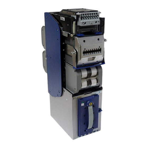
Page 11: Description Of Modules
2.2. Description of Modules Bill-to-Bill™ XT consists of following modules Memory Card Sense-a-Click Validating Head MFL Bezel Housing B2B Power Interface Module Box Control Unit Dispensing Cassette Recycling Cassette (3 pcs) Path Switch Drop Cassette Validating Head – Accepts, validates banknotes and controls rest of the device. Bezel –... -
Page 12: Validating Head - Mflv-9013
Power Interface Module – Handles communication with host controller and distribution of power to internal modules. Memory Card – Provides easy upgrade of firmware. Recycling Cassettes – Store and recycle about 100 bills Dispensing Cassette – Dispense up to 20 bills Path Switch –... -
Page 13: Sense-A-Click
The banknote path may be accessed by opening the two guides. This is done by lifting the latches as shown below. 2.4. Sense-A-Click Sense-A-Click modules contain optical, inductive and dielectric sensors for secure banknote validation. Coupons are validated by a barcode sensor. An anti-stringing sensor provides protection against cheating attempts. - Page 14 Sense-a-Click sensor pak (upper) Sense-a-Click sensor pak (lower) A special tool OPT-HW-FT01 is available for easy removal of Sense-A-Clicks. - 14 - © 2015 Suzo-Happ...
-
Page 15: Housing - Bbh-5521
2.5. Housing - BBH-5521 The Housing is made of a rigid metal structure, to facilitate easy mounting of the device. 2.6. Bezel 5 types of bezels are available as listed below. Status Light - 15 - © 2015 Suzo-Happ... -
Page 16: Chassis - Bbc-0310
Standard Bezel Running Lights Bezel MFLB-2401 MFLB-4017 Digital Display Digital Display Bezel MFLB-4027 Metal (Dispenser) Bezel Metal Bezel MFLB-6301 MFLB-6101 Note: Metal bezels require additional grounding hardware. 2.7. Chassis - BBC-0310 The chassis can hold up to 3 recycling cassettes, dispensing cassette, and path switch. It also has motors for transporting banknotes to recycling cassettes and positioning the path switch. -
Page 17: Removing Chassis
Removing Chassis 2.7.1. Unlock the chassis if it is locked to the housing. Push the release bar under the validating head. Pull out the chassis with one hand while supporting with other hand. Accessing Banknote Path 2.7.2. Press both release buttons and open the chassis. -
Page 18: Installing Chassis
Path Switch Push release button to open the Chassis Optical sensors Installing Chassis 2.7.3. Make sure the lock is in unlocked position. Install the chassis with one hand while supporting with other hand. Make sure it is securely locked in position. 2.8. -
Page 19: Removing Recycling Cassettes
Type Part Number BBR-0112 Non-Lockable Narrow Tape BBR-0113 Lockable Narrow Tape BBR-0112 and BBR-0113 are used for bank notes wider than 76 mm. BBR-0111 and BBR-0113 provide locks for added security. Removing Recycling Cassettes 2.8.2. Remove the chassis from the Bill-to-Bill housing. Slide the latch on the chassis (each cassette has its own latch) and pull out the cassette. -
Page 20: Dispensing Cassette - Bbd-0610
Open the cover Plastic handle Pull the latch Rotate the plastic knob in counter-clockwise direction. Banknotes will be dispensed one at a time. A jammed banknote may easily be removed without adversely affecting operation of the cassette. When banknotes are manually removed the count in the cassette memory will be different from the actual. -
Page 21: Removing Dispensing Cassette
Removing Dispensing Cassette 2.9.1. Remove the chassis from the housing. Slide the latch on the chassis and pull out the dispensing cassette Pull out the Dispensing Cassette Slide the latch Opening Dispensing Cassette 2.9.2. Slide the metal latch and open the top cover of the dispensing cassette. -
Page 22: Path Switch - Bbs-0110
2.10. Path Switch - BBS-0110 The path switch routes the banknotes to the appropriate destination. Banknotes are routed: from validating head to any recycling cassette or cash collection system from any recycling cassette to dispensing cassette or cash collection system ... -
Page 23: Power Interface - Bbp-5730
2.11. Power Interface - BBP-5730 The power interface module is located in the housing at the left side of the validating head. This unit handles power and communication with the host. Removing Power Interface Module 2.11.1. Disconnect power Remove the screw located on the front side ... -
Page 24: Cash Box - Flsct0102
2.12. Cash Box - FLSCT0102 The Cash Box stacks and holds validated bills in a cassette. For added security the cashbox can be locked with two ¾” tubular locks. It can also be locked to the housing with a ¾” tubular lock. A security switch in the housing is used to indicate if the cash box is in position. -
Page 25: Collecting Bills
Collecting Bills 2.12.2. Unlock cashbox and open the lid. Push stacker plate down and collect bank notes. 2.13. Accessories Part Number Description Power and communication cable OPT-PS-BB-CCNET with 24 Volt power supply OPT-HS-BB-CCNET Power and communication cable Chassis Lock Installation Kit OPT-MKTBB-LOCK1 (Cam Lock) Chassis Lock Installation Kit... -
Page 26: Memory Card
2.14. Memory Card It is important to keep the Bill-to-Bill™ XT firmware up to date to ensure support of new released banknotes. This is accomplished by using memory cards. Different options for memory cards are available. Single Download Card Typical part number: TBM-31US1123. This memory card must be left in the unit for operation. - Page 27 6 Mounting Points Side Bracket Side Bracket Bill-to-Bill 300 XE Bill-to-Bill Spacer Detailed View A Recommended Installation - 27 - © 2015 Suzo-Happ...
- Page 28 3 Mounting Points Side Bracket Bill-to-Bill 300 XE Bill-to-Bill Detailed View A Spacer Alignment Pins Installation - Left Side Mounting 3 Mounting Points Side Bracket Bill-to-Bill Bill-to-Bill 300 XE Detailed View A Spacer Alignment Pins Installation - Right Side Mounting - 28 - ©...
-
Page 29: Installation Of Bezels
3.2. Installation of Bezels Door Hinge – Bezel Installation Alignment Note: The Door’s hinge must be in the area as described above in order to allow proper alignment of the bezels. Remove the protective film from the back of the bezel and insert the bezels through the door openings making sure the pins align with the inside bezels. - Page 30 Fasten the Bezels with M4 screws as described in the figure below. Bushing BB01.80.206 (8 pcs.) Unscrew pins (4 pls.) Washer M4 (8 pcs.) Screw M4x8 (9 pcs.) Grounding Cable Mounting Points for outside Bezels Note: The pins must be removed after the installation to allow proper tolerance between the inside and outside Bezels.
-
Page 31: Grounding
Recommended door openings for installation of bezels 3.3. Grounding Protective-earth ground terminal must be connected to the automat grounding bus or terminal. Protective earth connection must be made by cable OPT-MKBB-GND or another cooper wire cable with wire gage 14…12 AWG. Use the shortest, practical wire length but - 31 - ©... - Page 32 no more than 1.5 meters. Refer to local codes and regulations for grounding requirements. The Validating Head Bezel must be properly grounded to the door, assuming that the door is internally connected to ground. Grounding Cable Validating Head Bezel Grounding - 32 - ©...
-
Page 33: Security Lock Installation (Chassis)
3.4. Security Lock Installation (Chassis) Lock Module Lock Washer M3 Screw M3 The chassis along with recycling and dispensing cassettes can be locked to the housing with a tubular lock. The lock must be installed in the lock module located on the right side of the validating head. - Page 34 M19x1 Ø7.14[9/32"-28] 28.58[1-1/8"] 5.56[7/32"] 15.88[5/8"] Cam Lock 5/8" Cam Lock 5310021 1-1/8" Nut with nylon insert (Lock's Part) 5310021 Nut with nylon insert (Lock's Part) 5104602-01 5104602 M19x1 Ø7.14[9/32"-28] M19x1 Ø7.14[9/32"-28] 28.58[1-1/8"] 5.56[7/32"] 5.56[7/32"] 15.88[5/8"] Screw M3x4 15.88[5/8"] 15.88[5/8"] Plug 3a.
-
Page 35: Security Lock Installation (Housing)
3.5. Security Lock Installation (Housing) The cash box can be locked to the housing with a ¾” tubular lock. Please follow the steps shown below. Cam, bushing and nut shown in below diagrams are included in the locking kits. Remove the screw and lock washer from the lock cover. Remove and discard the washer and spacer Install the lock and parts, as shown below Install the cover, screw and lock washer... -
Page 36: Security Lock Installation (Cash Box)
3.6. Security Lock Installation (Cash Box) Two secure locks can be installed onto the Cash Box by removing the supplied plastic lock and plug. Pay special attention to the locking directions. One lock must be locking clockwise and the other anti-clockwise. Belonging to the lock Hex Nut Washer... -
Page 37: Power & Interface Connection
4. Power & Interface Connection The power interface module provides power and communication connections through connector X2. Harness OPT-HS-BB-CCNET is supplied for this purpose. In order to prepare a custom harness, Molex plug 43645-1000 and Molex contacts 43030-0008 must be ordered. Connector pinout TERMINAL SIGNAL... -
Page 38: Modes Of Operation
5. Modes of Operation The Bill-to-Bill™ XT can be set to operate in one of two modes: Host mode or Service mode. Host mode: In this mode the device requires connectivity from a host controller or an external application. Service mode: In this mode the device operates as a standalone without external connectivity. - Page 39 Group of 4 SW 2 ON State OFF State Default SW 2.1 Four Way One Way SW 2.2 High High Security Acceptance SW 2.3 9600 19200 SW 2.4 Service Host Group of 8 SW 1 ON State OFF State Defaul SW 1.1 Bill 1 Enable Bill 1 Disable...
-
Page 40: Software Updates
The denominations assigned these switches depend on the software in use. Please refer to “Software Description for Bill to Bill Validator” document for details. 6. Software Updates Software updates can be performed using memory cards or from the host machine. 6.1. - Page 41 9. Wait until the validator has finished initialisation. 10. Observe the LED turn green. 11. Power down the validator. 12. Turn the Dip SW 4 to COMMUNICATION mode. 13. Remove the validating head. 14. Remove the memory card. 15. Install the validating head. 16.
- Page 42 6.3. Update Diagnostics During the update process the bezel LEDs will blink red-green. The LEDs will turn to steady state once the update is completed. In the event of an unsuccessful update, the LED will blink red, with short green flashes. The following table lists errors related to download process.
- Page 43 Periodic cleaning and maintenance of the unit must be performed for continued operation. Please refer to the serviceability manual for additional information. 9. Contact Information Technical Support Email: bill-to-bill@suzohapp.com Web: http://www.suzohapp.com/bill-to-bill Service Centers Please check http://www.suzohapp.com/bill-to-bill. - 43 - © 2015 Suzo-Happ...
Need help?
Do you have a question about the Bill to Bill XT and is the answer not in the manual?
Questions and answers