Table of Contents
Advertisement
Service Facts
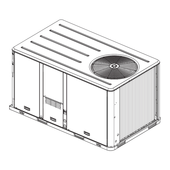
Packaged Rooftop Air Conditioners
Precedent™- Cooling and Gas/Electric
10Ton Standard Efficiency Rooftop Units
Model Numbers
Only qualified personnel should install and service the equipment. The installation, starting up, and servicing
of heating, ventilating, and air-conditioning equipment can be hazardous and requires specific knowledge and
training. Improperly installed, adjusted or altered equipment by an unqualified person could result in death or
serious injury. When working on the equipment, observe all precautions in the literature and on the tags,
stickers, and labels that are attached to the equipment.
July 2014
TSC120F
SAFETY WARNING
RT-SVF28F-EN
YSC120F
Advertisement
Table of Contents

Related Manuals for Ingersol Rand Precedent TSC120F Series


Summary of Contents for Ingersol Rand Precedent TSC120F Series
- Page 1 Service Facts Packaged Rooftop Air Conditioners Precedent™- Cooling and Gas/Electric 10Ton Standard Efficiency Rooftop Units Model Numbers TSC120F YSC120F SAFETY WARNING Only qualified personnel should install and service the equipment. The installation, starting up, and servicing of heating, ventilating, and air-conditioning equipment can be hazardous and requires specific knowledge and training.
-
Page 2: Introduction
Introduction Read this manual thoroughly before operating or servicing this unit. WARNING Warnings, Cautions, and Notices Proper Field Wiring and Grounding Required! Safety advisories appear throughout this manual as Failure to follow code could result in death or serious required.Your personal safety and the proper operation of injury. -
Page 3: Copyright
Introduction Copyright This document and the information in it are the property of Trane, and may not be used or reproduced in whole or in part without written permission.Trane reserves the right to revise this publication at any time, and to make changes to its content without obligation to notify any person of such revision or change. -
Page 4: Table Of Contents
Table of Contents Introduction Electromechanical Control Evaporator Fan ......2 Operation (for Gas Units) ... . .17 Warnings, Cautions, and Notices . -
Page 5: General Data
General Data Table 1. General data -10 tons - standard efficiency Table 1. General data -10 tons - standard efficiency 10 Tons 10 Tons T/YSC120F3,4,W T/YSC120F3,4,W Cooling Performance Heating Performance (Gas/Electric Only) Gross Cooling Capacity 119,000 11.3 Heating Input Nominal cfm/AHRI Rated cfm 4,000/3,500 Low Heat Input (Btu) 150,000/105,000... -
Page 6: Evaporator Fan Performance
Evaporator Fan Performance Table 2. Direct drive evaporator fan performance - 10 tons standard efficiency - TSC120F3,4,W downflow airflow External Static Pressure (Inches of Water) 1.00 rpm bhp rpm bhp rpm bhp rpm bhp rpm bhp rpm bhp rpm bhp rpm bhp rpm 3200 1028 0.67 1054 0.74 1079 0.81 1105 0.88 1131 0.96 1157 1.04 1184 1.12 1209 1.21 1234 1.30... - Page 7 Evaporator Fan Performance Table 4. Direct drive evaporator fan performance - 10 tons standard efficiency with gas heat - YSC120F3,4,W*L,M low & medium heat downflow airflow External Static Pressure (Inches of Water) 1.00 rpm bhp rpm bhp rpm bhp rpm bhp rpm bhp rpm bhp rpm bhp rpm bhp rpm 3200 1055 0.73 1081 0.81 1105 0.88 1128 0.94 1152 1.01 1177 1.09 1202 1.17 1225 1.25 1249 1.33...
- Page 8 Evaporator Fan Performance Table 6. Direct drive evaporator fan performance - 10 tons with standard efficiency gas heat - YSC120F3,4,W*H high heat downflow airflow External Static Pressure (Inches of Water) 1.00 rpm bhp rpm bhp rpm bhp rpm bhp rpm bhp rpm bhp rpm bhp rpm bhp rpm 3200 1055 0.70 1082 0.79 1109 0.87 1132 0.93 1156 1.01 1180 1.09 1205 1.17 1228 1.25 1252 1.33...
-
Page 9: Performance Data
Performance Data Table 9. 10 tons air temperature rise across electric Table 8. RPM table heaters (°F) T/YSC120F 10 Tons 4000 cfm Potentiometer Potentiometer Motor RPM Motor RPM Voltage Voltage Stages TSC120F3,4,W 18.0 14.2 1.25 4.50 1061 27.0 21.3 1.50 4.75 1126 36.0... -
Page 10: Electrical Data
Electrical Data Table 12. Unit wiring - standard efficiency Standard Indoor Fan Motor Max Fuse Size Unit Model Voltage or Max Circuit Tons Number Range Breaker T/YSC120F3 187-253 49.6 T/YSC120F4 414-506 22.7 T/YSC120FW 517-633 18.9 (a) The standard motor for the 3-phase models is a Belt Drive Motor. Table 13. - Page 11 Electrical Data Table 15. Electrical characteristics - standard evaporator fan motor - 60 cycle - direct or belt drive standard efficiency Unit Model Direct or Belt Amps Tons Number Drive Volts Phase T/YSC120F3 Direct Drive 208-230 3.80 8.50-8.50 — T/YSC120F4 Direct Drive 3.60 4.30...
-
Page 12: Sequence Of Operation
Sequence of Operation Three-Stages of Cooling These units are offered with two control options, electromechanical and ReliaTel™. When the unit is configured for three-stage cooling, and Note: Refer to the unit nameplate: If the 9th digit of the the system switch is set to the cool position and the zone model number = R, proceed with the following temperature rises above the cooling setpoint control band, Sequence of Operation. -
Page 13: Reliatel Control Evaporator Fan Operation (For Cooling Only Units)
Sequence of Operation ReliaTel Control Evaporator Fan Operation compressor on and off times are still active during compressor operation. (for Cooling Only Units) Dual Compressor Units When the fan selection switch is set to the “Auto” position, the RTRM energizes the (K6) relay coil approximately 1 The dehumidification cycle is only permitted above 40ºF as second after energizing the compressor contactor coil indicated above and is not permitted during a heating... -
Page 14: Reliatel Control Cooling With An Economizer
Sequence of Operation 6. A purge cycle takes priority over normal cooling or 2. Reference Enthalpy - controlling the economizer cycle dehumidification requests, but will discontinue for all by sensing the outdoor air humidity. Table 18, p. 14 high priority lockouts and alarms. lists the selectable enthalpy values by potentiometer setting. -
Page 15: Drain Pan Condensate Overflow Switch (Optional)
Sequence of Operation Drain Pan Condensate Overflow Switch starts a 20-second pre-purge (15 seconds on high speed followed by 5 seconds on low speed). If the pressure (Optional) switch (PS) is still open, the inducer blower will continue to This input incorporates the Condensate Overflow Switch be energized on high speed until pressure switch closure. -
Page 16: Supply Air Setpoint Reset
Sequence of Operation cooling," the economizer will be used first to attempt to setpoint.The amount is zero where they are equal and satisfy the supply setpoint. On units with economizer, a increases linearly toward the value set at the reset amount call for cooling will modulate the fresh air dampers open. -
Page 17: Electromechanical Control Evaporator Fan Operation (For Gas Units)
Sequence of Operation satisfy the cooling requirement, the thermostat closesY2. damper.The ECA continues to modulate the economizer The compressor contactor (CC2) coil is energized provided damper open/closed to keep the mixed air temperature in the low pressure control (LPC2), high pressure control the 50ºF to 55ºF range. -
Page 18: Drain Pan Condensate Overflow Switch (Optional)
Sequence of Operation energizes the second stage of the gas valve and the second stage of inducer blower. When the zone thermostat is satisfied, the (IGN) de- energizes the gas valve.The (IGN) senses loss of flame. The (IGN) initiates a 5 second inducer blower post purge and 90 second indoor blower delay off at current speed. -
Page 19: Pressure Curves
Pressure Curves Figure 1. T/YSC120F pressure curve system 1 115F OD Ambient 105F OD Ambient 95F OD Ambient 85F OD Ambient 75F OD Ambient 65F OD Ambient 55F OD Ambient Suction Pressure, PSIG Figure 2. T/YSC120F pressure curve system 2 115F OD Ambient 105F OD Ambient 95F OD Ambient... -
Page 20: Subcooling Charging Chart
Subcooling Charging Chart Figure 3. T/YSC120F subcooling charging chart - PSIG SYS 1 SYS 2 RT-SVF28F-EN... -
Page 21: Refrigerant Circuit
Refrigerant Circuit Figure 4. T/YSC120F RT-SVF28F-EN... - Page 24 The manufacturer optimizes the performance of homes and buildings around the world. A business of Ingersoll Rand, the leader in creating and sustaining safe, comfortable and energy efficient environments,the manufacturer offers a broad portfolio of advanced controls and HVAC systems, comprehensive building services, and parts. For more information, visit www.IRCO.com.
Need help?
Do you have a question about the Precedent TSC120F Series and is the answer not in the manual?
Questions and answers