Table of Contents
Advertisement
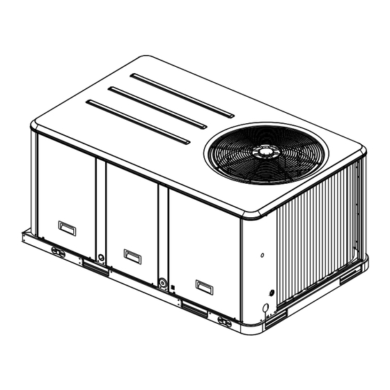
Service Facts
Packaged Rooftop Air Conditioners
Precedent™ – Cooling, Gas/Electric
6Ton Standard Efficiency Rooftop Units
Model Numbers
Only qualified personnel should install and service the equipment. The installation, starting up, and servicing
of heating, ventilating, and air-conditioning equipment can be hazardous and requires specific knowledge and
training. Improperly installed, adjusted or altered equipment by an unqualified person could result in death or
serious injury. When working on the equipment, observe all precautions in the literature and on the tags,
stickers, and labels that are attached to the equipment.
July 2014
TSC072F*
SAFETY WARNING
RT-SVF25C-EN
YSC072F*
Advertisement
Table of Contents

Related Manuals for Ingersol Rand TSC072F Series


Summary of Contents for Ingersol Rand TSC072F Series
- Page 1 Service Facts Packaged Rooftop Air Conditioners Precedent™ – Cooling, Gas/Electric 6Ton Standard Efficiency Rooftop Units Model Numbers TSC072F* YSC072F* SAFETY WARNING Only qualified personnel should install and service the equipment. The installation, starting up, and servicing of heating, ventilating, and air-conditioning equipment can be hazardous and requires specific knowledge and training.
-
Page 2: Introduction
Introduction Read this manual thoroughly before operating or servicing this unit. WARNING Warnings, Cautions, and Notices Proper Field Wiring and Grounding Required! Safety advisories appear throughout this manual as Failure to follow code could result in death or serious required.Your personal safety and the proper operation of injury. -
Page 3: Copyright
Introduction Copyright This document and the information in it are the property of Trane, and may not be used or reproduced in whole or in part without written permission.Trane reserves the right to revise this publication at any time, and to make changes to its content without obligation to notify any person of such revision or change. -
Page 4: Table Of Contents
Table of Contents Introduction Electromechanical Control Heating Operation ......2 (for Cooling Only Units) ....19 Warnings, Cautions, and Notices . -
Page 5: General Data
General Data Table 1. General data - 6 tons- standard efficiency Table 1. General data - 6 tons- standard efficiency 6 Tons 6 Tons T/YSC072F3,4,W T/YSC072F3,4,W Heating Performance Cooling Performance (Gas/Electric Only) Gross Cooling Capacity 75,000 Heating Input 11.2 Nominal cfm/ARI Rated cfm 2,400/2,100 Low Heat Input (Btu) 80,000... -
Page 6: Evaporator Fan Performance
Evaporator Fan Performance Table 2. Belt drive evaporator fan performance - 6 tons standard efficiency - TSC072F3,4,W downflow airflow External Static Pressure (Inches of Water) 0.10 0.20 0.30 0.40 0.50 0.60 0.70 0.80 0.90 1.00 rpm bhp rpm bhp rpm bhp rpm bhp rpm bhp rpm bhp rpm bhp rpm 1-hp Standard Motor &... - Page 7 Evaporator Fan Performance Table 3. Belt drive evaporator fan performance - 6 tons standard efficiency - TSC072F3,4,W horizontal airflow External Static Pressure (Inches of Water) 0.10 0.20 0.30 0.40 0.50 0.60 0.70 0.80 0.90 1.00 rpm bhp rpm bhp rpm bhp rpm bhp rpm bhp rpm bhp rpm bhp rpm bhp rpm 1-hp Standard Motor &...
- Page 8 Evaporator Fan Performance Table 4. Belt drive evaporator fan performance - 6 tons standard efficiency with gas heat - YSC072F3,4,W*L,M low & medium heat downflow airflow External Static Pressure (Inches of Water) 0.10 0.20 0.30 0.40 0.50 0.60 0.70 0.80 0.90 1.00 rpm bhp rpm bhp rpm bhp rpm bhp rpm bhp rpm bhp rpm bhp rpm...
- Page 9 Evaporator Fan Performance Table 5. Belt drive evaporator fan performance - 6 tons standard efficiency with gas heat - YSC072F3,4,W*L,M low & medium heat horizontal airflow External Static Pressure (Inches of Water) 0.10 0.20 0.30 0.40 0.50 0.60 0.70 0.80 0.90 1.00 rpm bhp rpm bhp rpm bhp rpm bhp rpm bhp rpm bhp rpm bhp rpm bhp rpm...
- Page 10 Evaporator Fan Performance Table 6. Belt drive evaporator fan performance - 6 tons standard efficiency with gas heat - YSC072F3,4,W*H high heat downflow airflow External Static Pressure (Inches of Water) 0.10 0.20 0.30 0.40 0.50 0.60 0.70 0.80 0.90 1.00 rpm bhp rpm bhp rpm bhp rpm bhp rpm bhp rpm bhp rpm bhp rpm bhp rpm 1-hp Standard Motor &...
- Page 11 Evaporator Fan Performance Table 7. Belt drive evaporator fan performance - 6 tons standard efficiency with gas heat - YSC072F3,4,W*H high heat horizontal airflow External Static Pressure (Inches of Water) 0.10 0.20 0.30 0.40 0.50 0.60 0.70 0.80 0.90 1.00 rpm bhp rpm bhp rpm bhp rpm bhp rpm bhp rpm bhp rpm bhp rpm bhp 1-hp Standard Motor &...
-
Page 12: Performance Data
Performance Data Table 8. Standard motor & sheave/fan speed (rpm) Unit Model 6 Turns 5 Turns 4 Turns 3 Turns 2 Turns 1 Turn Tons Number Sheave Open Open Open Open Open Open Closed T/YSC072F AK64x1” 1002 Note: Factory set at 3 turns open. Table 9. -
Page 13: Electrical Data
Electrical Data Table 13. Unit wiring - standard efficiency Standard Indoor Fan Motor Oversized Indoor Fan Motor Max Fuse Size Max Fuse Size Unit Model Voltage or Max Circuit or Max Circuit Tons Number Range Breaker Breaker T/YSC072F3 187-253 36.5 37.8 T/YSC072F4 414-506... - Page 14 Electrical Data Table 16. Electrical characteristics - standard evaporator fan motor - 60 cycle - belt drive standard efficiency Unit Model Amps Tons Number Volts Phase T/YSC072F3 208-230 1.00 32.2 T/YSC072F4 1.00 16.1 T/YSC072FW 1.00 13.2 Table 17. Electrical characteristics - oversized evaporator fan motor - 60 cycle - belt drive - standard efficiency Unit Model Amps Tons...
-
Page 15: Sequence Of Operation
Sequence of Operation These units are offered with two control options, maintain the zone temperature to within ± 2ºF of the sensor electromechanical and ReliaTel™. setpoint at the sensed location. Note: Refer to the unit nameplate: If the 9th digit of the Three-Stages of Cooling model number = R, proceed with the following Sequence of Operation. -
Page 16: Reliatel Control Evaporator Fan Operation (For Cooling Only Units)
Sequence of Operation system is connected to a remote panel, the “SERVICE” the reheat valve is de-energized and the compressor LED will be turned on when this failure occurs. continues to run, or the heat is turned on.The 3 minute compressor on and off times are still active during ReliaTel Control Evaporator Fan Operation compressor operation. -
Page 17: Reliatel Control Cooling With An Economizer
Sequence of Operation 6. A purge cycle takes priority over normal cooling or 2. Reference Enthalpy - controlling the economizer cycle dehumidification requests, but will discontinue for all by sensing the outdoor air humidity. Table 20, p. 17 high priority lockouts and alarms. lists the selectable enthalpy values by potentiometer setting. -
Page 18: Drain Pan Condensate Overflow Switch (Optional)
Sequence of Operation Drain Pan Condensate Overflow Switch starts a 20-second pre-purge (15 seconds on high speed followed by 5 seconds on low speed). If the pressure (Optional) switch (PS) is still open, the inducer blower will continue to This input incorporates the Condensate Overflow Switch be energized on high speed until pressure switch closure. -
Page 19: Electromechanical Evaporator Fan Operation (For Cooling Only Units)
Sequence of Operation When the thermostat fan selection switch is set to the “On” “Off” as required to maintain the zone temperature position, the (IGN) keeps the indoor fan relay coil (F) setpoint. energized for continuous fan motor operation. Electromechanical Control Heating Electromechanical Evaporator Fan Operation (for Gas Units) Operation (for Cooling Only Units) -
Page 20: Drain Pan Condensate Overflow Switch (Optional)
Sequence of Operation Table 22. Ignition module diagnostics Module is powered up, but no active call for Steady light heat. Blinking at continuous steady Active call for heat. rate One blink Loss of communication. System lockout (failure to ignite, no spark, Two blinks low/no gas pressure, etc.) Pressure switch (no vent air flow, bad CBM,... -
Page 21: Pressure Curve
Pressure Curve To Check Operating Pressures 5. Plot the outdoor dry bulb and the indoor DB/WB temperature onto the chart. 1. Start the unit and allow the pressures to stabilize. 6. At the point of intersection, read down for the suction 2. -
Page 22: Subcooling Charging Chart
Subcooling Charging Chart Figure 2. T/YSC072F subcooling charging chart RT-SVF25C-EN... -
Page 23: Refrigerant Circuit
Refrigerant Circuit Figure 3. Refrigerant circuit diagram ID COIL Filter Drier Compressor Service Valve Low Pressure Control Service Valve High Pressure Service Valve DLTS Control Refrigerant Flow Cooling System 1 RT-SVF25C-EN... - Page 24 The manufacturer optimizes the performance of homes and buildings around the world. A business of Ingersoll Rand, the leader in creating and sustaining safe, comfortable and energy efficient environments,the manufacturer offers a broad portfolio of advanced controls and HVAC systems, comprehensive building services, and parts. For more information, visit www.IRCO.com.
Need help?
Do you have a question about the TSC072F Series and is the answer not in the manual?
Questions and answers