Table of Contents
Advertisement
Advertisement
Chapters
Table of Contents

Related Manuals for Atlas 12AWFSL


Summary of Contents for Atlas 12AWFSL
- Page 1 Replace This With Cover PDF...
- Page 2 Read this entire manual before operation begins. Record below the following information which is located on the serial number data plate. Serial No. Model No. Date of Installation...
-
Page 3: Table Of Contents
Contents General Information..5 Product Identifi cation ..8 Packing, Transport, Storage ..10 Product Description ..12 Technical Specifi... - Page 4 Indicates the direction of access for motor vehicles to the lift BOLD Important information TYPE WARNING: before operating the lift and carrying out any adjustments, read chapter 7 “installation” where all proper operations for a better functioning lift are shown. 12AWFSL...
-
Page 5: General Information
PEOPLE, VEHICLES OR OBJECTS IF SAID OPERATIONS ARE CARRIED OUT BY UNAUTHORIZED PERSONNEL OR THE LIFT IS IMPROPERLY USED. Any use of the machine made by operators who are not familiar with the instructions and procedures contained herein shall be forbidden. 12AWFSL General Information... - Page 6 Operators must not be under the infl uence of sedatives, drugs or alcohol when operating the machine. Before operating the lift, operators must be familiar with the position and function of all controls, as well as with the machine features shown in the chapter “Operation and use”. General Information 12AWFSL...
- Page 7 The manufacturer is not liable for any mistakes made when drawing up this manual and reserves the right to make any changes due the development of the product, at any time. General Information 12AWFSL...
-
Page 8: Product Identifi Cation
The warranty will come immediately to an end when unauthorized modifi cations to the machine or parts of it are carried out. The presence of defects in workmanship must be verifi ed by the Manufacturer’s personnel in charge. Product Identification 12AWFSL... - Page 9 Dealer where the machine has been bought or the Manufacturer’s Commercial Department. Only skilled personnel who are familiar with the lift and this manual shall be allowed to carry out packing, lifting, handling, transport and unpacking operations. Product Identification 12AWFSL...
-
Page 10: Packing, Transport, Storage
In Figure 1 there are the correct indications for the lifting of the runways: Hoist and handle only one package at a time. Packing, Transport, Storage 12AWFSL... - Page 11 Packages must be opened paying attention not to cause damage to people (keep a safe distance when opening straps) and parts of the lift (be careful the objects do not drop from the package when opening). Packing, Transport, Storage 12AWFSL...
-
Page 12: Product Description
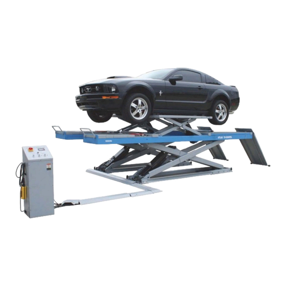
All mechanical frames, such as platforms, extensions, base frames and arms have been built in steel plate to make the frame stiff and strong while keeping a low weight. The electro hydraulic operation is described in detail in chapter 8. Figure 2 – Lift Product Description 12AWFSL... - Page 13 If so, the fi nal lowering button can be pressed and the lift be lowered. A beep sound is heard during the last travel. Product Description 12AWFSL...
-
Page 14: Technical Specifi Cation
Noise level 80 dB(A)/1m Working temperature -10 °C ÷ 40 °C Package weight 5900 lbs including all Electric Motor Type ML90L2 Voltage 220V-1Ph Power 2.2 KW N° Poles Speed 2800 rpm Motor enclosure type Insulation class IP 54 Technical Specification 12AWFSL... - Page 15 If there is over 10% fl uctuation on the electrical power supply, it is suggested to use the voltage stabilizer to protect the electrical components and system from overloading. Pump Type Gear Flow rate 1.3 cm Continuous working pressure 260 bar Peak pressure 280 bar Technical Specification 12AWFSL...
- Page 16 Figure 3A – Layout For In-Ground Installation Technical Specification 12AWFSL...
- Page 17 Figure 3B – Layout For On-Ground Installation Technical Specification 12AWFSL...
- Page 18 Hydraulic Unit The hydraulic power unit is equipped with Figure 4 – Hydraulic Power Unit Technical Specification 12AWFSL...
- Page 19 ASTM D 2270 Viscosity index 104 N° ASTM D 97 Pour point ~ 30 °C ASTM D 92 Flash point 215 °C ASTM D 644 Neutralization number 0.5 mg KOH/g CHANGE HYDRAULIC OIL AT 1 YEAR INTERVALS Technical Specification 12AWFSL...
- Page 20 Parachute valves (optional) Lowering control valve Leveling cutoff cock 1 - runways Motor Leveling cutoff cock 2 – jacks Gear pump Switching solenoid valve - runways Oil fi lter Switching solenoid valve – jacks Emergency hand pump Technical Specification 12AWFSL...
- Page 21 Figure 6 – Electrical Plan (220V- 1Ph) Technical Specification 12AWFSL...
- Page 22 Top limit switch Safety height limit switch Lowering solenoid valve (220v) Switching solenoid valve - runways (220v) Switching solenoid valve - wheel free jacks (220v) Safety air valve - runways (220v) Safety air valve - wheel free jacks (220v) Technical Specification 12AWFSL...
- Page 23 Fig. 7 – Pneumatic Plan Filter/regulator is to be supplied by the customer if not order specially. Technical Specification 12AWFSL...
-
Page 24: Safety
Never use the lift when safety devices are off-line. People, the lift and the vehicles lifted can be seriously damaged if these instructions are not followed. Figure 8 - Safety Area (Min. 3 Feet) Safety 12AWFSL... - Page 25 The operator must be sure no one is in danger before operating the lift. Bumping Risk When the lift is stopped at relatively low height for working, the risk of bumping against projecting parts occurs. Safety 12AWFSL...
- Page 26 Operate the lift only for the use it has been designed for and follow the maintenance schedule shown in the chapter “Maintenance”. Safety 12AWFSL...
- Page 27 • A special design of the hydraulic system, in case of pipeline failure, to prevent sudden lift lowering. The maximum pressure valve has been preset by the manufacturer to a proper pressure. DO NOT try to adjust it to overrun the rated lifting capacity. Safety 12AWFSL...
-
Page 28: Installation
If an installation is made in a hole, the real side of the hole must be verifi ed (as per drawing sent at the order). For installation on raised surface, the compliance with the maximum carrying capacity of the surface is recommended. Installation 12AWFSL... - Page 29 • Place the control unit in the position provided for (the control unit can be place in either right side or left side). Figure 15 – Foundation Pit Plan (Only For Flush Mounted, With The Jack Beam) Installation 12AWFSL...
- Page 30 fi ttings clean from dust. Failure to do so may result in hydraulic line failure which may result in damage or personal harm. Figure 16 – Hydraulic Connections Installation 12AWFSL...
- Page 31 When routing the pneumatic line, make sure that the tube is clear of any moving part. Failure to do so may result in safety failure which may result in damage or personal harm. Figure 17 – Pneumatic System Connection Installation 12AWFSL...
- Page 32 • Grease sliding all pivot pins; • Pour oil in the tank (3.5 to 5 Gallons of AW32 - AW46 Hydraulic Oil); • Verify that the control unit is powered by turning on the power switch; Installation 12AWFSL...
- Page 33 • Press the lowering button to lower the runway P2 completely; • Repeat raise and lower the runway P2 completely at least 5 times; • Raise the runway P2 to the same height as the runway P1; • Turn off the leveling cutoff cock 1; Installation 12AWFSL...
- Page 34 • Turn off the leveling cutoff cock 2; • Set ADJ/WORK selector into the position “WORK” after bleeding; • Lower and raise both jacks at least 3 times to check the level. If not leveled, repeat above procedure. Installation 12AWFSL...
- Page 35 • After drilling, remove dust thoroughly from each hole using compressed air or wire brush. • Assemble the washers and nuts on the anchors then tap into each hole with a hammer until the washer rests against the bases. 12AWFSL Installation...
- Page 36 • If the switch was not functioning properly, it’s possible to adjust it by screwing the nuts of switch; • Tighten the nuts after adjustment. • Fix the switch cover with the supplied screws. Installation 12AWFSL...
- Page 37 The rear beam must be attached to the runways when 2 rolling jacks are needed for lifting a vehicle. Otherwise, the manufacturer will not be responsible for any damage of the lift. Installation 12AWFSL...
- Page 38 Carry out two or three complete cycles of lowering and lifting and check: • Repeat the 7.12 section • Check no strange noise during lifting and lowering • If the platforms or jacks weren’t leveled, repeat the 7.8 section Installation 12AWFSL...
-
Page 39: Operation And Use
If an anchor bolt becomes loose or any component of the lift is found to be defective, DO NOT USE THE LIFT until repairs are made. Do not permit the electric control unit to get wet! Controls Figure 25 – Control Panel Operation And Use 12AWFSL... - Page 40 MAIN/JACK SELECTOR (4) The selector can be set in two positions: • Position : the runway electric circuit is powered for operation • Position : the electric circuit for wheel free jack is powered for operation Operation And Use 12AWFSL...
- Page 41 Always ensure that the safeties are engaged before any attempt is made to work on or near the vehicle. Make sure to engage the mechanical safety locks when the vehicle is left on the runways for long periods (ex. during the night). Operation And Use 12AWFSL...
- Page 42 • Press the lifting button to lift the vehicle to the required height; • To rest the jacks in standing position at the desired height by releasing the lifting button; • Push the safety engaging button to engage the mechanical safeties. Operation And Use 12AWFSL...
- Page 43 In case of an emergency the runways or wheel free jacks can be lowered manually to its initial position as follows referring to the Figure 26 and the Figure 27: • Padlock the power switch; • Open the front cover of the control unit; Operation And Use 12AWFSL...
- Page 44 In this case, do not need to press the emergency button continuously. Tightening or loosening the screw can reduce or increase the lowering speed. Operation And Use 12AWFSL...
- Page 45 • Re-tighten the emergency screw (2) by turning it clockwise after the jacks are lowered. Operation Of Jack Beam (Optional) The jack beam is to be operated by an air-hydraulic pedal pump supplied with the lift. Figure 28 - Jack Beam Controls Operation And Use 12AWFSL...
- Page 46 • Check to be sure the oil in the pump tank is suffi cient; • Adjust extensions according to vehicle; • Adjust the lifting adaptor height properly. If necessary, place the appropriate extensions on the lifting adaptors. Operation And Use 12AWFSL...
- Page 47 • Raise the jack beam a little bit by depressing the lifting pedal; • Release the mechanical safety by turning up the safety lever; • Depressing the lowering pedal on the pump until the jack beam is lowered completely. Operation And Use 12AWFSL...
-
Page 48: Maintenance
Ordinary Maintenance The lift has to be properly cleaned at least once a month using self-cleaning clothes. Lubricate all pivot pins at least once a week. The use of water or infl ammable liquid is strictly forbidden. Maintenance 12AWFSL... - Page 49 Every 12 Electrical limit switch and control panel operate properly must be months system carried out by skilled electricians empty the oil tank and change the hydraulic oil Maintenance 12AWFSL...
-
Page 50: Troubleshooting
The lowering solenoid valve Check and clean, if dirty, or pressed does not close replace, if faulty The emergency screw of Re-tighten the screw lowering valve does not close The suction pump fi lter is Check and clean if needed dirty Troubleshooting 12AWFSL... - Page 51 The lift does Clean, if necessary replace or not stop at the The electric board is faulty verify if powered and check safety height magneto for damage The electric board is not Replace electric board operating Troubleshooting 12AWFSL...
- Page 52 Bleed the hydraulic system into hydraulic circuit The lift does not lift or lower The pump fi lter is dirty. Check and clean if needed. smoothly Check the seal and replace if The pump suction is blown needed Troubleshooting 12AWFSL...
-
Page 53: Parts List
Lift Parts List Item Part Num Description 825DL1-100000 Runway P1 825DL1-200000 Runway P2 0206036 Screw M6X8 - GB/T818 8240D03000 Control unit 0206013 Screw M4X12 - GB/T818 0206017 Screw M4X25 - GB/T818 0505018 Safety position limit switch 8108 Parts List 12AWFSL... - Page 54 Screw M16X40- GB/T5783 0208011 Washer D.16- GB/T93 0205020 Washer D.16- GB/T97.1 J07Q Jacking beam HJ-75B J62B400000 Long ramp for on-ground installation (Optional) 8240TX-000863 Hose corner cover for on-ground installation (Optional) 8240B-008640 Hose cover for on-ground installation (Optional) Parts List 12AWFSL...
- Page 55 Part Num Description 824-110000G Base 824-100003 Lower shaft 0209025 Screw M8X12 - GB/T79 0210018 Self-lubricated bush 3055 8250-02-01-17 Cylinder lower shaft 8250-120-00 Master hydraulic cylinder 8250-06-03 Lower safety rack 0511228 Screw M8X10 0306010 Air locking cylinder 32X23 Parts List 12AWFSL...
- Page 56 Jack lower safety rack 8250-00D P1 jack hydraulic cylinder CXQ-61X5.5 Hose holder 824-100001G Nylon slider 824-130000G Outer scissor arm 824-100004 Middle shaft 8250-02-26 Spacer 0209012 Screw M8X12 - GB/T78 0210080 Self-lubricated bush 4055 8250-18 Shim ZJJ3-17 Shim Parts List 12AWFSL...
- Page 57 PI jack cylinder liner ZJJ40-02D Piston ZJJ40-04D Cylinder shaft ZJJ40-05D Cylinder guiding cover 8250-06C Shaft support ZJJ40-07D Air bleeding plug 0312016 Gasket 80X60X22.4 0309041 O-ring 80X3.1 0309030 O-ring 50X3.1 0305006 Guide ring 45X25X2.5 0311009 Scraper 45X53X5 0215059 Steel ball D.6 Parts List 12AWFSL...
- Page 58 Front base ZJJ3-0103 U connection rod 824-112000 Rear base 824-110001 Wheel guide 0204032 Nut M16 - GB/T6172.1 0207022 Screw M10X20 - GB/T819.1 0201180 Screw M16X85 - GB/T5780 0201103 Screw M16X50 - GB/T5781 0203025 Nut M16 - GB/T6170 Parts List 12AWFSL...
- Page 59 Turntable recess base plate 0207036 Screw M8X20 - GB/T70.3 8240B4-03150A Spacer 8240B4-031501 Movable spacer 8240C4-031501 Movable spacer 0202032 Screw M6X16 - GB/T70.1 825D-145000 Slipping plate assembly 825D-000001 Spacer 825D-140100 Spacer 0205013 Washer D.12 - GB/T97.1 0201074 Screw M12X30 - GB/T5781 Parts List 12AWFSL...
- Page 60 Item Part Num Description 824-140006 Upper wheel guide 0209028 Screw M10X16 - GB/T79 0205008 Washer D.8 - GB/T97.1 0206037 Screw M8X25 - GB/T70.2 0202040 Screw M8X16 - GB/T70.1 824-140007 Guide fastening plate Parts List 12AWFSL...
- Page 61 Description 825D-145100 Base plate J63A332000 Roller gasket 0206032 Screw M6X16 - GB/T818 825D-142001 Slipping plate 824B-142200 Stop pin 0207036 Screw M8X20 - GB/T70.3 0203004 Nut M6 - GB52 XSZ-6-1 Spring 824EH000382 Spring cradle 824B-142003 Bolt - GB/T905 Parts List 12AWFSL...
- Page 62 Part Num Description 824-05-00 Jack table 824-05-9 Table extension 0202024 Screw M6X12 - GB/T70.1 8250-04-02-08 Upper shaft 0210013 Self-lubricated bush 3024 0209025 Screw M8X12 - GB/T79 824-152000 Outer scissor arm 0204060 Self-locking nut M25X1.5 824-04-01-08 Middle shaft Parts List 12AWFSL...
-
Page 63: Upper Wheel Guide
Description 824-153000 Inner scissor arm 8250-04-02-02 Lower wheel 0210016 Self-lubricated bush 3040 GJ300-400009 Shim 2 0210017 Self-lubricated bush 3050 ZJJ3-04-01-09A Spacer 0209002 Screw M6X10 - GB/T79 0210057 Self-lubricated bush 3035 8250-04-01-02 Upper wheel 8250-04-01-01 Upper wheel shaft Parts List 12AWFSL... - Page 64 Part Num Description 824-110000G Base 824-100003 Lower shaft 0209025 Screw M8X12 - GB/T79 0210018 Self-lubricated bush 3055 8250-02-01-17 Cylinder lower shaft 8250-100-00 Slave hydraulic cylinder 8250-06-04 Lower safety rack 0511228 Screw M8X10 0306010 Air locking cylinder 32X23 Parts List 12AWFSL...
-
Page 65: Washer D.8 - Gb/T97.1
Jack lower safety rack 8250-00C P2 jack hydraulic cylinder CXQ-61X5.5 Hose holder 824-100001G Nylon slider 824-130000G Outer scissor arm 824-100004 Middle shaft 8250-02-26 Spacer 0209012 Screw M8X12 - GB/T78 0210080 Self-lubricated bush 4055 8250-18 Shim ZJJ3-17 Shim Parts List 12AWFSL... - Page 66 Guide ring 50X25X2.5 0311010 Scraper50X58X5 0306087 Silencer 1/8 8250-95-30 P2 jack cylinder liner ZJJ40-02B Piston ZJJ40-04C Cylinder shaft ZJJ40-05C Cylinder guiding cover 8250-06C Shaft support 0312019 Gasket 95X75X22.4 0309045 O-ring 95X3.1 0309031 O-ring 55X3.1 0310015 Seal 50X60X6 Parts List 12AWFSL...
- Page 67 Screw M8X20 - GB/T70.3 8240B4-03150A Spacer 8240B4-031501 Movable spacer 8240C4-031501 Movable spacer 825D-245000 Slipping plate assembly 825D-000001 Spacer 825D-140100 Spacer 0202032 Screw M6X16 - GB/T70.1 0205013 Washer D.12 - GB/T97.1 0201074 Screw M12X30 - GB/T5781 824-140006 Upper wheel guide Parts List 12AWFSL...
-
Page 68: Screw M8X25 - Gb/T70.2
Item Part Num Description 0209028 Screw M10X16 - GB/T79 0205008 Washer D.8 - GB/T97.1 0206037 Screw M8X25 - GB/T70.2 0202040 Screw M8X16 - GB/T70.1 824-140007 Guide fastening plate Parts List 12AWFSL... - Page 69 Description 825D-145100 Base plate J63A332000 Roller gasket 0206032 Screw M6X16 - GB/T818 825D-242001 Slipping plate 0207036 Screw M8X20 - GB/T70.3 824B-142200 Stop pin 0203004 Nut M6 - GB52 XSZ-6-1 Spring 824EH000382 Spring cradle 824B-142003 Bolt - GB/T905 Parts List 12AWFSL...
- Page 70 Top cover 0206059 Screw M4X8 0508330 Guide DZ47 L=80mm 0508330 Guide DZ47 L=45mm 0507349 CPU board 101.2 0504016 Fuse 1A(5X20) 0204077 Screw M3X12 0206058 Screw M5X10 0510380 Ground decal 0206019 Screw M4X6 - GB/T818 0508017 Cable relief GM-2314 Parts List 12AWFSL...
- Page 71 0306177 Solenoid air valve G1/4 3V210-08(220V) 0205001 Washer D.3 - GB/T97.1 0208001 Washer D.3 - GB/T93 0203001 Nut M3 - GB52 J04A031000 Lower box J04A030003 Front cover 0206028 Screw M5X25 - GT/T818 0207019 Screw M8X20 - GB/T819.1 Parts List 12AWFSL...
- Page 72 Item Part Num Description 3032084008 Rubber pad 3002005001 Support BZ-W4K1Y Hydraulic power unit Parts List 12AWFSL...
- Page 73 Hydraulic Power Unit Parts List Item Part Num Description BZ-ZB-W4 Manifold BZ-W-YK1 Interface block BZ-DJ-1B Motor fl ange BZ-ZT24 Motor joint BZ-BJ25 Pump joint BZ-G18X110 Oil suction pipe BZ-G14X200 Oil return pipe BZ-SD-01 Manifold plug HK2-0200 Oil tank Parts List 12AWFSL...
- Page 74 Locking washer D.6 - GB/T93 0203004 Nut M6 - GB/T6170 0209042 Screw M6X8 - GB/T80 0202036 Screw M6X65 - GB/T70.1 0208006 Locking washer D.8 - GB/T93 0202045 Screw M8X20 - GB/T70.1 0313001 Washer BS/A13.7 BZ-HC2-0 Starting valve for 1Ph (Optional) Parts List 12AWFSL...
- Page 75 Lifting arm 0212004 Seeger D.25 HJ-RG-10-4 Shaft J07K210000 Beam 0206031 Screw M6X10 - GB/T818 0215021 Greaser 8X1 HJ-63-0 Jack hydraulic cylinder unit 0211003 Seeger D.19 0210009 Bush SF-1/2525 HJ-RG-19 Cylinder upper shaft 0202045 Screw 8X20 - GB/T70.1 Parts List 12AWFSL...
- Page 76 Central shaft 0301052 Air-hydraulic pedal pump 800CC 0206001 Screw M8X12 - GB/T818 0205008 Washer D.8 - GB/T97.1 6740A-61101A Pump tray 0202040 Screw M8X16 - GB/T70.1 J07K120000 Base extension J07Q110000 Jack base HJ-63-1 Jack cylinder liner 0212005 Seeger D.20 Parts List 12AWFSL...
- Page 77 Outer threaded bush 0212034 Seeger D.42 Z23A313001 Inner threaded bush 0212035 Seeger D.32 Z23A313100 Pad support Z23A313202 Rubber pad 0202032 Screw M6X16 - GB/T70.1 Z23A601200 Adaptor extension H80 (For special request) Z23A601300 Adaptor extension H155 (For special request) Parts List 12AWFSL...
- Page 78 Jack master hydraulic cylinder 8250-00D Jack slave hydraulic cylinder ZW5430 Hydraulic hose 1/4 L=5430 ZZ3600 Hydraulic hose 1/4 L=3600 ZW3700 Hydraulic hose 1/4 L=3700 ZZ1800 Hydraulic hose 1/4 L=1800 ZZ1400 Hydraulic hose 1/4 L=1400 ZZ5350 Hydraulic hose 1/4 L=5350 Parts List 12AWFSL...
- Page 79 Air-hydraulic pedal pump 800CC ZJ380 PU hydraulic hose L=380 ZJ700 Hydraulic hose L=700 BZ-720B-0401 Bolt BZ-GZ-002 Screw 0303065 Union (1B-04) 0303027 Bolt (720B-04) 0313001 Washer (BS/A13.70) 0305001 Plug (ZBJ22 007-QD07) 0306112 Quick union (Φ8 G1-4) 0303064 Union 3/8 (1BT-04-06SP) Parts List 12AWFSL...
- Page 80 Air safety release cylinder 32X23 0306086 Silencer 1/4 0306002 Y quick union 8 0306158 Y quick union 6 0306025 Tee quick union 6 0306041 Quick union 6 0306032 90 degree quick union 8-1/4 0306047 90 degree quick union 6-1/4 Parts List 12AWFSL...
- Page 81 0306101 Spiral rilsan hose 6X4 L=4000 (Optional) 0306082 Rotation 90 degree union 6-1/4 (Optional) 0306192 Switching valve VMS-114 (Optional) 8250N61-810002G Special nut (Optional) 8250N61-810001G Union (Optional) 0306044 Quick union 8-1/4 (Optional) 0306097 Rilsan hose 8X5 L=12000 (Optional) Parts List 12AWFSL...
-
Page 82: Warranty
Prices do not include any local, state or federal taxes. RETURNS: Products may not be returned without prior written approval from the Manufacturer. DUE TO THE COMPETITIVENESS OF THE SELLING PRICE OF THESE LIFTS, THIS WARRANTY POLICY WILL BE STRICTLY ADMINISTERED AND ADHERED TO. Warranty 12AWFSL...
Need help?
Do you have a question about the 12AWFSL and is the answer not in the manual?
Questions and answers