Advertisement
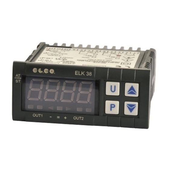
ELK 38
MICROPROCESSOR-BASED
DIGITAL
ELECTRONIC CONTROLLER
OPERATING INSTRUCTIONS
Vr. 02 (ENG) - cod.: ISTR 06261
EL.CO. S.r.l.
VIA MARCONI, 49
36030 PIEVEBELVICINO (VI) ITALY
TEL.: +39 0445 661722
FAX: +39 0445 661792
internet : http:\\www.elco-italy.com
e-mail: info@elco-italy.com
FOREWORD:
This manual contains the information necessary for the product to
be installed correctly and also instructions for its maintenance and
use; we therefore recommend that the utmost attention is paid to the
following instructions.
Though this manual has been issued with the greatest care, ELCO
S.r.l. will not take any responsibility deriving from its use.
The same applies to each person or Company involved in the
issuing of this manual.
This document is the exclusive property of ELCO S.r.l.
forbids any reproduction and divulgation , even in part, of the
document, unless expressly authorized.
ELCO S.r.l. reserves the right to make any formal or functional
changes at any moment and without any notice.
ELCO S.r.l. - ELK 38 - OPERATING INSTRUCTIONS - Vr. 02 - ISTR 06261 - PAG. 1
INDEX
1
INSTRUMENT DESCRIPTION
1.1
GENERAL DESCRIPTION
1.2
FRONT PANEL DESCRIPTION
2
PROGRAMMING
2.1
FAST PROGRAMMING OF SET POINT
2.2
SELECTION OF CONTROL STATE AND PARAMETER
PROGRAMMING
2.3
PARAMETER PROGRAMMING LEVELS
2.4
CONTROL STATES
2.5
ACTIVE SET POINT SELECTION
3
INFORMATION ON INSTALLATION AND USE
3.1
PERMITTED USE
3.2
MECHANICAL MOUNTING
3.3
ELECTRICAL CONNECTIONS
3.4
ELECTRICAL WIRING DIAGRAM
4
FUNCTIONS
4.1
MEASURING AND VISUALIZATION
4.2
OUTPUTS CONFIGURATION
4.3
ON/OFF CONTROL
4.4
NEUTRAL ZONE ON/OFF CONTROL
4.5
SINGLE ACTION PID CONTROL
4.6
DOUBLE ACTION PID CONTROL
4.7
AUTO-TUNING AND SELF-TUNING FUNCTIONS
4.8
REACHING OF SET POINT AT CONTROLLED SPEED
AND AUTOMATIC COMMUTATION BETWEEN TWO
SET POINTS
4.9
SOFT-START FUNCTION
4.10
ALARM FUNCTIONS
4.10.1 ALARM OUTPUT CONFIGURATION
4.10.2 ALARM HYSTERESIS
4.11
LOOP BREAK ALARM FUNCTION
4.12
FUNCTION OF KEY "U"
4.13
PARAMETERS CONFIGURATION BY KEY01
5
PROGRAMMABLE PARAMETERS
5.1
PARAMETERS TABLE
5.2
PARAMETERS DESCRIPTION
6
PROBLEMS , MAINTENANCE AND GUARANTEE
6.1
ERROR SIGNALLING
6.2
CLEANING
6.3
GUARANTEE AND REPAIRS
7
TECHNICAL DATA
7.1
ELECTRICAL DATA
7.2
MECHANICAL DATA
7.3
MECHANICAL DIMENSIONS, PANEL CUT-OUT AND
MOUNTING
7.4
FUNCTIONAL DATA
7.5
MEASUREMENT RANGE TABLE
7.6
INSTRUMENT ORDERING CODE
1 - INSTRUMENT DESCRIPTION
1.1 - GENERAL DESCRIPTION
ELK 38 is a "single loop" digital microprocessor-based controller,
with ON/OFF, Neutral Zone ON/OFF, PID single action, PID dual
action (direct and reverse) control and with AUTO-TUNING FAST
function, SELF-TUNING function and automatic calculation of the
FUZZY OVERSHOOT CONTROL parameter for PID control.
The PID control has a particular algorithm with TWO DEGREES OF
which
FREEDOM that optimises the instrument's features independently in
the event of process disturbance and Set Point variations.
The process value is visualized on 4 red displays, while the output
status is indicated by 2 LED displays.
The instrument is equipped with a 3 LED programmable shift
indexes .
The instrument provides for the storage of 4 Set Points and can
have up to 2 outputs: relay type or can drive solid state relays type
(SSR).
Depending on the model required the input accept:
C: Thermocouples temperature probes (J,K,S and ELCO IRS
Infrared
sensors),
Thermoresistances PT100.
mV
signals
(0..50/60
mV,
12..60
mV),
Advertisement
Table of Contents

Related Manuals for elco ELK 38


Summary of Contents for elco ELK 38
- Page 1 Depending on the model required the input accept: C: Thermocouples temperature probes (J,K,S and ELCO IRS Infrared sensors), signals (0..50/60 12..60 mV), Thermoresistances PT100. ELCO S.r.l. - ELK 38 - OPERATING INSTRUCTIONS - Vr. 02 - ISTR 06261 - PAG. 1...
-
Page 2: Front Panel Description
Set Point, or alternatively, if no key is visualise the code of the group of parameters. pressed for approx. 15 seconds, the display will return to normal functioning automatically. ELCO S.r.l. - ELK 38 - OPERATING INSTRUCTIONS - Vr. 02 - ISTR 06261 - PAG. 2... - Page 3 AUTOMATIC CONTROL (rEG) – Automatic control is the normal functioning state of the controller. ELCO S.r.l. - ELK 38 - OPERATING INSTRUCTIONS - Vr. 02 - ISTR 06261 - PAG. 3...
-
Page 4: Electrical Connection
10 sec., then it will be deactivated for 10 Thermistors PTC and NTC. sec. and so on until the measurement error remains.). ELCO S.r.l. - ELK 38 - OPERATING INSTRUCTIONS - Vr. 02 - ISTR 06261 - PAG. 4... -
Page 5: Outputs Configuration
[SP + HSEt]. active Set Point “SP”, on the functioning mode "Func” and on the instrument’s PID algorithm with two degree of freedom. ELCO S.r.l. - ELK 38 - OPERATING INSTRUCTIONS - Vr. 02 - ISTR 06261 - PAG. 5... - Page 6 The AUTO-TUNING and SELF-TUNING functions permit the out auto-tuning at every instrument switch on ("Auto" = 1). automatic tuning of the PID controller. ELCO S.r.l. - ELK 38 - OPERATING INSTRUCTIONS - Vr. 02 - ISTR 06261 - PAG. 6...
-
Page 7: Soft-Start Function
“HAL1” - ALARM HYSTERESIS Examples with starts from values lower than SP and with decreasing “AL1d” – ALARM ACTIVATION DELAY (in sec.) of SP. ELCO S.r.l. - ELK 38 - OPERATING INSTRUCTIONS - Vr. 02 - ISTR 06261 - PAG. 7... - Page 8 ("AL1H"). conditions and then back in alarm conditions. ELCO S.r.l. - ELK 38 - OPERATING INSTRUCTIONS - Vr. 02 - ISTR 06261 - PAG. 8...
-
Page 9: Programmable Parameters
Set point SPAt Active Set point 1 ÷ nSP SP1 Set Point 1 SPLL ÷ SPHL SP2 Set Point 2 SPLL ÷ SPHL ELCO S.r.l. - ELK 38 - OPERATING INSTRUCTIONS - Vr. 02 - ISTR 06261 - PAG. 9... - Page 10 SP” (PARAMETERS RELATIVE TO THE SET POINT): 27 HAL1 Alarm AL1 hysteresis OFF ÷ 9999 These allow the setting of the control Sets and the Sets function modes. ELCO S.r.l. - ELK 38 - OPERATING INSTRUCTIONS - Vr. 02 - ISTR 06261 - PAG. 10...
- Page 11 AL1 – ALARM AL1 THRESHOLD : Alarm AL1 threshold for low and instrument to give the power programmed on par. “OPE” as output. high alarms. The possibilities are : ELCO S.r.l. - ELK 38 - OPERATING INSTRUCTIONS - Vr. 02 - ISTR 06261 - PAG. 11...
- Page 12 INTERFACE) : This contains the parameters relative to the key [SP- |SP/2|] or higher (with “Func” =CooL) than [SP+ |SP/2|]. U and display functions. = OFF - Autotuning disabled. ELCO S.r.l. - ELK 38 - OPERATING INSTRUCTIONS - Vr. 02 - ISTR 06261 - PAG. 12...
- Page 13 7.3 – MECHANICAL DIMENSIONS, PANEL CUT-OUT AND programmed on par “OPE” and activates the desired alarms, if the MOUNTING [mm] relative parameters “ALni” have been programmed = yES. ELCO S.r.l. - ELK 38 - OPERATING INSTRUCTIONS - Vr. 02 - ISTR 06261 - PAG. 13...
- Page 14 -200 ... 850 ° C -199.9 ... 850.0 ° C “SEnS” = Pt1 -328 ... 1562 ° F -199.9 ... 999.9 ° F ELCO S.r.l. - ELK 38 - OPERATING INSTRUCTIONS - Vr. 02 - ISTR 06261 - PAG. 14...
Need help?
Do you have a question about the ELK 38 and is the answer not in the manual?
Questions and answers