
Related Manuals for Nidec Control Techniques Digitax-SF Series


Summary of Contents for Nidec Control Techniques Digitax-SF Series
- Page 1 Instruction Manual AC SERVO MOTOR and SERVO DRIVE Series Digitax-SF Part Number: 0478-0606-01 Issue: 1...
- Page 2 Digitax SF Thank you for your purchase of the products. This Instruction Manual includes precautions for the product use. ■ Please study this manual first and use the product properly and safely. ■ Before using the product, be sure to carefully read the Safety Instructions. ■...
-
Page 3: Table Of Contents
Digitax SF Overview of the Instruction Manual 1. Before Use Safety Precautions, Safety Standards, Maintenance and Inspection 2. Specifications Model Codes, Component Identifications, Specifications, and Dimensions 3. Preparation Installation, System Wiring, and Timing Diagrams 4. Connections CN1 User I/O Connector Pinout Options and Control Modes 5. -
Page 4: Table Of Contents
Contents Before Use 1. Important Safety Instructions ..........2 2. - Page 5 6. Operation 1. Configuring Operatin g Mode..........2 2.
- Page 6 MEMO Digitax SF Instruction Manual...
- Page 7 Before Use 1. Important Safety Instructions ......2 1.Safety Precautions � � � � � � � � � � � � � � � � � � � � � � � � � � � � � � � � � � � � � � � � �2 2.Other Considerations and Precautions �...
- Page 8 1. Before Use 1. Important Safety Instructions 1. Important Safety Instructions 1.Safety Precautions This manual uses the signs below to indicate serious but avoidable problems caused by misuse of the product� One is for death or serious bodily harm� The other is for bodily injury or product or equipment damage�...
- Page 9 1. Before Use 1. Important Safety Instructions Drives and controllers are intended as components for professional incorporation into complete systems. If installed incorrectly they may present a safety hazard. The drive uses high voltages and currents, carries a high level of stored electrical energy, and is used to control equipment which can cause injury.
- Page 10 1. Before Use 1. Important Safety Instructions Stored Electrical Charge The drive contains capacitors that remain charged to a potentially lethal voltage after the AC supply has been disconnected. If the drive has been energized, the AC supply must be isolated at least ten minutes before work may continue.
- Page 11 1. Before Use 1. Important Safety Instructions Adjusting parameters Some parameters have a profound effect on the operation of the drive. They must not be altered without careful consideration of the impact on the controlled system. Measures must be taken to prevent unwanted changes due to error or tampering. Electromagnetic compatibility (EMC) Installation instructions for a range of EMC environments are provided in an EMC datasheet.
- Page 12 1. Before Use 1. Important Safety Instructions DANGER Sign Precautionary Measures If Not Observed Installation and Wiring the AC mains Never connect the motor directly to power supply� drive Do not place any flammable items near the motor or � Protect the drive with a protective enclosure and ensure the clearance between the drive, the enclosure and other devices is as specified in this manual...
- Page 13 1. Before Use 1. Important Safety Instructions DANGER Sign Precautionary Measures If Not Observed Additional Precautions Install external emergency stop circuitry so that the operation can be stopped and the power supply can be shut down immediately in case of emergency�...
- Page 14 1. Before Use 1. Important Safety Instructions CAUTION Sign Precautionary Measures If Not Observed Installation and Wiring parts of any connectors Do not directly touch the terminal Do not block the air vents� Do not allow ingress of any foreign objects to the product�...
- Page 15 1. Before Use 1. Important Safety Instructions CAUTION Sign Precautionary Measures If Not Observed Transportation and Storage Do not store the product at a location subject to water or moisture, or where toxic gases or liquids are present� Do not hold the cables or motor shafts during transportation� drive motor When transporting the...
- Page 16 1. Before Use 1. Important Safety Instructions 2.Other Considerations and Precautions Export of this product or its applications If the end user or application is involved in military activities or weapons, its export may be export restrictions� subject to Ensure trade compliance and are completed adequate...
- Page 17 1. Before Use 1. Important Safety Instructions 3.Safety Standards Not Applicable Drive Rating Motor EN60034-1 (*1) Low Voltage Directive EN61800-5-1 EN60034-5 EN61000-6-2 (*2) EU/EC Directives EMC Directive EN55011 Class A, Group1 Machinery Directive (N/A) (N/A) 1004-1 508C UL Standards (*1) 1004-6 (File No�E471456)...
-
Page 18: Issue
EU Declaration of Conformity This declaration is issued under the sole responsibility of the manufacturer 1. Name and address of the manufacturer Nidec Control Techniques Ltd The Gro Newtown Powys SY16 3BE Registered in England and Wales. Company Reg. No. 01236886 Telephone: 00 44 1686 612300 E mail: marketing.control techniques@mail.nidec.com... -
Page 19: Before Use
1. Before Use 1. Important Safety Instructions 4.Maintenance and Inspection attempt to repair Never the product� For safe use of the product, be sure to perform regular maintenance and drive inspection of the and motor� Ensure the electrical and mechanical safety before each inspection� This product assumes the following operating conditions�... - Page 20 1. Before Use 2. Overview 2. Overview Misuse or mishandling of the product will not only result in its sub optimal performance, but also failure or shorter service life� For safety and proper use of the product, please read the instruction manuals carefully� About This Product and This Instruction Manual ■...
-
Page 21: Specifications
1. Before Use 2. Overview 1.Product Label Motor Label The product label is separated in two parts which are located shown in this picture� Label 1 AC SERVO MOTOR Motor Model MX401N2SN01 3φAC150V 2.7A INPUT RATED OUTPUT W 3000 RATED REV. rpm Specifications Label 2 Specifications RATED FREQ. Hz 1.27... - Page 22 1. Before Use 2. Overview 2.Danger Signs NO IMPACT/NO DISASSEMBLY LABEL attempt Do not remove the encoder cover� Never to repair or replace the encoder� Any shock applied to the encoder cover cause encoder failure� Do not apply strong impact to the motor shaft HOT SURFACE WARNING Do not touch the product during operation or for...
- Page 23 1. Before Use 2. Overview MEMO Digitax SF nstruction Manual...
- Page 24 Specifications Motor. 1...........2 1.
- Page 25 2. Specifications 1. Motor 1. Motor 1. Models ** Control Number Encoder Code Specifications 17 bit (Incremental) 17 bit (Absolute) Shaft end specifications/Oil Seal Code Rated Output Oil Seal S (P) Straight Without K (H) Without T (R) Straight With L (J) With Voltage...
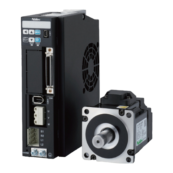
- Page 26 2. Specifications 1. Motor 2. Names of parts Motor: Encoder Connector Brake Connector Motor Power Connector Oilseal Radial direction Flange Shaft Oilseal Thrust direction Encoder Cover Frame Mounting hole Motor: (MM102 & MH102) Oilseal Brake Connector Motor Power Connector Encoder Connector Radial direction Flange Shaft...
- Page 27 2. Specifications 1. Motor 3. Specifications Item Specifications 0 to 40 ℃ Ambient temperature for operation 20 to 85 %RH (no condensation) Ambient humidity for operation - 20 to 65 ℃ (no condensation) Ambient temperature for storag (not subjected to direct sunlight) 80 ℃ for 72 hours 20 to 85 %RH ...
- Page 28 2. Specifications 1. Motor 50 W Motor Model : MY500 □ 2 □ □ ** Item Unit Specifications Item Unit Specifications Rotor inertia – Middle Usage – Holding Fitting flange size 40 sq. Rated voltage DC 24 V ± 10 % Without brake Rated current 0.25...
- Page 29 2. Specifications 1. Motor 100 W Motor Model : MY101 □ 2 □ □ ** Item Unit Specifications Item Unit Specifications Rotor inertia – Middle Usage – Holding Fitting flange size 40 sq. Rated voltage DC 24 V ± 10 % Without brake Rated current 0.25...
- Page 30 2. Specifications 1. Motor 200 W Motor Model : MX201 □ 2 □ □ ** Item Unit Specifications Item Unit Specifications Rotor inertia – Usage – Holding Fitting flange size 60 sq. Rated voltage DC 24V ± 10 % Without brake Rated current Approximate mass With brake...
- Page 31 2. Specifications 1. Motor Motor Model : MZ201 □ 2 □ □ ** Item Unit Specifications Item Unit Specifications Rotor inertia – High Usage – Holding Fitting flange size 60 sq. Rated voltage DC 24 V ± 10 % Without brake Rated current Approximate mass With brake...
- Page 32 2. Specifications 1. Motor 400 W Motor Model : MX401 □ 2 □ □ ** Item Unit Specifications Item Unit Specifications Rotor inertia – Usage – Holding Fitting flange size 60 sq. Rated voltage DC 24 V ± 10 % Without brake Rated current Approximate mass...
- Page 33 2. Specifications 1. Motor Motor Model : MZ401 □ 2 □ □ ** Item Unit Specifications Item Unit Specifications Rotor inertia – High Usage – Holding Fitting flange size 60 sq. Rated voltage DC 24 V ± 10 % Without brake Rated current Approximate mass With brake...
- Page 34 2. Specifications 1. Motor 750 W Motor Model : MX751 □ 2 □ □ ** Item Unit Specifications Item Unit Specifications Rotor inertia – Usage – Holding Fitting flange size 80 sq. Rated voltage DC 24 V ± 10 % Without brake Rated current Approximate mass...
- Page 35 2. Specifications 1. Motor Motor Model : MZ751 □ 2 □ □ ** Item Unit Specifications Item Unit Specifications Rotor inertia – High Usage – Holding Fitting flange size 80 sq. Rated voltage DC 24 V ± 10 % Without brake Rated current Approximate mass With brake...
- Page 36 2. Specifications 1. Motor Motor Model : MM102 □ 2 □ □ ** Item Unit Specifications Item Unit Specifications Rotor inertia – Middle Usage – Holding Fitting flange size 130 sq. Rated voltage DC 24 V ± 10 % Without brake Rated current Approximate mass With brake...
- Page 37 2. Specifications 1. Motor Motor Model : MH102 □ 2 □ □ ** Item Unit Specifications Item Unit Specifications Rotor inertia – High Usage – Holding Fitting flange size 130 sq. Rated voltage DC 24 V ± 10 % Without brake Rated current Approximate mass With brake...
- Page 38 2. Specifications 1. Motor 1.5 kW Motor Model : MM152 □ 2 □ □ ** Item Unit Specifications Item Unit Specifications Rotor inertia – Middle Usage – Holding Fitting flange size 130 sq. Rated voltage DC 24 V ± 10 % Without brake Rated current Approximate mass...
- Page 39 2. Specifications 1. Motor Motor Model : MH152 □ 2 □ □ ** Item Unit Specifications Item Unit Specifications Rotor inertia – High Usage – Holding Fitting flange size 130 sq. Rated voltage DC 24 V ± 10 % Without brake Rated current Approximate mass With brake...
- Page 40 2. Specifications 1. Motor 2 kW Motor Model : MM202 □ 2 □ □ ** Item Unit Specifications Item Unit Specifications Rotor inertia – Middle Usage – Holding Fitting flange size 130 sq. Rated voltage DC 24 V ± 10 % Without brake Rated current Approximate mass...
- Page 41 2. Specifications 2. Encoder 2. Encoder 1. Specifications Item Specifications Motor model M□□□□□2□N** M□□□□□2□A** Resolution Incremental 17 bit Absolute 17 bit Ambient operating temperature 0 to 85 ℃ Environmental requirements External disturbance magnetic field ±2 mT ( 20 G ) or below Voltage DC 4.5 to 5.5 V (Power supply ripple ≤...
- Page 42 2. Specifications Drive 1. Model Specifications Series Code Specifications Standard Standard Main Circuit Power Supply Code Supply 50 W 100 W 200 W 400 W 750 W 1 kW 1.5 kW 2 kW Compatible Motor Code Model Rated Output M □ 500 □ 2 □ □ * * 50 W M □...
- Page 43 2. Specifications Drive 2. Names of parts Drive Mounting holes CN3 PC communication connector ⌀ 5.5 (one location) Used for parameter settings, tuning, and status display in the dedicated The recommended screw: M5x12 mm, with spring washer Digitax SF Connect software“...
- Page 44 2. Specifications Drive Drive Mounting holes CN3 PC communication connector ⌀ 5.5 (two locations) The recommended screw: M5x12 mm and 8 mm, with spring washer Used for parameter settings, tuning, and status display in the dedicated Setting panel Digitax SF Connect software“...
- Page 45 2. Specifications Drive 3. Specifications Basic Specifications Item Specifications Model DA2YZ _ _ DA2Z1 _ _ DA212 _ _ DA224 _ _ DA238 _ _ DA24A _ _ DA26B _ _ DA28C _ _ Compatible Motor M□500 M□101 M□201 M□401 M□751 M□102 M□152...
- Page 46 2. Specifications Drive Environmental Specification Item Specifications For operation (*5) 0 to 5 ℃ Ambient temperature For storage -20 to 65 ℃ For operation Ambient 20 to 85 % RH (no condensation ) humidity For storage Atmosphere for operation and Indoors (not subject to direct sunlight )...
- Page 47 2. Specifications Drive Functions Specifications Position Control Mode Item Specifications inhibit position error Servo ON, alarm reset, command input , emergency stop, counter clear, 2- Control input inhibit (limit switch input) stage torque limit, CCW/CW run , ABS data demand, homing start Alarm status, servo status, servo ready, under torque limit, brake release, emergency stop positioning complete, motion complete, alarm,...
- Page 48 2. Specifications Drive Torque Control Mode Item Specifications inhibit Servo ON, alarm reset, command input (zero clamp command) 2- Control input inhibit (limit switch inputs) stage torque limit, CCW/CW run Control output Alarm status, servo status, servo ready, under torque limit, brake release Torque command input Input voltage, -...
-
Page 49: Preparation
2. Specifications Drive Notice Drive AC Supply as the I n the DA24A □□ (1 kW), single-phase can be used source. To use single- *1) power connectors. phase 200 to 240 VAC, connect it to the primary circuit L1 and L3 Item Specifications Drive... - Page 50 2. Specifications Drive Overload Detection Feature Digitax SF drives provide overload protection - overload alarm output and emergency stop upon alarm output -in case of motor operation with load level above the overload detection curve shown below. 1000 1000 Detection Time [s] Detection Time [s] 1000 1000...
- Page 51 2. Specifications Drive 4. Dimensions Figure 1 φ5.5 16 10 φ5.5 2-M5 Mounting Dimension Figure 2 φ5.5 16 10 φ5.5 2-M5 Mounting Dimension (mm) Digitax SF nstruction Manual...
- Page 52 2. Specifications Drive Figure 3 φ5.5 φ5.5 2-M5 Mounting Dimension (mm) Figure 4 φ5.5 φ5.5 61.7 61.7 φ5.5 3-M5 Mounting Dimension (mm) Digitax SF nstruction Manual...
- Page 53 Preparation 1. Installation ........2 1.
- Page 54 3. Preparation 1. Installation 1. Installation Installation and Operating Environment Ensure that the environment for installation and operation meet the requirements specified in this document. Should you use the product in conditions different from the specifications, please contact us. - Do not install the product where it could be directly exposed to direct sunlight. drive - Be sure to install each inside a control panel.
- Page 55 3. Preparation 1. Installation 1. Motor Installation Do not use any other screws but those in the recommended sizes. Motor Mounting Screws Mounting Motor Model Hole Recommended Size Diameter MM500, MY500 M4 × 12 mm or more 2- ⌀ 4.5 MM101, MY101 Hexagon socket head bolt MA201, MH201, MX201, MZ201...
-
Page 56: Connections
3. Preparation 1. Installation Connection with Machines Use a coupling to absorb angle and direction deviations so that the motor shaft load will be less than the rated allowable axial load. Otherwise, the bearing life in the motor will be shorter, or the shaft may become damaged. If you are using a rigid coupling, install it very carefully such that the axial misalignment will be minimal. -
Page 57: Operation 7
3. Preparation 1. Installation Drive Installation AC Supply Do not turn on the or the control power until all wiring work is completed. Mounting Orientation and Clearance drives maintain When installing required clearances for protective enclosures and control panels for heat dissipation and air flow. - Page 58 3. Preparation 1. Installation Drives Mounting drive Be sure to mount each conductive surface such as aluminum brushed plate. drive Hook the U-shaped installation notch of the to the bolt that has been screwed in advance. drive Tighten the mounting screws on the top.
- Page 59 3. Preparation 2. System Wiring 2. System Wiring DANGER Be mindful when wiring and handling high voltage materials Earth / Ground connection is a must. Ensure the incoming supply to the power supply providing the control AC Supply 24V supply is from the same source as the AC supply AC Supply Do not use the...
- Page 60 3. Preparation 2. System Wiring 1. System Wiring Wiring pattern 1 AC Supply ■Explanatory notes High Voltage Non-dangerous voltage cable Circuit breaker Ground resistance : 100 Ω max. Surge absorber Control power DC24 V Digitax SF Connect EMC noise filter Host control equipment Control power DC24 V AC supply contactor Braking resistor Control signal I/O cable Encoder cable Motor power cable Motor power cable Emergency To connect to the ...
- Page 61 3. Preparation 2. System Wiring Wiring Pattern 2 ■Explanatory notes AC Supply High Voltage Non-dangerous voltage cable Circuit breaker Ground resistance : 100 Ω max. Surge absorber Control power DC24 V Digitax SF Connect EMC noise filter Host control equipment Control power DC24 V AC supply contactor Braking resistor Control signal I/O cable Encoder cable Motor power cable Motor power cable Emergency stop To connect to the braking unit Encoder connector Motor power...
- Page 62 3. Preparation 2. System Wiring Wiring Pattern 3 ■Explanatory notes AC Supply High Voltage Non-dangerous voltage cable Circuit breaker Ground resistance : 100 Ω max. Surge absorber Control power DC24 V Digitax SF Connect EMC noise filter Host control equipment Control power DC24 V AC supply contactor Braking resistor Control signal I/O cable Encoder cable Motor power cable Motor power cable Emergency stop To connect to the braking unit Encoder connector Motor power...
- Page 63 3. Preparation 2. System Wiring Wiring Pattern 4 (MM102 & MH102) ■Explanatory notes AC Supply High Voltage Non-dangerous voltage cable Circuit breaker Ground resistance : 100 Ω max. Surge absorber Control power DC24 V Digitax SF Connect EMC noise filter Host control equipment Control power DC24 V AC supply contactor Braking resistor Control signal I/O cable Encoder cable Motor power cable Brake connector 1 kW only Motor power cable Motor power connector...
- Page 64 3. Preparation 2. System Wiring 2. Connecting Equipment and Recommended Peripherals AC Suppl Please use this product in the power supply environment of Over-Voltage Category Ⅱ defined by AC Supply drives IEC60664-1. This is the Drives 50 W to 750 W :Single-phase AC200 V -10 % to AC240 V +10 % Drives 1 kW to 2 kW ...
- Page 65 3. Preparation 2. System Wiring EMC noise filter EMC filters prevent emission of electromagnetic interference onto the AC supply lines .To ensure compliance with EMC, use the recommended noise filter. Recommended Singlephase: 4200-0056 OKAYA Electric Industries Co Ltd Product Threephase: 4200-3106 Digitax SF drive 's EMC testing.
- Page 66 3. Preparation 2. System Wiring Emergency stop brake emergency stop This product is not equipped with a brake emergency stop Use the following circuit example when building a brake circuit. Select a cement resistor of 6.8 Ω 10 W. Select coil surge protection relays with diode. For wiring with the motor power line, UL wires (AWG18 / 600 V or equivalent) are recommended.
- Page 67 3. Preparation 2. System Wiring 3.Wiring to the Connectors Motor Connector Pinout Motor Encoder Connector ・Incremental ・Incremental Housing 172168-1 Housing 172160-1 Contact 170363-1 Contact 170365-1 (Tyko Electronics JAPAN) (Tyko Electronics JAPAN) ・Absolute ・Absolute Housing 172169-1 Housing 172161-1 Contact 170363-1 Contact 170365-1 (Tyko Electronics JAPAN) (Tyko Electronics JAPAN) Wires:AWG22 (Power), AWG24 (Signal)
- Page 68 3. Preparation 2. System Wiring Motor (MM102 & MH102) Encoder Connector ・Incremental / Absolute Straight Plug CM10-SP10S- □ -D ・Incremental / Absolute Right Angle Plug CM10-AP10S- □ -D CM10-R10P-D (D7) □: S, M or L (DDK) (DDK) Wires:AWG22 (Power), AWG24 (Signal) Brake Connector Straight Plug CM10-SP2S- □...
- Page 69 3. Preparation 2. System Wiring Drive Connectors and Pinouts Drive Cable Connector PC Communication Connector UC60SC-MB-5ST USB mini B (Hirose Electric) User I/O Connector Plug 10150-3000-PE(3M) Cover 10350 ( 3M) DF02R050NA1(JAE) or Equivalent alternatives Wires:AWG26 Encoder Connector 3E106-2230KV(3M) Connector 3E206-0100KV (3M) Cover 3E306-3200-008(3M) Wires:AWG22 (Power), AWG24 (Signal) Motor Power Connector Accessories 2092-1325 (WAGO JAPAN) 2092-1525/002-000(WAGO JAPAN) Wires:AWG18 (UL) Accessories AC Supply Power Connector 2092-1102/002-000(WAGO JAPAN) 2092-1422 (WAGO JAPAN) Wires:AWG18 (UL) Name Code...
- Page 70 3. Preparation 2. System Wiring Drive Cable Connector PC Communication Connector UC60SC-MB-5ST USB mini B (Hirose Electric) User I/O Connector Plug 10150-3000-PE(3M) Cover 10350 ( 3M) DF02R050NA1(JAE) or Equivalent alternatives Wires:AWG26 Encoder Connector 3E106-2230KV(3M) Connector 3E206-0100KV (3M) Cover 3E306-3200-008(3M) Wires:AWG22 (Power), AWG24 (Signal) Motor Power Connector Accessories 2092-3323 (WAGO JAPAN) 2092-3523/002-000(WAGO JAPAN) Wires:AWG18 (UL) AC Supply Accessories Power Connector 2092-1104/002-000(WAGO JAPAN) 2092-1424 (WAGO JAPAN) Wires:AWG18 (UL) Name Code Pin No. Signal Description Braking...
- Page 71 3. Preparation 2. System Wiring Drive Cable Connector PC Communication Connector UC60SC-MB-5ST USB mini B (Hirose Electric) User I/O Connector Plug 10150-3000-PE(3M) Cover 10350 ( 3M) DF02R050NA1(JAE) or Equivalent alternatives Wires:AWG26 Encoder Connector 3E106-2230KV(3M) Connector 3E206-0100KV (3M) Cover 3E306-3200-008(3M) Wires:AWG22 (Power), AWG24 (Signal) Motor Power Connector Accessories 2092-3323 (WAGO JAPAN) 2092-3523/002-000(WAGO JAPAN) Wires:AWG18 (UL) Accessories AC Supply Power Connector 2092-3105/002-000(WAGO JAPAN) 2092-3425 (WAGO JAPAN) Wires:AWG14 (UL) Name Code Pin No. Signal Description Braking...
- Page 72 3. Preparation 2. System Wiring 4. Accessory Connector Connector Parts Gripping plate with a sliding connector release Pushbutton Orange-colored part: Connector release (orange part) Locking latch Stripping cables with recommended tools Model Code Image Use this tool to connect or disconnect a cable to a connector. 210-720 (standard type made in Europe) Pushbutton Tools...
- Page 73 3. Preparation 2. System Wiring Connecting the connectors AC Supply power connector Hold the grip plate and keep pushing in until you hear a clicking sound. Motor power connector Hold the frame of the connector and keep pushing in until you hear a clicking sound. Disconnecting the connectors AC Supply power...
- Page 74 3. Preparation 2. System Wiring Wire connection With the orange pushbutton pushed in with the tool, insert the wire until it hits the round insertion slot. (the image to the left). Release the pushbutton to finish. (the image in the middle) Pull the wire slightly to verify that the wire connection is not loose.
- Page 75 3. Preparation 2. System Wiring 5. Cables Recommended cable wires Use our recommendations below to select cables based on your actual usage. (Equivalent alternatives are also good) Temperature Voltage Cable Name Note Rating Rating Motor power 2517 105 ℃ 300 V (≤...
- Page 76 3. Preparation 3. Timing Diagrams 3. Timing Diagrams List of Timing Diagrams When designing a host controller system, consider the timing of control signal input from the controller to the drive drive , or alarm signal output from the Description Refer to Turning the Power On Servo OFF →...
- Page 77 3. Preparation 3. Timing Diagrams Turning the Power On Signal Description Timing Diagrams Name (Output Transistor Status, I/O Input Status, and Internal Status) Control Power DC24V ≧ 0 sec AC Supply Power L1L2 or L1L2L3 Internal Power Ready PRDY 1 sec(typ.) Servo Ready SRDY (*2) 1 sec(typ.) ...
- Page 78 3. Preparation 3. Timing Diagrams Servo OFF → ON Signal Description Timing Diagrams Name (Output Transistor Status, I/O Input Status, and Internal Status) AC Supply Power L1L2 or L1L2L3 Servo Ready SRDY Servo On SVON Internal Internal Error Status NO ERROR 150 ms(typ.) ...
- Page 79 3. Preparation 3. Timing Diagrams Servo ON → OFF (Motor idling) Signal Description Timing Diagrams Name (Output Transistor Status, I/O Input Status, and Internal Status) AC Supply Power L1L2 or L1L2L3 Servo Ready SRDY Internal Servo On SVON Internal Internal Error Status NO ERROR Internal Motor Excitation Status -...
- Page 80 3. Preparation 3. Timing Diagrams Servo ON → OFF (Motor rotating) Signal Description Timing Diagrams Name (Output Transistor Status, I/O Input Status, and Internal Status) AC Supply Power L1L2 or L1L2L3 Servo Ready SRDY Servo On SVON Internal Internal Error Status NO ERROR 20 ms(typ.) ...
- Page 81 3. Preparation 3. Timing Diagrams Alarm Occurs Signal Description Timing Diagrams Name (Output Transistor Status, I/O Input Status, and Internal Status) AC Supply Power L1L2 or L1L2L3 Servo Ready SRDY 2 ms(typ.) Servo On SVON Internal ERROR Internal Error Status 2 ms(typ.) Internal Motor Excitation Status - 2 ms(typ.) ...
- Page 82 3. Preparation 3. Timing Diagrams Alarm Reset (Servo ON) Signal Description Timing Diagrams Name (Output Transistor Status, I/O Input Status, and Internal Status) AC Supply Power L1L2 or L1L2L3 Servo Ready 2 ms(typ.) SRDY Servo On SVON 25 ms(min.) Reset RESET 20 ms(typ.) Internal Internal Error Status ERROR...
- Page 83 3. Preparation 3. Timing Diagrams Alarm Reset (Servo OFF) Signal Description Timing Diagrams Name (Output Transistor Status, I/O Input Status, and Internal Status) AC Supply Power L1L2 or L1L2L3 Servo Ready 2 ms(typ.) SRDY Servo On SVON 25 ms(min.) Reset RESET 20 ms(typ.) Internal ERROR Internal Error Status...
- Page 84 3. Preparation 3. Timing Diagrams Motor Brake Release Deceleration Stop: Timing for Engaging Brake (No.232.3) = 0 Signal Description Timing Diagrams Name (Output Transistor Status, I/O Input Status, and Internal Status) Servo On SVON 20 ms(typ.) Internal Motor Excitation Status ON ...
- Page 85 3. Preparation 3. Timing Diagrams Emergency stop Brake Release emergency Upon Servo ON, if Deceleration stop (when Servo is OFF) : Method (No.224.0) = 3 ( stop brake) Signal Description Timing Diagrams Name (Output Transistor Status, I/O Input Status, and Internal Status) AC Supply Power L1L2 or L1L2L3...
- Page 86 3. Preparation 3. Timing Diagrams Deceleration Stop Status where [Deceleration Stop Method (at Servo OFF) (No.224.0)] and [Deceleration Stop coast to stop Method (at Alarm ON)] are set to Coast to Stop Deceleration Stop Status During coast to stop Deceleration stop: Deceleration stop status during (No.232.1) = 0 (OFF) Signal Description Timing Diagrams...
- Page 87 3. Preparation 3. Timing Diagrams When Servo becomes OFF while motor is in motion and then the motor decelerates to stop by the quick stop method. Delay time for Quick Stop Complete Deceleration stop: Method (at Servo OFF) (No.224) = 2 (quick stop) Signal Description Timing Diagrams Name...
- Page 88 Connections 1. Introduction ........2 2.
- Page 89 4. Connection 1. Overview 1. Introduction Digitax SF features seven operation modes for motor, which are combinations of Control Mode and Command Follow the appropriate Mode options. CN1 connector wiring according to the mode that you are using. Control Mode Command Mode Command Input Signal Format dif.
- Page 90 4. Connection Introduction Pinout Diagram The pinout depends on the control mode / motion mode that you are using. Pins are grouped to five categories. Group Description The pinout depends on the control mode / motion mode that you are using. These are i General-Purpose Input nput terminals, such as control power, I/O power, and Servo ON.
- Page 91 4. Connection 2. Position Control Mode 2. Position Control Mode 1. Pulse Train Command Differential, Standard I/O Setting dif. Pinout Diagram Command Input Encoder Output RS-485 Communication Signal Signal Signal Description Description Description CMD_PLS OUT_A /485 Pulse, QEP A-phase or CCW A-phase /Data /CMD_PLS...
- Page 92 4. Connection 2. Position Control Mode CN1 Connector Wiring Example dif. Pulse Train Command, Differential, Standard I/O Configuration Control Power Drive Servo 24 V 24 V Twisted Pair Cable Control power supply 24 V input 1: 24 V Control power supply GND 2 m or 2: G24 V shorter...
- Page 93 4. Connection 2. Position Control Mode Differential, I/O Setting Option 1 dif. Pinout Diagram Command Input Encoder Output RS-485 Communication Signal Signal Signal Description Description Description CMD_PLS OUT_A /485 Pulse, QEP A-phase or CCW A-phase /Data /CMD_PLS /OUT_A /Pulse, QEP /A-phase or /CCW /A-phase Data CMD_DIR...
- Page 94 4. Connection 2. Position Control Mode CN1 Connector Wiring Example dif. Pulse Train Command, Differential, I/O Configuration Option 1 Control Power Drive Servo 24 V 24 V Twisted Pair Cable Control power supply 24 V input 1: 24 V Control power supply GND 2: G24 V 2 m or shorter...
- Page 95 4. Connection 2. Position Control Mode Differential, I/O Setting Option 2 dif. Pinout Diagram Command Input Encoder Output RS-485 Communication Signal Signal Signal Description Description Description OUT_A CMD_PLS /485 Pulse, QEP A-phase or CCW A-phase /Data /CMD_PLS /OUT_A /Pulse, QEP /A-phase or /CCW /A-phase Data OUT_B...
- Page 96 4. Connection 2. Position Control Mode CN1 Connector Wiring Example dif. Pulse Train Command, Differential, I/O configuration Option 2 Control Power Drive Servo 24 V 24 V Twisted Pair Cable Control power supply 24 V input 1: 24 V Control power supply GND 2: G24 V 2 m or shorter...
- Page 97 4. Connection 2. Position Control Mode 24V open collector, Standard I/O configuration Pinout Diagram Command Input Encoder Output RS-485 Communication Signal Signal Signal Description Description Description /CMD_PLS OUT_A /485 /Pulse, QEP /A-phase or /CCW A-phase /Data CC-P /OUT_A Open collector power 24V-PLS /A-phase Data CC-D...
- Page 98 4. Connection 2. Position Control Mode CN1 Connector Wiring Example Pulse Train Command, 24V Open Collector, Standard I/O Configuration Control Power Drive Servo Twisted Pair Cable 24 V 24 V Control power supply 24 V input 1: 24 V Pulse Train 2 m or Command Input shorter...
- Page 99 4. Connection 2. Position Control Mode 5V open collector, Standard I/O configuration Pinout Diagram Command Input Encoder Output RS-485 Communication Signal Signal Signal Description Description Description CC-P_5V_ OUT_A /485 Open collector power 5V-PLS A-phase /Data /CMD_PLS /OUT_A /Pulse, QEP /A-phase or /CCW /A-phase Data CC-D_5V...
- Page 100 4. Connection 2. Position Control Mode CN1 Connector Wiring Example Pulse Train Command, 5V Open Collector, Standard I/O Configuration Control Power Drive Servo Twisted Pair Cable Control power supply 24 V input 1: 24V 2m or shorter Control power supply GND 2: G24V Pulse Train Shielded...
- Page 101 4. Connection 2. Position Control Mode 2. Internal Position Command Standard I/O Configuration Pinout Diagram Encoder Output RS-485 Communication Signal Signal Description Description OUT_A /485 A-phase /Data /OUT_A /A-phase Data OUT_B B-phase Signal ground /OUT_B /B-phase OUT_Z Z-phase /OUT_Z /Z-phase Signal ground ―...
- Page 102 4. Connection 2. Position Control Mode CN1 Connector Wiring Example Internal Position Command, Standard I/O Configuration Control Power Drive Servo 24 V 24 V Control power supply 24 V input 1: 24 V Control power supply GND 2: G24 V I/O power supply 24 V input G24 V 3: COM+...
- Page 103 4. Connection 2. Position Control Mode Optional I/O Configuration Pinout Diagram Encoder Output RS-485 Communication Signal Signal Description Description OUT_A /485 A-phase /Data /OUT_A /A-phase Data OUT_B B-phase Signal ground /OUT_B /B-phase OUT_Z Z-phase /OUT_Z /Z-phase Signal ground ― ― ―...
- Page 104 4. Connection 2. Position Control Mode CN1 Connector Wiring Example Internal Position Command, Optional I/O Configuration Control Power Drive Servo 24 V 24 V Control power supply 24 V input 1: 24 V Control power supply GND 2: G24 V I/O power supply 24 V input G24 V 3: COM+...
- Page 105 4. Connection 3. Velocity Control Mode 3. Velocity Control Mode 1. Analog Velocity Command Pinout Diagram Command Input Encoder Output RS-485 Communication Signal Signal Signal Description Description Description A_SPEED OUT_A /485 Analog Command A-phase /Data A_GND /OUT_A Analog Command Ground /A-phase Data OUT_B...
- Page 106 4. Connection 3. Velocity Control Mode CN1 Connector Wiring Example Analog Velocity Command Control Power Drive Servo 24 V 24 V Control power supply 24 V input 1: 24 V Control power supply GND 2: G24 V I/O power supply 24 V input G24 V Twisted Pair Cable 3: COM+...
- Page 107 4. Connection 3. Velocity Control Mode 2. Internal Velocity Command Pinout Diagram Encoder Output RS-485 Communication Signal Signal Description Description OUT_A /485 A-phase /Data /OUT_A /A-phase Data OUT_B B-phase Signal ground /OUT_B /B-phase OUT_Z Z-phase /OUT_Z /Z-phase Signal ground ― ―...
- Page 108 4. Connection 3. Velocity Control Mode CN1 Connector Wiring Example Internal Velocity Command Control Power Drive Servo 24 V 24 V Control power supply 24 V input 1: 24 V Control power supply GND 2: G24 V I/O power supply 24 V input G24 V 3: COM+ 4.7 kΩ...
- Page 109 4. Connection 4. Torque Control Mode 4. Torque Control Mode 1. Analog Torque Command Pinout Diagram Command Input Encoder Output RS-485 Communication Signal Signal Signal Description Description Description A_TRQ OUT_A /485 Analog Command A-phase /Data A_GND /OUT_A Analog Command Ground /A-phase Data OUT_B...
- Page 110 4. Connection 4. Torque Control Mode CN1 Connector Wiring Example Analog Torque Command Control Power Drive Servo 24 V 24 V Control power supply 24 V input 1: 24 V Control power supply GND 2: G24 V I/O power supply 24 V input G24 V Twisted Pair Cable 3: COM+...
- Page 111 4. Connection 5. Descriptions of CN1 Connector Signals 5. Descriptions of CN1 Connector Signals 1. Descriptions of CN1 Connector Signals Each pin assignment of CN1 connector varies depending on the Control Mode/Command Mode. Review the functions of each pin before using the product. Pins marked with this icon enable you to change The logic is changed on the the input/output logic.
- Page 112 4. Connection 5. Descriptions of CN1 Connector Signals General-Purpose Input 1, 3 Interface Pin No. PS(page 45) Control Mode Circuit Signal Description Connect to the positive pole of the external DC power supply. Power voltage: DC24V ± 10% dif. Use SELV power supply with reinforced insulation that is isolated from hazardous voltages.
- Page 113 4. Connection 5. Descriptions of CN1 Connector Signals Interface Circuit Pin No. PI(page 45) Control Mode Signal Description dif. Open Turns the servo OFF. SVON Servo ON Close Turns the servo ON. Interface Pin No. PI(page 45) Control Mode Circuit Signal Description Close...
- Page 114 4. Connection 5. Descriptions of CN1 Connector Signals Interface Pin No. PI(page 45) Control Mode Circuit Signal Description Open dif. Allows command input. HOLD Close Command input prohibit Prohibits command input. Until command input becomes (Position Control mode) of the state of allowed, the motor does not move regardless Zero command clamp command input...
- Page 115 4. Connection 5. Descriptions of CN1 Connector Signals Inteface Pin No. PI(page 45) Control Mode Circuit Signal Description dif. Close PCLR Error Counter Clear is executed. Position Error ■ TIP Error Be sure to turn off this signal after counter execution. Counter Clear Related Parameters ■...
- Page 116 4. Connection 5. Descriptions of CN1 Connector Signals Interface Pin No. Circuit PI(page 45) Control Mode Signal Description Open Close You can specify the Point No. with a combination of PCSEL1… PCSEL2 PCSEL4. Point No. Select 2 PCSEL1(Pin No.7) Close Open You can select the target speed pin number with a combination of VCSEL1…VCSEL3.
- Page 117 4. Connection 5. Descriptions of CN1 Connector Signals Interface Pin No. PI(page 45) Control Mode Circuit Signal Description Open motion Prohibits CCW Close motion Allows CCW ■ TIP dif. Make the connection such that COM- becomes open when the equipment moves beyond the CCW motion range. ■...
- Page 118 4. Connection 5. Descriptions of CN1 Connector Signals Interface Pin No. Circuit PI(page 45) Control Mode Signal Description Open dif. motion Prohibits CW Close limit CW Drive motion switch input Allows CW CCWL(Pin No.9) Close Open PCSEL4 You can specify the Point No. with a combination of PCSEL1… PCSEL4.
- Page 119 4. Connection 5. Descriptions of CN1 Connector Signals Interface Circuit Pin No. PI(page 45) Control Mode Signal Description dif. Open Torque command limit: Value 1 (No.147.0) is applied. Close TLSEL1 Torque command limit: Value 2 (No.148.0) is applied. Torque Limit ■...
- Page 120 4. Connection 5. Descriptions of CN1 Connector Signals General-Purpose Output Interface Pin No. PS(page 45) Control Mode Circuit Signal Description dif. A common emitter terminal of output transistors in the general- COM ー purpose output circuit. drive COM+ and G24V control power must share one I/O power GND common power supply.
- Page 121 4. Connection 5. Descriptions of CN1 Connector Signals Interface Pin No. Circuit PO(Page 46) Control Mode Signal Description dif. Open Servo-Off SERVO Close Servo Status Servo-On Open Close Outputs the started or completed Point No. with a combination of PM1… PM3. Point No.2 PM1(Pin No.13)...
- Page 122 4. Connection 5. Descriptions of CN1 Connector Signals Interface Pin No. PO(Page 46) Control Mode Circuit Signal Description dif. Open ・ State of Home Lost HEND ・ During Homing Homing Complete Close State of Homing Complete dif. Open No warning WARN1 Close Warning...
- Page 123 4. Connection 5. Descriptions of CN1 Connector Signals Interface Pin No. PO(Page 46) Control Mode Circuit Signal Description dif. Close Motor output torque is limited. T-LIMIT Torque Limiting ■ Related Parameters ・No.144.1 Enables you to select conditions for torque limit. dif.
- Page 124 4. Connection 5. Descriptions of CN1 Connector Signals Interface Pin No. PO(Page 46) Control Mode Circuit Signal Description Close Open collector output of Encoder Z-phase dif. ■ TIP Z-phase pulse is synchronized with A-phase pulse and is output with the same width as A-phase pulse. Open-collector output Encoder Z-Phase ■...
- Page 125 4. Connection 5. Descriptions of CN1 Connector Signals 19, 20 Interface Pin No. PO(Page 46) Control Mode Circuit Signal Description Open dif. In one of the following conditions An alarm is occurring. SREDY + (Pin No.19) AC supply drive is not supplied to the Close SREDY -...
- Page 126 4. Connection 5. Descriptions of CN1 Connector Signals 21, 22 Interface Pin No. PO(Page 46) Control Mode Circuit Signal Description Open In one of the following conditions dif. An alarm is occurring. ALM + drive (Pin No.21) Control power is not supplied to the Close ALM -...
- Page 127 4. Connection 5. Descriptions of CN1 Connector Signals Command Input Interface Pin No. CP(page 47) Control Mode Circuit Signal Description drive Command signal input from the host controller to the Select command pulse train command signal to input. (No.32.0) Parameter CMD_PLS Command Signal Form Input Signal...
- Page 128 4. Connection 5. Descriptions of CN1 Connector Signals Interface Pin No. CP(page 47) Control Mode Circuit Signal Description drive Command signal input from the host controller to the Select command pulse train command signal to input. (No.32.0) Parameter CMD_DIR Command Signal Form Input Signal No.32.0 dif.
- Page 129 4. Connection 5. Descriptions of CN1 Connector Signals Interface Pin No. CA(page 48) Control Mode Circuit Signal Description A_SPEED Speed command input with analog voltages (-10V to +10V). A_ Analog Velocity GND (Pin No.33) is the reference point of electric potential. Command A_TRQ Torque command input with analog voltages (-10V to +10V).
- Page 130 4. Connection 5. Descriptions of CN1 Connector Signals Encoder Output 36, 37,…, 42 Interface Pin No. EO(page 49) Control Mode Circuit Signal Description OUT_A (Pin No.36) OUT_A, /OUT_A: /OUT_A (Pin No.37) OUT_B, /OUT_B: A-phase output OUT_Z, /OUT_Z: dif. OUT_B Differential output of encoder signal divided and multiplied (Pin No.38) (equivalent to RS-422) /OUT_B...
- Page 131 4. Connection 5. Descriptions of CN1 Connector Signals RS-485 Communication 43, 44, 45 Interface Pin No. RS(page 50) Control Mode Circuit Signal 485, /485: dif. (Pin No.43) RS-485 interface with the host controller 485 data For cascade connection, be sure to connect a termination drive resistor of approximately 220 Ω...
- Page 132 4. Connection 5. Descriptions of CN1 Connector Signals Interface Circuit of CN1 Connector Interface Circuit Control Mode Connection to DC24V Power Supply drive Connect control power of the and I/O power. Be careful not to reversely connect plus and minus terminals of the power supply. drive Accidental reverse connection may damage the dif.
- Page 133 4. Connection 5. Descriptions of CN1 Connector Signals Control Mode Output Connections to General-Purpose Signal The motor brake cannot be driven directly. To drive the motor brake, be sure to use a relay. When driving a load containing inductance component such as relay, connect a protection circuit (diode).
- Page 134 4. Connection 5. Descriptions of CN1 Connector Signals Control Mode Connection to Pulse Train Command Signal Use this for pulse train input in Position Control mode. You can set the form of pulse signal input with [Pulse train command: Input mode (No.32.0)] disturbance In case of positional due to noise, take noise countermeasures, for example,...
- Page 135 4. Connection 5. Descriptions of CN1 Connector Signals Control Mode Connection to Analog Command Signal Input voltage tolerance range is ± 10 V. For input circuit impedance, see the figure below. For the command circuit configuration with a variable resistor (VR) and a resistor (R), VR must be 2kΩ...
- Page 136 4. Connection 5. Descriptions of CN1 Connector Signals Control Mode Connection to Encoder Output Circuit Differential output of encoder signal (A-phase, B-phase, Z-phase) which has been processed with pulse division ratio. Be sure to connect a termination resistor to the receiver circuit of the host controller. Approximately 220 Ω...
- Page 137 4. Connection 5. Descriptions of CN1 Connector Signals Control Mode Connection to RS-485 circuit RS-485 communications with the host controller drives When connecting multiple , be sure to install a termination resistor of approximately drive 200 Ω between signal lines of the end Be sure to connect a pull-up resistor (RPU) and a pull-down resistor (RPD) of approximately 1.2 k Ω...
- Page 138 Settings 1. Overview ......... . 2 2.
- Page 139 5. Settings 1. Overview 1. Overview to set up the various product This section explains a variety of parameters that are required functions and features. Read this section carefully to become familiar with the setup methods, functions, and usages of the parameters, then adjust the parameters best suit your operating requirements Parameter Tuning Method...
- Page 140 5. Settings 2. Setup Panel 2. Setup Panel 1. Setup Panel Features Setup Panel Items Descriptions Displays a status or a setting value (with six digits at a time) on 7-segment display. Display Panel Use this button to switch between the six modes in the main menu or return to the main menu.
- Page 141 5. Settings 2. Setup Panel Displaying A Number with 6 or More Digits You can display a 6 to 10-digit number on the display panel with 3 separate portions, 5 digits at a time. The leftmost letter indicates which segment of the number is currently displayed: sign , first 5-digit , or last 5-digit...
- Page 142 5. Settings 2. Setup Panel 2. Using the Setup Panel The Setup Panel shows seven modes, each of which represents a group of functions. Display Mode Overview drive Motor and statuses can be verified. Not displayed when an alarm is occurring Status Display Mode active You can check the...
- Page 143 5. Settings 3. Using the Setup Panel 3. Using the Setup Panel drive Turn on the control power of the and then press twice to bring up the main menu. On the main menu, select the mode you are to set up, then press to see the sub-menu.
- Page 144 5. Settings 3. Using the Setup Panel 1. Status Display Mode On the sub-menu that you just selected, press to display a value or proceed to the next setup screen. Following pages for each sub-menu Appendix Status List Sub-menu I/O Status Estimated Inertia Ratio P.
- Page 145 5. Settings 3. Using the Setup Panel 1 I/O Status Status No.16 The flow chart below illustrates the I/O status of the CN1 connector. The assignments of I/O pins depend on each control mode.Check each corresponding pin. Connections :ON :OFF I/O Item Number :...
- Page 146 5. Settings 3. Using the Setup Panel 2 Control Component Temperature Status No.24 [ ℃ ] Drive Temperature of Control Component (reference value) :positive :negative 3 Pulse Train Command Input (Position) Status No.33 [ command pulse ] Pulse count output from the host controller Current display signs (Press to change the display.)...
- Page 147 5. Settings 3. Using the Setup Panel 6 Positioning Status Status No.64 [ - ] Positioning Status in Position Control Mode : Executing Positioning :Positioning Complete :Fixed to positive 7 ABS Position Command Status No.74 [ command pulse ] Indicates a Position command value based on Home position offset Current display signs (Press to change the display.)...
- Page 148 5. Settings 3. Using the Setup Panel Error Status No.80 10 ABS Position [ command pulse ] Indicates the difference between ABS Position Command (Status No.74) and ABS Position Feedback (Status No.76) Current display signs (Press to change the display.) :+/- sign :first 5 digits :last 5 digits 11 Position Command Value...
- Page 149 5. Settings 3. Using the Setup Panel 14 Speed Command Setting Status No.97 Indicates the value of speed command input to the speed loop :positive :negative 15 Speed Feedback Status No.98 Indicates the motor rotational speed detected by the encoder :positive :negative Error Status No.99 16 Speed...
- Page 150 5. Settings 3. Using the Setup Panel 18 Load Factor Status No.131 [ digit ] Indicates the load factor threshold to detect overload To compare the displayed value to 100% rated torque, use the following conversion formula: Load Factor × 10 [digit] :positive :negative...
- Page 151 5. Settings 3. Using the Setup Panel 22 Encoder Temperature Status No.205 [ ℃ ] Encoder Temperature (Indicates 85 ℃ in this example.) 23 Encoder Battery Voltage Status No.206 (Absolute encoder only) [ 0.1 V ] Encoder battery voltage (Indicates 3.3 V in this example.) 24 Encoder Communication Retry Count Status No.216 [ count ]...
- Page 152 5. Settings 3. Using the Setup Panel 26 Regeneration Status Status No.228 Regeneration control output Indicates the operation status of the regenerative power processing circuit. braking ON:Handle with the resistor :ON :OFF … Regeneration voltage threshold AC Supply Indicates the voltage has reached the threshold. braking A power error, , will occur if the...
- Page 153 5. Settings 3. Using the Setup Panel AC Supply Status No.232 27 Power Voltage [ 0.1 V ] AC Supply Power Voltage (reference value) :positive :negative Drive 28 Model Code( , Motor, Encoder) Drive Motor Encoder Drive 29 Serial Number( , Motor, Encoder) Drive Motor Encoder...
- Page 154 5. Settings 3. Using the Setup Panel 2. Alarm Display Mode When an alarm occurs, the Setup Panel will automatically switch to the Alarm Display Mode. Note that this does not happen in the following modes: Parameter Setting Mode, Quick Tuning Mode, Auto Tuning Mode, Parameter Saving Mode, and Auxiliary Function Mode.
- Page 155 5. Settings 3. Using the Setup Panel List of Alarms Display Alarm Display Alarm Encoder No alarm (Received data) Encoder (no System response) Encoder EEPROM data (circuitry) Encoder Product code (communication) Encoder Overspeed (multi-turn data) Encoder Speed (voltage drop) Voltage Position (control power)...
- Page 156 5. Settings 3. Using the Setup Panel 3. Parameter Setting Mode drive In Parameter Setting Mode, parameters can be checked and set up. For details of each parameter, see the Parameters. Page 28 Control power cycle : Necessary : Unnecessary drive Save the parameter settings in Parameter Saving mode to the .
- Page 157 5. Settings 3. Using the Setup Panel 4. Quick Tuning Mode(Position Control Mode Only) For Tuning Procedures, see Tuning. Parameter Name Position Control Mode Inertia conditions Parameter No. Tuning Control Gain Set – Auto Switch After editing parameter values, proceed with Tuning Items Parameter Saving Mode.
- Page 158 5. Settings 3. Using the Setup Panel 5. Auto Tuning Mode(Position Control Mode) For Tuning Procedures, see Tuning. Parameter Name Position Control Mode Inertia conditions Parameter No. Position Control Mode Control Gain Set After editing parameter values, proceed with Inertia Ratio Parameter Saving Mode.
- Page 159 5. Settings 3. Using the Setup Panel 6. Auto Tuning Mode(Velocity Control Mode) For Tuning Procedures, see Tuning. Parameter Name Velocity Control Mode Control Gain Set Parameter No. Inertia Ratio After editing parameter Tuning values, proceed with Mode Select Switch Parameter Saving Mode.
- Page 160 5. Settings 3. Using the Setup Panel 7. Parameter Saving Mode This mode allows you to save the parameter settings changed in Parameter Setting Mode or Auto Tuning Mode. Saving Normal End Approximately 5 seconds Abnormal End Check in Alarm Display Mode. drive Save the parameter settings in Parameter Saving mode to the .
- Page 161 5. Settings 3. Using the Setup Panel 8. Auxiliary Function Mode Auxiliary Function Mode allows you to perform the operations such as 1) JOG operation, 2) Clear Parameter, and 3) Clear Encoder. JOG Operation P. 25 This function is used to perform a test run with no command input from the host controller.
- Page 162 5. Settings 3. Using the Setup Panel JOG Operation JOG Operation (*1) Servo-on with User I/O Press for approximately 5 seconds. Servo-on with User I/O JOG operation starts. ・Move the motor using button. ・The motor moves only when either button is pressed. ・Press at the same time to stop the motor.
- Page 163 5. Settings 3. Using the Setup Panel Clear Parameter Clear Parameter Press and hold for approximately 5 seconds until the display changes to Whilst erasing If you press the button during Parameters Clear execution Press and then go back to to repeat the process.
- Page 164 5. Settings Digitax SF Connect 4. Overview of (Setup Software) Digitax SF Connect is a dedicated setup software to be installed on a user-supplied PC Digitax SF drive connecting to a servo with a USB cable. It enables you to perform the following operations easily.
- Page 165 5. Settings 5. Parameters 5. Parameters Remark Some of the tuning parameters are dependent on the settings of other parameters, which makes the values of dependent parameters invalid even if they are within the specification range. Control Mode Name Control gain 1 115.0 Control gain 2 116.0...
- Page 166 5. Settings 5. Parameters Characteristics of Parameters The parameters are categorized into five groups according to their functions, uses, and features. The following icons are used to represent their characteristics. Group Icon Meaning Common Used for all Control Modes Position Control Used for Pulse Train Command in Position Control Mode Pulse Train Command Position Control...
- Page 167 5. Settings 5. Parameters 1. Parameters Common Common JOG Operation Name Name Control mode Acceleration time 385.0 Command mode Deceleration time 386.0 Operation mode Target speed 387.0 Warning latch time 12.0 Alarm output timing 13.0 Switch 144.0 Warning/Error Detection Torque command limit Value 1 147.0 Value 2...
- Page 168 5. Settings 5. Parameters Emergency Stop Position Command Filter Name Name Switch 225.0 Selection 66.0 Warning output Smoothing 1 Timing 225.1 80.0 Moving average counter Notch frequency 74.0 Filter 1 Notch width 75.0 High frequency gain 76.0 Deceleration Stop Notch depth 79.0 Selection 82.0...
- Page 169 5. Settings 5. Parameters Position Control Mode Pulse Train Command Homing Name Name sensor Input pulse form 32.0 Re-detection of home position 645.3 Rotational direction 32.1 Direction 646.0 Sensor polarity Input logic 32.3 646.1 Interpolation 32.2 Switch 646.2 Timeout Pulse ratio Numerator 34.0 Time...
- Page 170 5. Settings 5. Parameters Velocity Control Mode Analog Velocity Command Internal Velocity Name Name Tuning method 62.2 Command method 388.0 Offset value 60.0 Acceleration time 390.0 Rotational direction 62.0 Deceleration time 391.0 Switch 62.1 Target speed 1 to 8 392.0 ~ Input filter Numerator 48.0...
- Page 171 5. Settings 5. Parameters 2. Details of Parameters Settings Default Characteristics No. 2.0 Control mode 0 to 2 Select Control Mode Settings Control Mode Function Position Control Mode Velocity Control Mode Torque Control Mode Related To No. 3.0, No. 642.0 Settings Default Characteristics...
- Page 172 5. Settings 5. Parameters Settings Default Characteristics RS-485 communication: No. 6.1 Stop bit 0, 1 Specify the stop bit of the RS-485 communication. Settings Stop bit Function 1-bit 2-bit Related To No. 4.0, No. 6.0, No. 6.2, No. 8.0, No. 11.0 Settings Default Characteristics...
- Page 173 5. Settings 5. Parameters Range Default Characteristics No. 12.0 Warning latch time 0 to 200 [50 ms] Specify the length of latch time for warning output. Setting Description No limit 1 to 200 Latching Time = ( Setting Value ) × 50[ms] Function Warning Output time = War ing State time +...
-
Page 174: Appendices
5. Settings 5. Parameters Settings Default Characteristics Pulse train command: No. 32.1 Rotational direction 0, 1 Specify the rotational direction of pulse train command. Function Settings Direction of Rotation CCW rotation if negative direction command CCW rotation if positive direction command Related To No. -
Page 175: Motor
5. Settings 5. Parameters Range Default Characteristics Pulse train command: No. 34.0 Ratio (numerator) 1 to 65,535 1,000 Pulse train command: [pulse/rev] No. 36.0 1 to 65,535 Ratio (denominator) Use these two parameters to set the multiplier and divider for the position command pulse. - Page 176 5. Settings 5. Parameters Range Default Characteristics Analog velocity: No. 50.0 Input gain (numerator) Maximum 0 to 65,535 Rotational Analog velocity: Speed No. 51.0 1 to 65,535 Input gain (denominator) of Motor Analog velocity command Input Gain. Set the value of a rotational speed corresponding to input voltage. Function When (numerator/denominator) = 1/2, a motor rotational speed is a half of maximum command input voltage ( ±...
- Page 177 5. Settings 5. Parameters Range Default Characteristics Analog velocity: No. 60.0 Offset value - 32,768 to +32,767 Set the offset value when Analog velocity: offset tuning method (62.2) = 1 (manual). Connect power for the analog command, having the input voltage of 0 V, and adjust this parameter such that the rotational speed becomes 0 Function 1.
- Page 178 5. Settings 5. Parameters Settings Default Characteristics Positioning complete: No. 64.0 Determination method 0, 1 Select one of two methods to output the Positioning Complete signal. Signal Output Conditions Position Settings Pulse Train Speed Parameter settings Error command input Function Detection criteria ○...
- Page 179 5. Settings 5. Parameters Settings Default Characteristics Position command filter 1: No. 66.0 switch Select 0 to 3 Select no filter or one of the three filters: Settings Filter Type None Function Smoothing 1 Notch γ-Notch Remark If you are to use Smoothing 1, try Filter 4 (Smoothing 2) first. Related To No.
- Page 180 5. Settings 5. Parameters Settings Default Characteristics limit switch input: Setup Drive No. 67.0 0 to 3 within By installing sensors at the ends of linear motion, you can restrict the drive the motion range. When “enable” is selected for this parameter, starting the motor will be blocked by I/O input ON. limit switch input limit switch input Settings...
-
Page 181: Encoder
5. Settings 5. Parameters Range Default Characteristics Positioning complete: No. 68.0 Detection criteria - Range 0 to 32,767 [encoder pulse] error Set the value for a pulse range (position ) to determine Positioning Complete. Error Position Positioning Complete Function Positioning Complete Range Time positioning When... - Page 182 5. Settings 5. Parameters Range Default Characteristics Positioning complete: No. 70.0 Detection criteria - Command Input 0 to 32,767 (See below) Set the value for a pulse train command input (Speed) to determine Positioning Complete. Motor Capacity Default units[encoder pulse] Conversion to Rotational Speed 50 W to7...
- Page 183 5. Settings 5. Parameters Range Default Characteristics Position command filter 1: No. 74.0 Notch frequency 10 to 2,000 [0.1 Hz] Function Set the notch frequency for Position command filter 1. Prerequisite Position command filter 1: Type (66.0) = 2 (Notch) or 3 (γ-Notch) Related To No.
- Page 184 5. Settings 5. Parameters Settings Default Characteristics Velocity command: No. 77.0 Enable Smoothing filter - Switch 0, 1 Enable/Disable Speed Command Smoothing Filter in Velocity Control Mode. the user during from This function enables to smooth the motion high deceleration/acceleration Speed Command.
- Page 185 5. Settings 5. Parameters Range Default Characteristics Position command filter 1: No. 80.0 Smoothing 1 - Moving average counter 1 to 6,250 (See below) Position command filter 4: No. 81.0 1 to 1,250 Smoothing 2 - Moving average counter during These items are used to smooth the speed changes high deceleration/ acceleration, and can be used to suppress vibrations at settling time as well.
- Page 186 5. Settings 5. Parameters Settings Default Characteristics Position command filter 2: No. 82.0 Selection 0 to 3 Set the Position Command Filter 2. Settings Filter Type None Function 0 Reserved (Do not use) Notch γ-Notch Related To No. 83.0, No. 84.0, No. 85.0, No. 86.0 Tuning Settings Default...
- Page 187 5. Settings 5. Parameters Range Default Characteristics Position command filter 2: No. 84.0 Notch width 128 to 2,048 Set the notch width of Position Command Filter 2. Function Setting Notch Width smaller narrower larger wider Prerequisite Position command filter 2: Select (82.0) = 2 (Notch) Related To No.
- Page 188 5. Settings 5. Parameters Range Default Characteristics Position error detection: No. 87.0 196,608 Value 0 to 2,147,483,647 [encoder pulse] This parameter sets a threshold value for a position error detection. Function The higher the value, the less likely to detect position error. (The initial value of 196,608 is equivalent to pulse count of rotor 1.5 rotations.)...
- Page 189 5. Settings 5. Parameters Range Default Characteristics Tuning: No. 102.0 Inertia ratio 100 to 10,000 Specify the ratio of the device load inertia to motor rotor inertia (moment of inertia). (Load Inertia) +(Rotor Inertia) Inertia Ratio = × 100 [%] Function (Rotor Inertia)...
- Page 190 5. Settings 5. Parameters Settings Default Characteristics Tuning: No. 110.0 Mode switch 1, 2 Select a tuning condition depending on the direction of load or the presence of unbalanced load. Function Settings Mode Motion direction of the device connected to the motor 1...
- Page 191 5. Settings 5. Parameters Range Default Characteristics Tuning: No. 113.0 Position control mode - Control gain set 5 to 45 Select one control gain set for Position Control Mode. Control Gain 1 (115.0), Control Gain 2 (116.0), and Integral Gain (119.0) are set to the preset values of pairs.
- Page 192 5. Settings 5. Parameters Settings Default Characteristics Tuning: No. 113.1 Position control mode - Inertia conditions 0 to 3 Set the inertia conditions for Position Control Mode. This parameter is used to determine the ratio of Control Gain 1 (115.0) to Control Gain 2 (116.0), which would be appropriate to equipment characteristics.
- Page 193 5. Settings 5. Parameters Range Default Characteristics Tuning: No. 114.0 Position control mode - Control level 5 to 45 Set the Control Level of Position Control Mode. With this parameter, both Control Gain 1 (115.0) and Control Gain 2 (116.0) can be set to pairs of preset values.
- Page 194 5. Settings 5. Parameters Range Default Characteristics Tuning: No. 115.0 Position control mode - Control gain 1 5 to 1,000 [rad/s] Set Control Gain 1 for Position Control Mode. Function errors Increasing this parameter value reduces position after the command becomes zero. error Increase it when the position convergence at the time of settling is not good.
- Page 195 5. Settings 5. Parameters Range Default Characteristics Tuning: No. 117.0 10,000 Position control mode - Gain FF compensation 1 0 to 15,000 [0.01 % ] Feed Set the Forward Compensation Rate (speed) with respect to [Control Gain 1 (115.0)] for Position Control Mode. Using this parameter is effective to shorten the settling time.
- Page 196 5. Settings 5. Parameters Range Default Characteristics Tuning: No. 119.0 Position control mode - Integral gain 45 to 5,000 [rad/s] Set the Integral Gain for Position Control mode. limited Increasing the value of Integral Gain will improve the convergence ( by friction or load errors fluctuation) at the time of settling, and reduce position...
- Page 197 5. Settings 5. Parameters Range Default Characteristics Tuning: No. 121.0 Control gain set - Tuning constant 1 to 200 This parameter is used for Quick Tuning. Usually the default value is used. Function It is a constant of proportionality to calculate (Control Gain 1 + Control Gain 2) based on the Inertia ratio setting value in their inverse proportionality.
- Page 198 5. Settings 5. Parameters Range Default Characteristics Tuning: No. 130.0 Velocity control mode - Control level 1 to 46 Specify the Control Level for Velocity Control Mode. for each required Control Gain 1 (131.0) to the preset value which was prepared control level.
- Page 199 5. Settings 5. Parameters Range Default Characteristics Tuning: No. 132.0 Velocity control mode - Gain FF compensation 1 0 to 15,000 [rad/s] Feed Forward Compensation Rate with respect to Control Gain 1 for Velocity Control Mode. Function Increase the value of this parameter to provide faster command response. In the event of noise, by a small amount decrease the setting Prerequisite...
- Page 200 5. Settings 5. Parameters Settings Default Characteristics Torque command limit: No. 144.1 Torque limit output 0 to 2 indicate Select one of the condition sets to that the motor is in a “torque limiting state”. indicate T-LIMIT (Pin No.17) of I/O connector will the torque limiting state, when, in each row in the table below, 1) any of the parameters marked ○...
- Page 201 5. Settings 5. Parameters Range Default Characteristics Deceleration stop: No. 151.0 2,400 Torque command limit 0 to 65,535 [0.1 %] If [Deceleration stop: Method (when the servo is off) (No.224.0)] = 2 (quick stop), set the value of torque command limit at the time of a quick stop as a ratio to the rated torque (100 %).
- Page 202 5. Settings 5. Parameters Settings Default Characteristics Torque command filter: No. 160.2 Low-pass filter - Auto setting 0, 1 Enable/Disable the automatic configuration of [Torque command filter: Low-pass filter time constant (162.0)] according to the settings of the control gain sets; Position Control Mode (113.0) and Velocity Control Mode (129.0).
- Page 203 5. Settings 5. Parameters Range Default Characteristics Torque command filter: No. 168.0 2,500 Notch filter - Frequency 0 to 2,500 [Hz] Function Set the notch frequency for the Torque command filter - notch filter. Prerequisite Torque command filter: Notch filter switch (160.1) = 1 (Enable) Related To No.
- Page 204 5. Settings 5. Parameters Range Default Characteristics Torque command filter: No. 171.0 2,500 Notch filter 2 - Frequency 0 to 2,500 [Hz] Function Set the notch frequency of torque command notch filter 2. Prerequisite Torque command filter: Notch filter 2 switch (160.3) = 1 (Enable) Related To No.
- Page 205 5. Settings 5. Parameters Settings Default Characteristics Tuning: No. 193.0 switch Current control gain 0, 1 This parameter is used to adjust the gain level of the current control component. Select 1 to reduce noise generated at the time of servo-on stop. Function Settings Level...
- Page 206 5. Settings 5. Parameters Deceleration stop: Settings Default Characteristics No. 224.2 AC Supply Enable Switch (upon 0, 1 loss) an AC supply loss condition occurs Enable/Disable deceleration stop when Function Settings Selection 0 Disable Enable Related To No. 228.0 Deceleration stop: Settings Default Characteristics...
- Page 207 5. Settings 5. Parameters Range Default Characteristics Deceleration stop: No. 226.0 Operating time 0 to 16,383 (See below) defines the when This parameter deceleration stop operation time an alarm occurs or the Servo ON signal turns OFF. It is used for a motor which is slowing down as specified with the deceleration stop method (224.0).
- Page 208 5. Settings 5. Parameters Range Default Characteristics Quick stop: No. 229.0 Smoothing filter - Moving average counter 1 to 1,000 defines the This item moving average count of speed command smoothing filter while the motor is making a quick stop. The la ger the parameter value, the smoother acceleration/deceleration is and the slower the response.
- Page 209 5. Settings 5. Parameters Settings Default Characteristics Quick stop: No. 232.2 Short brake operation after a stop 0, 1 Enable/Disable short braking after a quick stop. Function Settings Short braking 0 Enable Disable Prerequisite Deceleration stop: Method (when servo off) (224.0) = 2 (Quick stop) Settings Default Characteristics...
-
Page 210: Drive
5. Settings 5. Parameters Settings Default Characteristics Deceleration Stop: No. 233.0 Method (when alarm is on) 0 to 7 Select a deceleration stop method in case of alarm while motor is in motion. (*1) Each alarm group uses a different stop method. Stop method Settings (*2) - Page 211 5. Settings 5. Parameters Deceleration Stop: Settings Default Characteristics No. 233.3 DBRK output after stopping 0, 1 (when alarm is on) Select the type of idling in case of alarm. Settings Idle State Function Coast to stop 0 Emergency stop brake Range Default...
- Page 212 5. Settings 5. Parameters Range Default Characteristics Quick stop: No. 236.0 Extention Time 0 to 3,125 (See below) active This item indicates how long the quick stop to be kept after the deceleration stop complete conditions were met. motor It is used to compensate the brake response time.
- Page 213 5. Settings 5. Parameters Settings Default Characteristics elect Absolute system S No. 257.0 0 to 2 Select either Absolute system or Incremental system. Multi-rotation counter Settings System Overflow detection Incremental Absolute disable Absolute enable Function Using this parameter in absolute systems ・Setting ”2”...
- Page 214 5. Settings 5. Parameters Range Default Characteristics Encoder: No. 267.0 Overheat detection - Value 0 to 127 [℃ ] Function Set the value to detect overheat of the encoder. (for reference only) Related To No. 259.0 Range Default Characteristics Encoder: No.
- Page 215 5. Settings 5. Parameters Range Default Characteristics Encoder pulse output: No. 276.0 1,000 Pulse ratio (numerator) 1 to 65,535 [pulse/rev] Encoder pulse output: 8,000 No. 278.0 1 to 65,535 Pulse ratio (denominator) [pulse/rev] Set the encoder pulse output ratio with these two parameters. Where the pulse count per rotation of host command and the pulse count per rotation of the motor do not agree, (numerator)...
- Page 216 5. Settings 5. Parameters Range Default Characteristics Encoder pulse output: No. 285.0 1,125 limit Error detection - Frequency upper 25 to 1,125 [kHz] Set the upper limit of the encoder pulse output frequency. Function from Select an appropriate value according to the signal input specification the host controller.
- Page 217 5. Settings 5. Parameters Range Default Characteristics Analog torque: No. 288.0 Input filter (numerator) 0 to 65,535 16,000 Analog torque: No. 289.0 1 to 65,535 65,535 Input filter (denominator) Select values such that the low-pass filter constant will suppress the noise component of the Analog Torque Command input.
- Page 218 5. Settings 5. Parameters Range Default Characteristics Analog torque: No. 292.0 CCW torque limit (numerator) 0 to 65,535 (See below) Analog torque: [0.1 %] No. 293.0 1 to 65,535 CCW torque limit (denominator) Set the CCW torque limit of analog torque command. Function 292.0 CCW torque limit...
- Page 219 5. Settings 5. Parameters Range Default Characteristics Analog torque: No. 300.0 Offset value - 32,768 to +32,767 drive Adjust this parameter such that analog command value = 0 % when the configured for analog command and input voltage is 0 V. Setup Procedure ①...
- Page 220 5. Settings 5. Parameters Settings Default Characteristics Analog torque: No. 302.2 Offset tuning method 0, 1 Specify the offset tuning method for Analog Velocity command. Settings Tuning Method Description Automatically adjust the offset value such that torque command=0 % Function 0...
- Page 221 5. Settings 5. Parameters Range Default Characteristics Position command filter 3: No. 357.0 Notch frequency 10 to 2,000 [0.1 Hz] Function Set the notch frequency for Position Command Filter 3. Prerequisite Position command filter 3: Type (82.1) = 2 (Notch) or 3 (γ-Notch) Related To No.
- Page 222 5. Settings 5. Parameters Range Default Characteristics error warning detection: Position No. 363.0 Value 0 to 2,147,483,647 [pulse] error determine the level Set the value to position warning Function error error The position warning will be detected when the position exceeds this parameter value.
- Page 223 5. Settings 5. Parameters Settings Default Characteristics Internal velocity: No. 388.0 Command method 0, 1 Select the type of Internal Velocity Command. Function Settings Method 0 Zero command Preset speed command (8 settings) The following two settings are necessary. Prerequisite ・Control Mode (2.0) = 1 (Velocity control mode) ・Command Mode (3.0) = 3 (Internal command mode) Related To...
- Page 224 5. Settings 5. Parameters No. 392.0 Range Default Characteristics Internal velocity: (See below) Preset speed 1 to 8 0 to Motor max rotational speed No. 399.0 Select one of 8 levels for target speed of Internal velocity command input. Default Units: [ Motor Capacity Parameter...
- Page 225 5. Settings 5. Parameters Settings Default Characteristics Internal position: No. 642.0 Operation mode 0, 1 Set the operation mode for Position Control Mode (internal command). Function Settings Operation Mode 0 Point Table Testing (Communication motion) The following two settings are necessary. Prerequisite ・Control Mode (2.0) = 0 (Position Control Mode) ・Command Mode (3.0) = 3 (Internal command mode)
- Page 226 5. Settings 5. Parameters Settings Default Characteristics Internal position: No. 644.0 Point table - Point number output method 0 to 2 Select the output timing for a point number (PM1...3) when using I/O assignment Option1 for Positioner Drive. Function Settings Output timing for Motion Start Point Number Upon motion start Upon motion complete...
- Page 227 5. Settings 5. Parameters Settings Default Characteristics Homing: No. 645.3 sensor 0, 1 Re-detection of home position sensor sensor Use this parameter, after detecting -front-end, to re-detect the -front- end at a speed specified with the homing creep speed parameter. Settings Re-detecting motion 0...
- Page 228 5. Settings 5. Parameters Settings Default Characteristics Homing: No. 646.0 Direction 0, 1 Specify the homing direction. Settings Direction of rotation 0 When [HOMING: Home Reference Signal selection (645.0)] = 0 (Any user sp cified position) Homing direction Direction of Z-phase detection Encoder Z-phase Homing direction is the same direction as Z-phase detection.
- Page 229 5. Settings 5. Parameters Settings Default Characteristics Homing: No. 646.1 0, 1 Sensor polarity Select the polarity for the home sensor signal input ORG (Pin No.11) of CN1 sensor to detect the -front-end. Settings Detection Polarity 0 Detect where ORG=OFF Detect where ORG=ON ■...
- Page 230 5. Settings 5. Parameters Settings Default Characteristics Homing: No. 647.0 0, 1 enable Torque command limit switch Enable/Disable torque command limit during Homing. This item is a safety measure against collisions during Homing. Settings Torque Command Limit Function 0 Disable Enable Use this parameter for homing when the I/O assignments don't include homing input HOME.
- Page 231 5. Settings 5. Parameters Range Default Characteristics Homing: No. 648.0 Rapid speed 1 to Motor max rotational speed rpm] Specify the speed value for rough approach motion before the home reference signal is detected. Speed Homing: Rapid speed (No.648.0) Homing: Acceleration/Deceleration time(No.650.0) Function Homing: Creep speed(No.649.0) Time...
- Page 232 5. Settings 5. Parameters Range Default Characteristics Homing: No. 653.0 -1,000,000,000 Home position data to +1,000,000,000 [command pulse] This parameter value overwrites the home coordinate (ABS position feedback value) Function upon Homing complete. Range Default Characteristics Homing: No. 655.0 Time to detect press stopper 5 to 1,000 [ms] defines...
- Page 233 5. Settings 5. Parameters No. 720.0 Settings Default Characteristics Internal Position: No. 740.0 Point table 0, 1 Command method No. 1020.0 Select the command method for point table. Function Settings Command Method Position to be set 0 Absolute value Target position Relative value t amount from the current position to the target position No.
- Page 234 5. Settings 5. Parameters No. 724.0 Range Default Characteristics Internal Position: No. 744.0 Point table 0 to Rotational speed Maximum Rotational Speed of Motor No. 1024.0 Function Set the motor rotational speed for the Point Table. No. 726.0 Range Default Characteristics Internal Position: No.
- Page 235 5. Settings 5. Parameters 3. Point Table Parameter List To configure point table data by using RS-485 Communications, refer to the cross table of point table items and their corresponding parameter numbers. Position Rotational Acceleration Deceleration Command Positioning Enable Point Dwell time Operation [command...
- Page 236 Operation 1. Configuring Operatin Mode ....... 1. Related to Parameter .
- Page 237 6. Operation 1. Configuring Operati Mode 1. Configuring Operatin Mode drive is operated with any of the seven operating modes which are combinations of Control Mode and Command Mode. Configure parameters No.2.0 and No.3.0. ( )The numeric values in the parentheses represent parameter settings. Control Mode Command Mode Command Input Signal Format...
- Page 238 6. Operation 1. Configuring Operati Mode 1. Related to Parameter The following are the parameters that must be configured for all operat modes. Common Warning/Error Detection Name Name Control mode 5-34 Switch 65.0 5-41 error Position Command mode 5-34 Value 87.0 5-51 Error detection...
- Page 239 6. Operation 1. Configuring Operati Mode 2. Configuring Parameters Using the Setup Panel Change the parameter value. example: Change the settings of Control Mode and Command Mode to "position control mode" and "internal command" respectively. MODE x 3 to change the number of the parameter. (Press three times) While you are editing the value, the position that you Parameter Setting Mode...
- Page 240 6. Operation 1. Configuring Operati Mode Digitax SF Connect Using Step1 Start Double-click 1. Select the Communication Setup tab (initial display) drives 2. List of the compatible drive →Select the that you are connecting don't drive → If you see your drive Click Get to display new versions and select your version. 3. Click Connection Status: Online Offline Step2 Set parameters 1. Select the Parameter Tab 2. In the row of the parameter to edit, click on the cell in the Value column to edit. → When you make a change in a value cell, *(asterisk) will appear in the Change settings column. 3.
- Page 241 6. Operation 2 . Position Control Mode 2. Position Control Mode 1. Pulse Train Command Required Parameters Set the operati mode with the following parameters. Parameter Name Setting Control Mode 0: Position Control Mode (Default) Command Mode 1: Pulse Train Command Mode (Default) Select one.
- Page 242 6. Operation 2. Position Control Mode Optional Parameters The following parameters are optional. Configure them, as necessary. Name Description Parameter No. Direction of Rotation See below 32.1 Pulse Train Select the pulse train input logic Command Input Logic 32.3 Default:1(Negative logic) Determination Method 64.0 Specify the conditions for Positioning...
- Page 243 6. Operation 2. Position Control Mode Input Pulse Form and Parameter Setting The command pulse is counted at the rising edge in the positive logic and the falling edge in the negative logic. Pulse and Direction(PLS & DIR) (No.32.0 = 0) Command input waveform Parameter Parameter...
- Page 244 6. Operation 2. Position Control Mode Precautions for Testing applying power drive Before to each or motor, be sure that all wiring has been performed properly. Set the parameters correctly before testing. Check motor motion first with no machine connected. For a brake-equipped motor, be sure to disengage the brake before driving the motor.
- Page 245 6. Operation 3. Velocity Control Mode 3. Velocity Control Mode 1. Analog Velocity Command Required Parameters Start testing only after configuring the parameters. t ing Set the opera mode. Parameter No. Name Setting Control Mode 1: Velocity Control mode (Default: 0 P sition control mode) Command Mode 2: Analog command (Default: 1 Pulse train command)
- Page 246 6. Operation 3. Velocity Control Mode *1) Example of Input Gain Configuration Input Gain is configured with the following two parameters: Numerator (No.50.0): desired max rotational speed Denominator (No.51.0): max rotational speed of the motor Example of setting the max command input voltage ( ± 10 V) to 3,000 [ ] for the motor with 5,000 [ ] max rotational speed.
- Page 247 6. Operation 3. Velocity Control Mode Precautions for Testing drive Before applying power to each or motor, be sure that all wiring has been performed properly. Set the parameters correctly before testing. Check motor motion first with no machine connected. For a brake-equipped motor, be sure to disengage the brake before operating the motor.
- Page 248 6. Operation 3. Velocity Control Mode 2. Internal Velocity Command Required Parameters Start testing only after configuring the parameters. Set the operati mode. Parameter No. Name Setting Control Mode 1: Velocity Control Mode (Default: 0 P sition control mode) Command Mode 3: Internal Command (Default: 1 Pulse train command) Preset Internal Velocity:...
- Page 249 6. Operation 3. Velocity Control Mode Precautions for Testing applying power drive Before to each or motor, be sure that all wiring has been performed properly. Set the parameters correctly before testing. Check motor motion first with no machine connected. For a brake-equipped motor, be sure to disengage the brake before operating the motor.
- Page 250 6. Operation 4. Torque Control Mode 4. Torque Control Mode 1. Analog Torque Command Required Parameters Set the parameters before testing. Set the operati mode. Parameter No. Name Setting Control Mode 2: Torque Control Mode (Default: 0 P sition control mode) Command Mode 2: Analog Command (Default: 1 Pulse train command) Optional Parameters...
- Page 251 6. Operation 4. Torque Control Mode *1) Example of Input Gain Configuration Input Gain is configured with the following two parameters: Numerator (No.290.0): desired max torque Denominator (No.291.0): max torque of the motor Example: the parameter settings (for a motor with the 300 % max torque) to 100 % at the max command Setting Parameter No.
- Page 252 6. Operation 4. Torque Control Mode Precautions for Testing applying drive Before power to each or motor, be sure that all wiring has been performed properly. Set the parameters correctly before testing. Check motor motion first with no machine connected. For a brake-equipped motor, be sure to disengage the brake before operating the motor.
- Page 253 6. Operation 5. Position Control Mode 5. Position Control Mode 1. Internal Position Command(Point Table) Internal Position Command is used for the Positioner Drive function. drive This function enables you to preset data for the Point Table in the and set up Point Numbers that you want to execute with I/O input from the host controller.
-
Page 254: Timing Diagrams
6. Operation 5. Position Control Mode Required Parameters 1. Configuring Parameters Set the operatin mode. Parameter Name Setting Control Mode 0: Position Control Mode 1: Pulse train command Command Mode 3: Internal Command 0: Using I/O input (*1) Operation Mode Digitax SF Connect 1: Using Internal Position... - Page 255 6. Operation 5. Position Control Mode Creating Point Table Digitax SF Connect Set the following items for the point table. Use for editing point drive table. Set and Write the point table you created to the Digitax SF Connect Users Manual Range Units Item...
- Page 256 6. Operation 5. Position Control Mode Range Units Rotation speed Item 1 to max rotational speed Set the motor rotational speed during the Positioner operation. Description Set this item to a speed no higher than the max rotational speed of the motor. Range Units Acceleration time...
- Page 257 6. Operation 5. Position Control Mode Setting Units Running operation Item ontinuous, Single [ - ] Configuring Running Motion in the Point Table enables you to execute a series of continuous positioning motion and continuous speed changes. Page 24 Valid or Invalid Single: After the motion specified by this point number is complete, the subsequent point numbers will not be executed.
- Page 258 6. Operation 5. Position Control Mode Range Units Positioning complete Item 0 to 32,767 [ pulse ] error Set a position threshold to determine whether or not positioning is complete. error After the motion specified by the point number has been complete, when the position falls parameter in the range set by this...
- Page 259 6. Operation 5. Position Control Mode Setting Units Valid or Invalid Item Enable, Disable [ - ] Parameter This indicates whether motion per a point number is enabled or disabled. Setting Disable: The motion per the point number will not be executed and any subsequent point numbers that are enabled will be executed.
- Page 260 6. Operation 5. Position Control Mode Precautions for Testing applying drive Before power to each or motor, be sure that wiring has been performed correctly. Set the parameters correctly before testing. Check motor motion first with no machine connected. For a brake-equipped motor, be sure to disengage the brake before driving the motor.
- Page 261 6. Operation 5. Position Control Mode Operation by User I/O Refer to the corresponding pages of the following five typical motion patterns to set up a point table. Motion Pattern Refer to Single-motion positioning Page 28 Continuous positioning motion Page 29 One-direction motion Page 30 Continuous speed changes...
- Page 262 6. Operation 5. Position Control Mode Timing Diagram and Point Table Items Create a point table entry for each motion command. Refer to the following timing diagram for single-motion. Example of Point Table Setting (Single-Motion) Position Rotational Acceleration Deceleration Dwell Time Command Running Positioning...
- Page 263 6. Operation 5. Position Control Mode Example of Operation 1 Single-Motion Positioning Motor motion stops when motion per a selected point number ends if its Running Motion setting = single. Example of Point Table Setting (Single-Motion Positioning) Position Rotational Dwell Time Command Running Positioning...
- Page 264 6. Operation 5. Position Control Mode Example of Operation 2 Continuous Positioning Motion following This procedure executes a series of positioning motion the point numbers order. Set Running Motion of “enabled” point numbers to “continuous”, and specify the first point number for turning on the CW drive signal PCSTART1. For this motion group, set Dwell Time = 1 ms or higher.
- Page 265 6. Operation 5. Position Control Mode Example of Operation 3 Continuous Speed Changes (Positioning in One Direction) following This procedure executes a series of positioning motion the point numbers order . Motion instructions per point numbers are executed with no interruptions and the rotational speed changes continuously.
- Page 266 6. Operation 5. Position Control Mode in the Example of Operation 4 Continuous Speed Changes (Positioning Opposite Direction) following in order This procedure executes a series of positioning motion the point numbers Motion instructions per point numbers are executed with no interruptions and the rotational speed changes continuously.
- Page 267 6. Operation 5. Position Control Mode Example of Motion 5 Press Motion This operation involves motion to approach workpiece at high speed, then execute a press motion to the workpiece after changing the values of speed and torque. You can use this type of operation only when User I/O is the Option I/O Configuration Set the following parameters.
- Page 268 6. Operation 5. Position Control Mode The following example illustrates Point Table settings with Point No.1 (P1) for motion of approaching a workpiece, Point No.2 (P2) for motion of pressing the workpiece, Point No.3 (P3)for motion of parting from the workpiece. Rotational Speed Deceleration Acceleration...
- Page 269 6. Operation 5. Position Control Mode Procedure for Press Motion Step Operation Check if ready to start. Open TLSEL1 and select Torque Limit 1 as torque limit value. Verify that MEND/T-LIMIT is closed. Step 1 Wait if it’s open. P a g e 24 Valid or Invalid Select Point No.
- Page 270 6. Operation 5. Position Control Mode 2. Homing align relative position drive parameters actual Homing is an operation to in the and the mechanical position drive machine. When you are using the Positioner function of the perform homing, as necessary. In incremental systems: homing is necessary every time the system is powered on.
- Page 271 6. Operation 5. Position Control Mode Homing with User I/O Input Required Parameters Set the operation mode. Parameter No. Name Setting Control Mode 0: Position Control Mode Command Mode 3: Internal Command Mode 0: I/O input Operation Mode Digitax SF Connect Internal Position 642.0 0 : Point Table...
- Page 272 6. Operation 5. Position Control Mode Digitax SF Connect Homing with Required Parameters Set the operation mode. Parameter No. Name Setting Control Mode 0: Position Control Mode Command Mode 3: Internal Command Mode 0: I/O input Operation Mode 1: Digitax SF Connect Internal Position 642.0 0: Point Table...
- Page 273 6. Operation 5. Position Control Mode Timing diagram The following illustrates how to perform Homing with User I/O Input. Homing based on sensor home- -front-end is used in the example below. Description I / O Chart Signal Name State of Servo SERVO Input Select PCSEL1…4 Input Point No.
- Page 274 6. Operation 5. Position Control Mode Types of Homing Motion Homing movement comprises two segments: Rough Approach and Careful Approach. Specify the motion type by configuring multiple parameters differently. Rough Approach Careful Approach Homing = + (Lunge motion) (Creep motion) Rough Approach (Lunge motion) sensor...
- Page 275 6. Operation 5. Position Control Mode Homing Based on User-Specified Position(No.645.0=0) This operation indicates the type of homing based on the starting point. This type of homing operation enables you to specify any position as the home position without turning the servo on, for example, by manually moving the machine to any desired home position.
- Page 276 6. Operation 5. Position Control Mode Pattern 2 Parameters Settings Home reference signal selection Speed No.645.0 Careful Approach Encoder Z-phase selection No.645.1 Careful Approach switch Origin No.647.1 Shift-to-home amount Position (any) No.651.0 Shift-to-home amount Z-phase disabled distance Stop position (No.651.0) No.657.0 Reference position = Home Pattern 3 Encoder Z-phase...
- Page 277 6. Operation 5. Position Control Mode Homing based on Press (Stopper)(No.645.0=1) This operation indicates the type of homing based on the stopper position. You can use this type of homing by setting the home based on the position of the stopper being pressed per the motor movement.
- Page 278 6. Operation 5. Position Control Mode Pattern 8 Parameters Settings Stopper Home reference position Home reference signal selection Speed No.645.0 Encoder Z-phase selection No.645.1 Careful Approach switch No.647.1 Shift-to-home amount Position (any) Origin No.651.0 Shift-to-home Z-phase disabled distance Careful Approach Stop position No.657.0 amount (No.651.0)...
- Page 279 6. Operation 5. Position Control Mode sensor Homing Based on Home Sensor (no re-detection)(No.645.0=2, No.645.3=0) This operation indicates the type of homing based on the home position sensor. no detection of the sensor -front-end after the first detection sensor You can use this type of homing to set the point of machine passing the as the home base.
- Page 280 6. Operation 5. Position Control Mode Pattern 14 Parameters Settings Sensor Home reference position Home reference signal selection Speed No.645.0 Careful Approach sensor Re-detection of Home position No.645.3 Encoder Z-phase selection No.645.1 Careful Approach switch Position Origin No.647.1 Shift-to-home Shift-to-home amount (any) amount Stop position No.651.0 (No.651.0)...
- Page 281 6. Operation 5. Position Control Mode sensor Homing Based on Home Sensor (with to be re-detected)(No.645.0=2, No.645.3=1) This operation indicates the type of homing based on the home position sensor. another detection of the sensor -front-end after the first detection sensor You can use this homing type to set the point of machine passing the as the home base.
- Page 282 6. Operation 5. Position Control Mode Pattern 20 Parameters Settings Sensor Home reference signal selection Home reference position Speed No.645.0 sensor Careful Approach Re-detection of Home position No.645.3 Encoder Z-phase selection No.645.1 Careful Approach switch Position Origin No.647.1 Shift-to-home amount Shift-to-home amount Motion to re-detect (any) Stop position sensor No.651.0...
- Page 283 6. Operation 5. Position Control Mode MEMO Digitax SF Instruction Manual...
-
Page 284: Introduction
Tuning 1. Introduction ........2 1. - Page 285 7. Tuning 1. Introduction 1. Introduction 1. Overview drive The goal of tuning is having good control over the motor and optimizing equipment performance in responding to commands from the host controller� The position control method employs two degrees of freedom with the model-matching control� This method transient enables you to adjust command response and response independently without compromising the...
-
Page 286: Position Control Mode
7. Tuning 1. Introduction Control Gain Set The following prearranged sets of parameters for each control mode enable you to perform tuning easily�(*) *)If the [Torque command filter: Low-pass filter auto setting (160�2)] is set to 1(auto setting ON), “Torque command filter: Low-pass filter” will be included in the gain set�... - Page 287 7. Tuning 1. Introduction 2� Control Block Diagram Digitax SF Instruction Manual...
- Page 288 7. Tuning 1. Introduction Digitax SF Instruction Manual...
- Page 289 7. Tuning 1. Introduction Digitax SF Instruction Manual...
- Page 290 7. Tuning 2. Tuning Procedure 2. Tuning Procedure Before getting started with tuning, be sure to implement safety measures such as hazard prevention, quick stop and impact mitigation measures� When operating the servo motor for tuning, start with acceleration/ deceleration speeds slower than your target speed� Ensure safety first, then gradually increase the speed and perform tuning each time�...
-
Page 291: Velocity Control Mode
7. Tuning 2. Tuning Procedure 1. Overview Position Control Mode Setting the Inertia ratio and Optimizing Control Gain Set entered by the user if known or can be estimated as part The inertia ratio value is of autotuning. The control gain set will be automatically adjusted according to the Stage 1 auto estimate of inertia ratio�... - Page 292 7. Tuning 2. Tuning Procedure 2. Position Control Mode with Digitax SF Quick Tuning Connect Stage 1 Setting the Inertia ratio and Optimizing Control Gain Set Start Tuning Click the Quick Tuning in the Tuning tub. Is the inertia ratio known? Operation 1A Operation 1B Manually enter Inertia ratio the inertia ratio. Quick tuning. Quick tuning Quick tuning Manually Input Quick tuning ・Automatic estimation of the inertia ratio ①...
- Page 293 7. Tuning 2. Tuning Procedure Digitax SF Connect Quick Tuning on : Operation 1A Manually enter the inertia ratio Operation 1A Select the Tuning tab. Click the Quick Tuning in the Tuning Enter an inertia ratio value Click Let the system move. Change the inertia ratio. ・Check the motor motion by test operation or external command input. ・Repeat the system entire motion several times. Confirm Confirm Is the motor quiet? And/or Visually check the actual motion The following is desired: Acceptable motion? Stage 2 Final tuning ・ Shorter settling time ...
- Page 294 7. Tuning 2. Tuning Procedure Digitax SF Connect Quick Tuning on : Operation 1B Quick tuning the Inertia ratio ・Estimating the inertia ratio automatically ・Configuring the control gain set according to the inertia ratio automatically Operation 1B Select the Tuning tab. Click the Quick Tuning in the Tuning t Select the appropriate inertia condition. Start the Quick tuning. Quick Tuning (Uncheck the check box if you need the inertia ratio estimation only.) Click on the Quick Tuning check box. Start Click Check the motor motion by test operation or external command input. Repeat the system entire motion several times. Wait for the inertia ratio estimate to converge. Stop the Quick tuning. Stop Click Let the equipment system move. 動作を確認する ・Check the motor motion by test operation or external command input. ・Repeat the system entire motion several times. Confirm ・Shorter settling time ・Better responsiveness And/or...
- Page 295 7. Tuning 2. Tuning Procedure Final Tuning: Position Control Mode error Stage 2 / Suppressing vibration and noise Optimizing the settling time and Start Final Tuning Final Tuning Page 13 Operation 3 Tuning of command Responsiveness ・Tuning of Control Gain Set Control Gain Set Page 27 Suppressing vibration and noise Confirm N N N Torque command filter Is the motor quiet? Notch filter Low-pass filter And/or Pages 41- Visually check the actual motion...
- Page 296 7. Tuning 2. Tuning Procedure Final Tuni Start Final Tuning Operation 3, 4, and 5 Change Control Gain Set Click Let the equipment system move. Change Gain FF Compensation Click Let the equipment system move. Change Integral Gain Click Let the equipment system move. *) ・ Check the motor motion by test operation or external command input. ・ Repeat the system entire motion several times. Confirm Confirm Torque command filter Acceptable motion? And/or Position command filter Visually check the motion etc. Pages 41- Pages 36- Operation 6 drive Write to the Click Tuning complete Digitax SF Instruction Man...
-
Page 297: Setup Panel
7. Tuning 2. Tuning Procedure Quick Tuning on Setup Panel Stage 1 Setting the Inertia ratio and Optimizing Control Gain Set Start Tuning Is the inertia ratio known? Operation 1A Operation 1B Manually enter Inertia ratio the inertia ratio. Quick tuning Auto Tuning Mode Quick Tuning Mode Manually Input Quick Tuning ① Set Control Gain Set to "5" ① Set the Inertia Condition ② Control gain set according to the inertia ratio automatically ② Enter an inertia ratio value ③... - Page 298 7. Tuning 2. Tuning Procedure Quick Tuning on Setup Panel: Operation 1A Manually enter the inertia ratio. Operation 1A Auto Tuning Mode ① Control Gain Set Set the value to 5 Change x1 x1 (press once) ② Inertia Ratio Enter the inertia ratio Change (This is a sample image: the inertia ratio is 250 .) Let the equipment system move. Change the inertia ratio. ・Check the motor motion by test operation or external command input. ・Repeat the system entire motion several times. Confirm Confirm Visually check Is the motor quiet? the motion etc. ・No noise? If you need to improve the response further, gradually increase the control gain set within the range where the motor will not make noise and perform tuning each time.
- Page 299 7. Tuning 2. Tuning Procedure Quick Tuning on Setup Panel: Operation 1B Inertia ratio estimation by the quick tuning Operation 1B Quick Tuning Mode Select a value suitable for the load connected. ① Inertia Condition Change Setting x1 x1 (press once) 1:Heavy 2:Medium 3:Light x2 ② Auto Tuning of Control Gain Set Set to 1 Change x1 ③ Tuning Items Set to 2 then starting a tuning Change *)After you change the value to 2 and then press the SET button, Tuning will start. ・Check the motor motion by test operation or external command input. ・Repeat the system entire motion several times. ・Stop tuning once you verify that the motion has become stable. You can change the value when this starts blinking. Set to 0 then stop a tuning.
- Page 300 7. Tuning 2. Tuning Procedure 3. Velocity Control Mode Digitax SF Connect Auto Tuning on Stage 1 Setting the Inertia ratio and Optimizing Control Gain Set Start Tuning Click the Quick Tuning in the Tuning t Is the inertia ratio known? Operation 1A Operation 1B Manually enter Inertia ratio the inertia ratio. Auto tuning Auto tuning Manually Input ① Set Control Gain Set to "5" ① Set Control Gain Set to "5" ②...
- Page 301 7. Tuning 2. Tuning Procedure Digitax SF Connect Auto Tuning on : Operation 1A Manually enter the inertia ratio. Operation 1A Select the Tuning tab. Set Control Gain Set to "5" Starting tuning with a low setting of the controller gain set will enable successful tuning with no vibrations and low noise. Click Enter the inertia ratio Click Let the equipment system move. Change the inertia ratio. ・Check the motor motion by test operation or external command input. ・Repeat the system entire motion several times. Confirm Confirm Is the motor quiet? And/or Visually check the actual motion Acceptable motion? Stage 2 Final tuning Operation 2 drive...
- Page 302 7. Tuning 2. Tuning Procedure Digitax SF Connect Auto Tuning on : Operation 1B Inertia ratio estimation by the auto tuning Operation 1B Select the Tuning tab Set Control Gain Set to "5" Starting tuning with a low setting of the controller gain set will enable successful tuning with no vibrations and low noise. Click Stop Start the Auto tuning Automatic parameter update Click on the check box. Start Click Check the motor motion by test operation or external command input. Repeat the system entire motion several times. Wait for the inertia ratio estimate to converge. Stop the Auto tuning Stop Click Confirm Confirm Is the motor quiet? Manually enter the inertia ratio.
- Page 303 7. Tuning 2. Tuning Procedure Final Tuning: Velocity Control Mode error Stage 2 / Suppressing vibration and noise Optimizing the settling time and Start Final Tuning Operation 3 Tuning of command Responsiveness ・Tuning of Control Gain Set Control Gain Set Page 27 Suppressing vibration and noise Confirm N N N Torque command filter Is the motor quiet? Notch filter Low-pass filter And/or Pages 41- Visually check the actual motion Operation 4 Suppressing disturbance...
- Page 304 7. Tuning 2. Tuning Procedure Final Tuning Start Final Tuning Operation 3 and 4 Change Control Gain Set Click Let the equipment system move. Change Integral Gain Click Let the equipment system move. *) ・ Check the motor motion by test operation or external command input. ・ Repeat the system entire motion several times. Confirm Confirm Torque command filter Acceptable motion? And/or Notch filter Low-pass filter Visually check the motion etc. Pages 41- Operation 5 drive Write to the Click Tuning complete Digitax SF Instruction Man...
- Page 305 7. Tuning 2. Tuning Procedure Auto Tuning on Setup Panel Stage 1 Setting the Inertia ratio and Optimizing Control Gain Set Start Tuning Is the inertia ratio known? Operation 1A Operation 1B Manually enter Inertia ratio the inertia ratio. Quick tuning Auto Tuning Mode Quick Tuning Mode Quick Tuning Manually Input ① Set Control Gain Set to "5" ① Set the Inertia Condition ② Control gain set according to the inertia ratio automatically ② Enter an inertia ratio value ③...
- Page 306 7. Tuning 2. Tuning Procedure Auto Tuning on Setup Panel: Operation 1A Manually enter the inertia ratio Operation 1A Auto Tuning Mode ① Control Gain Set Set the value to 5 Change x1 x1 (press once) ② Inertia Ratio Enter the inertia ratio Change (This is a sample image: the inertia ratio is 250 .) Let the equipment system move. Change the inertia ratio. ・ Check the motor motion by test operation or external command input. ・ Repeat the system entire motion several times. Confirm Confirm Visually check Is the motor quiet? the motion etc.
- Page 307 7. Tuning 2. Tuning Procedure Auto Tuning on Setup Panel: Operation 1A Inertia ratio estimation by the auto tuning Operation 1B Auto Tuning Mode ① Set the value to 5 Control Gain Set Change x2 (press twice) ② Tuning Mode Set to 2 Change x1 ③ Tuning Items Set to 2 then starting a tuning Change *)After you change the value to 2 and then press the SET button, Tuning will start. ・Check the motor motion by test operation or external command input. ・Repeat the system entire motion several times. ・Stop tuning once you verify that the motion has become stable. You can change the value when this starts blinking. Set to 0 then stop a tuning. Change *)After you change the value to 0 and then Let the equipment system move.
- Page 308 7. Tuning 2. Tuning Procedure Confirm Check the machine motion Check the motor motion in test operation or by external command input� Repeat the previous steps from the beginning� Confirm Select the Tuning tab Select items to measure. Select measurement conditions. Start Measuring Capture waveform Click Digitax SF Instruction Man...
- Page 309 7. Tuning 3. Tuning Parameters 3. Tuning Parameters 1. Tuning Inertia Condition To make the tuning operation easier, select the inertia condition suitable to your Function equipment� The inertia conditions that you select will determine the Control Gain 1-2 combination and their ratio� Parameter Position Control Mode: Inertia conditions 113.1...
- Page 310 7. Tuning 3. Tuning Parameters Control Gain Set With this parameter, a set of the tuning parameters can be set all at once� (*1) Function Increasing the value of this parameter will improve the command response, position deviation during motion, settling time, and control rigidity� Control level 114�0 Control Gain 1...
- Page 311 7. Tuning 3. Tuning Parameters Mode Switch Change the mode based on the direction of the load inertia and whether offset load is Function present or not� Settings Mode Balanced load or unbalanced load Parameter Standard Mode Balanced load (horizontal motion) 110.0 Unbalanced Load Unbalanced load such as gravity is present...
- Page 312 7. Tuning 3. Tuning Parameters 2. Final Tuning Inertia Ratio Set the ratio of the load inertia to the rotor inertia of the motor� This item represents the ratio of the motor axis moment of inertia to the load moment of inertia�...
- Page 313 7. Tuning 3. Tuning Parameters Position Control Mode: Control Gain 1 error Increasing this parameter value will reduce the position after the command Function error becomes zero� Increase when the convergence of the position at settling is not good� Default: 50 [rad/s] Parameter 115.0...
- Page 314 7. Tuning 3. Tuning Parameters Position Control Mode: Control Gain 2 error Increasing this parameter value will reduce the position during command input� Function Increasing the parameter value provides faster command response; however, too large a value may result in noise� Default: 200 [rad/s] Parameter...
- Page 315 7. Tuning 3. Tuning Parameters Velocity Control Mode: Control Gain 1 error Increasing this parameter value will reduce the velocity during the accel ration /decelaration� Increasing the parameter value provides faster command Function response; however, too large a value may result in noise� Default: 399 [rad/s] Parameter...
- Page 316 7. Tuning 3. Tuning Parameters Position Control Mode: Gain FF Compensation 1 This parameter will improve the responsiveness at a low gains setting� Feed Set the Forward Compensation Rate (velocity) with respect to Control Gain Function 1 (115�0) for Position Control Mode� Using this parameter is effective to shorten the settling time�...
- Page 317 7. Tuning 3. Tuning Parameters Position Control Mode: Gain FF Compensation 2 error Increasing this parameter value will reduce the position running of the motor at a constant speed� Function error , by using Raise the value of this item only after reducing the position Gain FF Compensation 1 (117�0) at settling�...
- Page 318 7. Tuning 3. Tuning Parameters Integral Gain Set the Integral Gain� Increasing the integral gain will improve poor convergence due to friction and load Function error. fluctuation at settling and reduce the position This will result in rigid and sensitive motions� Default:...
- Page 319 7. Tuning 3. Tuning Parameters 3. Position Command Filter error / Suppressing Optimizing the settling time and vibration and noise Check the following before using Position command filter ・The command from the host controller is correct� ・ The equipment is installed firmly and properly� ・The gain parameters such as inertia ratio are correctly set�...
- Page 320 7. Tuning 3. Tuning Parameters Using Position command filter Measuring vibration frequency Machine motion and the direction of vibration Is measuring vibration possible? Direction of motion ① Is a measurement tool available? Vibration No measurement tool. ② Digitax SF Connect By using , measure torque command value Coaxial error and vibration of position ① error Measure position vibration Digitax SF Connect with a laser displacement sensor or . A measurement tool such as a laser displacement Orthogonal ② sensor is available. Measure the frequency with a laser displacement sensor. Directly measure vibration frequency.
- Page 321 7. Tuning 3. Tuning Parameters Position Command Smoothing Filters 1 and 2 Function The smoothing filters smooth the position command and suppress vibrations� Default: Position command filter 1: Type Select 66�0 0–3 Setting range: Default: Position command filter 4: Switch Select 66�1 0–1 Setting range:...
- Page 322 7. Tuning 3. Tuning Parameters Position Command Notch Filter Apply this filter if the machine end point is still vibrating after sufficient tuning was performed and the smoothing filter was applied� Has vibration suppression effect on mechanical systems where the vibrations don’t Function appear in the torque output waveform�...
- Page 323 7. Tuning 3. Tuning Parameters Position Command γ-Notch Filter Use this filter, if the machine end point is still vibrating even after applying a notch filter in addition to sufficient tuning and a smoothing filter� This filter has vibration suppression effect on mechanical systems where the vibrations Function don’t appear in the torque output waveform�...
- Page 324 7. Tuning 3. Tuning Parameters 4. Torque Command Filter Filter Overview Refer to Torque Command Filter: Notch Filter This filter is effective in removing vibration elements from torque command and suppressing noise and vibration� Notch Torque Command Low-Pass Filter This filter is effective in smoothing the position command and suppressing vibration at the time of positioning�...
- Page 325 7. Tuning 3. Tuning Parameters Torque Command Filter: Notch Filter This filter is effective in suppressing noise and vibrations by removing vibration factors Function from the torque command� Notch filter Filter Filter 2 Default: Switch 160�1 160�3 0–1 Settings: 2,500 [Hz] Default: Frequency 168�0...
- Page 326 7. Tuning 3. Tuning Parameters Torque Command Low-Pass Filter Function Setting relatively large value may suppress vibrations� Default: Switch 160�0 0–1 Settings: Default: Auto setting 160�2 Parameter 0–1 Settings: 0 [0�01 ms/rad]( 100 W) less than Default: 10 [0�01 ms/rad]( 200 W)...
- Page 327 7. Tuning Digitax SF Connect 4. Using to Measure Vibration Frequency (FFT) Load the waveforms measured or waveform data saved to display� (The example shown on the right is saved waveform data�) Select a parameter of which the vibration frequency is to be investigated� Mark the check box to display the waveform�...
- Page 328 7. Tuning Digitax SF Connect 4. Using to Measure Vibration Frequency (FFT) Click on the icon for the filter that you want to set� Up to four levels of the position command filters and three levels of torque command filters are available� Set the filter parameters�...
- Page 329 7. Tuning MEMO Digitax SF Instruction Manual...
-
Page 330: Using The Setup Panel 6
Troubleshooting 1. Checking Warnings and Alarms ..... . . 1. Using the Setup Panel ....... . -
Page 331: Parameters
8. Troubleshooting 1. Checking Warnings and Alarms 1. Checking Warnings and Alarms Digitax SF Connect Warnings and alarm numbers can be viewed on the Setup Panel or . When an alarm and a warning occur at the same time, the alarm will be displayed first. For check possible cause and remedy, the warning or alarm list. - Page 332 8. Troubleshooting 1. Checking Warnings and Alarms Checking the Alarm History on the Setup Panel Alarm that is occurring now Alarm No. Alarm history History No.0 (Now) Alarm No. Alarm time stamp … [ hours ] If you press during alarm log display, alarm occurrence hours will be displayed.
- Page 333 8. Troubleshooting 1. Checking Warnings and Alarms Digitax SF Connect 2. Using drive Digitax SF Connect Turn on the 24 VDC control power to the and start For information on the warning/alarm, check “Alarm currently occurring” under the [Alarm] tab. the supplier If you are not sure what to do, contact with the alarm number and its description...
- Page 334 8. Troubleshooting 2. Warnings and Remedies 2. Warnings and Remedies 1. Warning Output There are 4 ways to output warnings. 1.I/O While a warning is being output, the user I/O WARN1 (warning) becomes closed. Connections Descriptions CN1 connector signals 2.Setup Panel Output During war ing output, the warning number will appear on the Setup Panel.
- Page 335 8. Troubleshooting 2. Warnings and Remedies 2. Warning Details Encoder overheat detection Warning No. Symptom The temperature inside the absolute encoder has exceeded the temperature value specified by Encoder: Overheat detection - Value (267.0). Possible Cause An alarm can be output in place of the warning. Reduce the ambient temperature and improve thermal radiation Remedy...
- Page 336 8. Troubleshooting 2. Warnings and Remedies Encoder communication warning Warning No. Symptom Failed to obtain ABS encoder temperature and battery voltage data. Possible Cause Check for wire disconnection or loose connection of pins. Keep the cable length no longer than 20 m. Check for noise interference.
- Page 337 8. Troubleshooting 3. Alarms and Remedies 3. Alarms and Remedies 1. List of Alarms page Refer to Alarm No. Alarm Name System EEPROM data Product code Overspeed Speed Position Overload Command overspeed Encoder pulse Output frequency Positioning command overflow /Homing failure Encoder (multi-turn counter overflow) Overheat Overvoltage...
- Page 338 8. Troubleshooting 3. Alarms and Remedies 2. Alarm Details System Alarm No. Symptom Error in the control circuit The control circuit CPU is not operating normally. Possible Cause the supplier of the drive Remedy Please contact Reset Method EEPROM data Alarm No.
- Page 339 8. Troubleshooting 3. Alarms and Remedies Speed Alarm No. Position control/Speed control error Symptom The command was not appropriate. The load was too heavy and could not keep up with the command speed. Possible Cause Speed error detection: Value (90.0) was not appropriate. Check the command from the host controller.
- Page 340 8. Troubleshooting 3. Alarms and Remedies Overload Alarm No. Immediately after the operation started 1. The motor did not move at all. 2. The motor moved a little. 3. An alarm occurred after the motor started moving. During operation Symptom point of the motion profile 4.
- Page 341 8. Troubleshooting 3. Alarms and Remedies Encoder pulse - Output frequency error Alarm No. Symptom The frequency of encoder pulse output exceeded 4 Mpps. Possible Cause Check the numerator and denominator settings in the Encoder pulse output: Pulse ratio (276.0 and 278.0). Remedy limit Check the settings of Encoder pulse output: Error detection - Frequency upper...
- Page 342 8. Troubleshooting 3. Alarms and Remedies Overvoltage Alarm No. Symptom power supply to drive the control component has exceeded the circuit limits. Possible Cause If the alarm occurs only during deceleration Digitax SF Connect By using the Setup Panel or , check the regeneration status, which braking braking...
- Page 343 8. Troubleshooting 3. Alarms and Remedies Encoder (received data) Alarm No. Symptom Encoder data changed rapidly for a short period of time. Possible Cause Encoder (no response) Alarm No. Symptom Encoder communications were disconnected. Possible Cause Encoder (communication) Alarm No. Symptom The initial communication with the encoder failed.
- Page 344 8. Troubleshooting 3. Alarms and Remedies Encoder (voltage drop) Alarm No. Symptom The battery voltage dropped. The batter became disconnected. Possible Cause It was the first start-up after the battery was connected. Check for low battery voltage. Remedy Check for loose battery cable. Initialize the encoder.
- Page 345 8. Troubleshooting 3. Alarms and Remedies Inverter 1 Alarm No. Symptom Anomaly in the control circuit has been detected. Possible Cause Inverter 2 Alarm No. Symptom Anomaly in the control circuit has been detected. SERVO ON timed out. Possible Cause Check the motor power cable.
- Page 346 8. Troubleshooting 4. Troubleshooting 4. Troubleshooting drive Check the following if the does not start and the motor does not rotate although no alarm is output. Problem Symptom Refer to Problem 1 Control power (24 VDC) is being supplied, but the Setup Panel does No display on the Setup light up Panel...
- Page 347 8. Troubleshooting 4. Troubleshooting Problem 1(No display on the Setup Panel) light up Control power (24 VDC) is being supplied, but the Setup Panel does not Cause Remedy The controller power 24 VDC is Connect the 24 VDC to the user I/O connector. not connected to the user I/O Connect the 24 VDC to Pin 1 and Pin 3 and GND to Pin 2 and Pin 12 connector.
- Page 348 8. Troubleshooting 4. Troubleshooting No current flows to the motor Problem 2( ) enabled The Setup Panel shows, but the servo cannot be Cause Remedy The servo on signal (SVON) is not Input the SVON signal of the host connector to the user I/O connector. being input.
- Page 349 8. Troubleshooting 4. Troubleshooting Problem 3(No motor rotation) The servo is on, but the motor does not rotate. Cause Remedy Check the parameters required for the control mode that you are using. The parameters are not set correctly Operations Check the command from the host controller. Digitax SF Connect to measure the waveforms of Pulse Train Command Command from the host controller...
- Page 350 8. Troubleshooting 4. Troubleshooting Problem 4(Unstable motor motion) The motor does rotate, but motion unstable. Cause Remedy Ground/Earth FG and GND are Ground/Earth Connect FG and GND correctly. not connected correctly. Digitax SF Connect Speed/Position commands are On the waveform monitor in , check the command from the unstable.
- Page 351 8. Troubleshooting 4. Troubleshooting disturbance Problem 5(Positional ) disturbance The motor does rotate, but position occurs. Cause Remedy In Position Control/Pulse Train Command Set Pulse train command Input filter (33.0) to an appropriate value. Check the following three items. 1. Status No.33 (Pulse Train Command Input (position) agrees with the host controller output.
- Page 352 8. Troubleshooting 4. Troubleshooting Problem 6(Vibration and abnormal noise) The motor is experiencing vibration or abnormal noise. Cause Remedy Set the Control Gain 1, Control Gain 2, Integral Gain to lower values. very Tuning parameter settings are not Especially for rigid equipment such as ball screws, set the Current appropriate.
- Page 353 8. Troubleshooting MEMO Digitx SF Instruction Manual...
- Page 354 Appendices 1. Absolute System ........2 1.
- Page 355 9. Appendices 1. Absolute System 1. Absolute System 1. Overview By using the absolute system, you do not have to perform Homing after cycling power. Preparations To configure an absolute system, prepare the following items. drive ①.A motor equipped with absolute-encode and a that supports absolute system.
- Page 356 9. Appendices 1. Absolute System 2. System Configuration Connection Method isolate AC Supply 1.To ensure safety, and the control power first, and then connect the absolute encoder cable. Refer to the figure below. polarity 2.Be sure of the right connecting , and connect the backup battery correctly.
- Page 357 9. Appendices 1. Absolute System 3. Backup Battery Recommended Specifications Item Specifications Remark Manufactured by FDK Model Code CR17335E-R-CH3 Series battery:CR17335E-R Nominal Voltage 3.0 V – Nominal capacity is determined at the voltage Nominal Capacity 1,600 mAh of 2.0 V when the battery was discharged at a standard current level under the 23 ℃...
- Page 358 9. Appendices 1. Absolute System Precautions for Battery Storage and Installation Avoid places subject to any of the following: ・Direct sunlight, rain drops ・Corrosive atmosphere, oil mist, or iron powder ・Poor ventilation or high humidity ・Dirt or dust ・Vibration ・Impact to the installed battery Securing the Battery 1.
- Page 359 9. Appendices 1. Absolute System 4. Absolute Encoder Cable Recommended Products from your supplier You can purchase recommended cables Preparation Digitax SF Instruction Manual...
- Page 360 9. Appendices 1. Absolute System 5. Initializing Absolute Encoder When using an absolute system for the first time or using it after replacing the motor, you need to initialize the encoder. Digitax SF Connect Use the Encoder Clear function by using the Setup Panel or to initialize the encoder.
- Page 361 9. Appendices 1. Absolute System Initializing Encoder with Setup Panel Start Encoder initialization Connect all cables and wires. (Connect the battery to the encoder as well.) Step 1 Is the target axis near the home position? Setting Can you move it close Auxiliary Function Mode to the home position manually? Manual Command Input motion motion. Turn the Servo ON and operate it by host command or jogging. Step 2 Setting ① Set Parameter No.257.0 to 1 or 2. Parameter Setting Mode Multi-turn counter overflow detection 1 : Disable 2 : Enable Parameter Saving Mode ② Save the parameters and cycle power. If you shut down the control power without saving, the setting changes will not take effect. After shutting off the control power, wait for at least 5 seconds before turning it back on. Step 3 Did you disconnect any cable or battery before reboot?
- Page 362 9. Appendices 1. Absolute System Digitax SF Connect Initializing Encoder with Start Encoder Initialization Connect all cables and wires. (Connect the battery to the encoder as well.) Step 1 Is the target axis near the home position? Digitax SF Connect Operation Manual Setting Can you move it close to the home position manually? Auxiliary Function Mode Manual Command Input motion motion. Turn the servo ON, then move it by host command, inching or jogging. Step 2 ① Set Parameter No.257.0 to 1 or 2. Multi-turn counter overflow detection 1 : Disable 2 : Enable If you shut down the control power without saving, ② Save the parameters and cycle power. the setting changes will not take effect. After shutting off the control power, wait for at least Turn on the control power and start communicating with ...
- Page 363 9. Appendices 1. Absolute System Digitax SF Connect Initializing Encoder with (continued) Step 3B 1. Under the Alarms tab, check the following alarms that are occurring. 2. Under the Auxiliary functions tab, select Encoder. 3. Click on Get Encoder Status. 4. Check one of the boxes. 5. Click Clear encoder. Until checking the boxes, the encoder clear button does not work. 6. Click Yes. 7. Cycle the control power. Confirm Turn on the control power and start communicating with the drive by using Digitax SF Connect.
- Page 364 9. Appendices 1. Absolute System 6. Obtaining Absolute Data Digitax SF Connect You can check the encoder absolute data using RS-485 Communications or Checking Absolute Data using RS-485 Communication drive The RS-485 communications enable the host controller to obtain absolute data from the .
- Page 365 9. Appendices 1. Absolute System Digitax SF Connect Get Absolute Data by Using drive Digitax SF Connect Start and start communicating with the Use the 【Status monitor】tab. 1. Display the Status monitor view. 2. Select Encoder/Rotor mechanical angle (integrated value) Encoder mechanical angle (integrated value) … (=Absolute data) 3. Set the sampling cycle, and then click . Data capture continues until you click . Use the【Auxiliary functions】tab. 1. Under the Auxiliary functions tab, select Encoder. 2. Click on Get Encoder Status. 3.
- Page 366 9. Appendices 1. Absolute System 7. Alarm Digitax SF Connect By using , you can check alarms that ha occurred when using an absolute system. These alarms cannot be cleared by Alarm Reset or cycling the control power. To reset alarms, execute ENCODER CLEAR at the Auxiliary functions tab, and then cycle the control power.
- Page 367 9. Appendices 1. Absolute System Encoder Alarms Digitax SF Connect to check alarms from the encoder. In case of alarm numbers 18, 20, or 21, you can check Digitax SF Connect the details under the Auxiliary Functions tab in These alarms cannot be cleared by Alarm Reset or cycle the control power. To reset alarms, execute ENCODER CLEAR, and then cycle the control power.
- Page 368 9. Appendices 2. Functions 2. Function 1. Emergency Stop When you open User I/O E-STOP, Emergency Stop Status becomes ON. Servo-OFF triggers deceleration stop and motor motion stops. No alarm is output. A warning is output by parameter settings. Close E-STOP to cancel Emergency Stop Status to resume motor operation.
- Page 369 9. Appendices 3. Technical Data 3. Technical Data Drive Circuit System Block Diagram Drive Relay Fuse Input Voltage Inrush current + filter detection protection Voltage DC/DC detection Over current detection Gate drive Voltage detection Insulation Setting panel Input filter Insulation Internal power supply Control power DC 24 V DC/DC I/O power supply 24 V Pulse train command input Interface circuit Analog command input Encoder output...
- Page 370 9. Appendices 4. Status Display 4. Status Display 1. Introduction Digitax SF Connect You can see status data by using the Setup Panel, or RS-485 communication. Digitax SF Connect ・For information on how to display status information using the Setup Panel or , refer to Settings The following communication commands are available for RS-485 communication.
- Page 371 9. Appendices 4. Status Display 2. List of Status Variables Status Variable Status No. Units Alarm - I/O Status - Warning Output - Control Component Temperature ℃ Pulse Train Command Input (position) command pulse pulse/160 μs (50 W to 750 W) Pulse Train Command Input (speed) pulse/200 μs (1 kW to 2 kW) Analog Velocity Command...
- Page 372 9. Appendices 4. Status Display 3. Details of Each Status Variable Alarm Status Units Bytes Signed Status No. 0 (00) (Hexadecimal number) drive Description This item indicates the status of the alarm occurring inside of the 24 01 00 11 00 00 E3 BB Transmit data Relations between RS-485 Communication Command and Bit Tables Transmit data:...
- Page 373 9. Appendices 4. Status Display I/O Status Status Units Bytes Signed Status No. 16 (10) (Hexadecimal number) This item indicate the I/O Status of the CN1 connector. status monitor 【 】in Digitax SF You can check the I/O Status under 【waveform monitor】 Connect Description ...
- Page 374 9. Appendices 4. Status Display Warning Output Status Units Bytes Signed Status No. 22 (16) (Hexadecimal number) Description The warning detail is returned in a bit field format. 24 01 00 10 00 16 A6 7C Transmit data Relations between Warning Output and Bit Tables Transmit data:...
- Page 375 9. Appendices 4. Status Display Analog Velocity Command Status Units Bytes Signed Status No. 49 (31) (Hexadecimal number) drive Indicates the value of the analog speed command being input to the In Analog Velocity Command mode, by measuring this value (in the waveform data displayed Description Digitax SF Connect error...
- Page 376 9. Appendices 4. Status Display Error Position Status Units Bytes Signed Status No. 69 (45) encoder pulse (Hexadecimal number) error Indicates between the position command and position feedback. This value is important for tuning in position control mode, enabling you to do the following: error To check the positioning time—for the position to settle into your desired range after...
- Page 377 9. Appendices 4. Status Display Absolute Position Feedback Status Units Bytes Signed Status No. 76 (4C) command pulse (Hexadecimal number) drive Description Indicates the absolute position data returned from the encoder to the 24 01 00 11 00 4C 6A F3 Transmit data Error Command Position...
- Page 378 9. Appendices 4. Status Display Speed Feedback Status Units Bytes Signed Status No. 98 (62) (Hexadecimal number) drive Indicates the speed value returned from the encoder to the . With Description this, you can check command response and motor rotational speed. 24 01 00 10 00 62 98 6F Transmit data Error...
- Page 379 9. Appendices 4. Status Display Load Factor Status Units Bytes Signed Status No. 131 (83) digit (Hexadecimal number) Indicates the motor load factor. The value of 1,000 is equivalent to 100% of the rated load. Description This item becoming 1,440 (120%) is an indicator of overload. Adjust the operating conditions such that this value remains under 1,000.
- Page 380 9. Appendices 4. Status Display Encoder battery voltage Status Units Bytes Signed Status No. 206 (CE) 0.1 V (Hexadecimal number) Description Indicates the voltage of the encoder backup battery. 24 01 00 10 00 CE EC 09 Transmit data Encoder communication retry times Status Units Bytes...
- Page 381 9. Appendices 4. Status Display Regeneration Status Status Units Bytes Signed Status No. 228 (E4) (Hexadecimal number) . Drive This item indicates the regeneration status of the power circuit. Setup Panel Settings Setup Panel Description Digitax SF Connect 【waveform monitor】displays total value of I/O bits in decimal. 【status monitor】displays I/O bits in binary.
- Page 382 9. Appendices 4. Status Display Logic I/O input Status Units Bytes Signed Status No. 288 (120) (Hexadecimal number) drive Indicates the logic I/O input status inside the . (RS-485 Communication only) Use this item while operating the motor with the point table in Internal Position Command Description mode using RS-485 communication with the host controller.
- Page 383 9. Appendices 4. Status Display Logic I/O output Status Units Bytes Signed Status No. 296 (128) (Hexadecimal number) drive Indicates the logic I/O output status of the . (RS-485 Communication only) this during the point table operation in Internal Position Command mode by using Description RS-485 communication from the host controller.
- Page 384 9. Appendices 4. Status Display Inertia Ratio Estimate Status Units Bytes Signed Status No. 371 (173) (Hexadecimal number) Description This item indicates the inertia ratio value estimated in auto tuning. 24 01 00 10 01 73 A9 4E Transmit data Digitax SF Instruction Manual...
-
Page 385: Function
9. Appendices 5. How to Set Pulse train command: Input filter (33.0) 5. How to set Pulse train command: Input filter (33.0) Pulse Train Command Input Filter (No.33.0) is a function to reduce malfunction caused by noise. Select a value for the pulse width that you want the filter to pass Pulse Train Command input signal. Pulse Train Command input is open collector, be sure to select the best filter. -
Page 386: Digitax Sf Instruction Manual
0478060601 Digitax SF Instruction Manual...
Need help?
Do you have a question about the Control Techniques Digitax-SF Series and is the answer not in the manual?
Questions and answers