Sign In
Upload
Manuals
Brands
Nidec Manuals
Servo Drives
Control Techniques Digitax-SF DA28C23
Nidec Control Techniques Digitax-SF DA28C23 Manuals
Manuals and User Guides for Nidec Control Techniques Digitax-SF DA28C23. We have
1
Nidec Control Techniques Digitax-SF DA28C23 manual available for free PDF download: Instruction Manual
Nidec Control Techniques Digitax-SF DA28C23 Instruction Manual (387 pages)
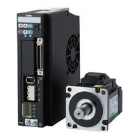
AC SERVO MOTOR and SERVO DRIVE
Brand:
Nidec
| Category:
Servo Drives
| Size: 32 MB
Table of Contents
Overview
3
Contents
4
Table of Contents
5
Before Use
7
Important Safety Instructions
8
Safety Precautions
8
Electrical Hazards
9
Responsibility
9
Motor
10
Environmental Limits
10
Mechanical Brake Control
10
Access to Equipment
10
Adjusting Parameters
11
Electromagnetic Compatibility (EMC)
11
Installation and Wiring
12
Operation
12
Additional Precautions
13
Maintenance and Inspection
13
Other Considerations and Precautions
16
Rating
17
Safety Standards
17
Maintenance
19
Check Items Upon Unpacking
20
Drive Label
21
Motor Label
21
Product Label
21
Danger Signs
22
Electric Shock Warning
22
Hot Surface Warning
22
No Impact/No Disassembly Label
22
Specifications
24
Models
25
Motor
25
Names of Parts
26
Specifications
27
Encoder
41
Specifications
41
Drive
42
Drive
43
Notice
49
Overload Detection Feature
50
Dimensions
51
Preparation
53
Dust-Proof and Waterproof
54
Installation and Operating Environment
54
Precautions
54
Installation Precautions
55
Motor Installation
55
Shock and Impact Force
55
Connection with Machines
56
Countermeasure for Oil and Water
56
Stress to the Cables
56
Types of Mounting and Oil Seal
56
Drive Installation
57
Mounting Orientation and Clearance
57
Mounting Drives
58
System Wiring
59
AC Supply
61
Cables
64
Circuit Breaker
64
Connecting Equipment and Recommended Peripherals
64
Control Power
64
Braking Resistor
65
EMC Noise Filter
65
Surge Absorber
65
Emergency Stop Brake
66
Grounding
66
Wiring to the Connectors
67
Motor Connector Pinout
67
Drive Connectors and Pinouts
69
Accessory Connector
72
Connector Parts
72
Stripping Cables with Recommended Tools
72
Connecting the Connectors
73
Disconnecting the Connectors
73
Wire Connection
74
Wire Disconnection
74
Recommended Cable Wires
75
List of Timing Diagrams
76
Timing Diagram Overview
76
Timing Diagrams
77
Turning the Power on
77
Servo off
78
Alarm Occurs
81
Deceleration Stop Behaves as Follows Depending on the Error Type
81
Timing of MBRK Turning off
81
Alarm Reset (Servo ON)
82
Alarm Reset (Servo OFF)
83
Brake Release
84
Deceleration Stop: Timing for Engaging Brake
84
Emergency Stop
85
Upon Alarm Clear, if Deceleration Stop
85
Deceleration Stop Status During
86
Deceleration Stop: Deceleration Stop Status During
86
Delay Time for Quick Stop Complete
87
Connections
88
Analog Command
89
Internal Command
89
Introduction
89
Pulse Train Command
89
CN1 Connector Wiring Example
90
Differential, Standard I/O Setting
91
General-Purpose Output
91
Position Control Mode
91
Pulse Train Command
91
Pulse Train Command, Differential, Standard I/O Configuration
92
Command Input
93
Differential, I/O Setting Option 1
93
Encoder Output
93
RS-485 Communication
93
Differential, I/O Setting Option 2
95
24V Open Collector, Standard I/O Configuration
97
5V Open Collector, Standard I/O Configuration
99
Internal Position Command
101
Standard I/O Configuration
101
Optional I/O Configuration
103
Internal Position Command, Optional I/O Configuration
104
Analog Velocity Command
105
Velocity Control Mode
105
Internal Velocity Command
107
Analog Torque Command
109
Torque Control Mode
109
Descriptions of CN1 Connector Signals
111
General-Purpose Input
112
General-Purpose Output
120
Command Input
127
Encoder Output
130
Communication
131
Interface Circuit of CN1 Connector
132
24V Open Collector
134
5V Open Collector
134
Connection to Pulse Train Command Signal
134
Differential
134
Connection to Analog Command Signal
135
If Isolated
135
If Not Isolated
135
Connection to Encoder Output Circuit
136
Connection to RS-485 Circuit
137
Settings
138
Parameter Tuning Method
139
Display Panel
140
MODE Button
140
Setup Panel
140
Setup Panel Features
140
Displaying a Number with 6 or more Digits
141
Selecting the Digit to Edit
141
Character Table for 7-Segment LED Display
142
Using the Setup Panel
142
Alarm Display Mode
143
Main Menu
143
Status Display Mode
143
Turn the Control Power on
143
I/O Status
145
Control Component Temperature
146
Pulse Train Command Input
146
Pulse Train Command Input (Speed)
146
ABS Position Command
147
ABS Position Feedback
147
Command Position
147
Positioning Status
147
ABS Position Error
148
Position Command Value
148
Position Error
148
Position Feedback
148
Speed Command Setting
149
Speed Error
149
Speed Feedback
149
Torque Command Value
149
Encoder Rotor Mechanical Angle (Multi-Turn)
150
Encoder Rotor Mechanical Angle (Single Turn)
150
Estimated Inertia Ratio
150
Load Factor
150
Encoder Battery Voltage
151
Encoder Communication Retry Count
151
Encoder Data Error Counter
151
Encoder Temperature
151
Regeneration Control Output
152
Regeneration Status
152
Regeneration Voltage Threshold
152
Regeneration Voltage Warning
152
AC Supply Power Voltage
153
Model Code
153
Serial Number
153
List of Alarms
155
List of Warnings
155
Parameter Setting Mode
156
Position Control Mode Only
157
Quick Tuning Mode
157
Auto Tuning Mode
158
Parameter Saving Mode
160
Auxiliary Function Mode
161
JOG Operation
162
JOG Operation Related Parameters
162
Modes and Conditions that Allow JOG Operation
162
Clear Encoder
163
Clear Parameter
163
Connecting Drive and PC
164
System Requirements for Digitax SF Connect
164
Overview of the Parameter List
165
Parameters
165
Characteristics of Parameters
166
Common
167
RS-485 Communications
167
Warning/Error Detection
167
Homing
169
Positioning Complete
169
Command Mode
171
Control Mode
171
Details of Parameters
171
Enable Switch
172
Minimum Response Time
172
Parity
172
Stop Bit
172
Alarm Output Timing
173
Input Pulse Form
173
Warning Latch Time
173
Input Filter
174
Input Logic
174
Interpolation with Pulse Ratio
174
Rotational Direction
174
Input Filter (Denominator)
175
Input Filter (Numerator)
175
Ratio (Denominator)
175
Ratio (Numerator)
175
CCW Speed Limit (Denominator)
176
CCW Speed Limit (Numerator)
176
Input Gain (Denominator)
176
Input Gain (Numerator)
176
Offset Tuning Method
177
Offset Value
177
Determination Method
178
Feed Forward Delay Compensation
179
Position Command Filter
179
Select Switch
179
Limit Switch Input: Setup
180
Detection Criteria - Range
181
Detection Criteria - Speed
181
Detection Criteria - Command Input
182
Detection Delay Time
182
High Frequency Gain
183
Notch Frequency
183
Notch Width
183
Notch Depth
184
Smoothing Filter
184
Smoothing Filter - Moving Average Time
184
Smoothing 1 - Moving Average Counter
185
Smoothing 2 - Moving Average Counter
185
Selection
186
Delay Time
188
Value
188
Damping Ratio
189
Inertia Ratio
189
Inertia Ratio Upper Limit
189
Items
190
Mode Switch
190
Position Control Mode - Control Gain Set
191
Position Control Mode - Inertia Conditions
192
Position Control Mode - Control Level
193
Position Control Mode - Control Gain 1
194
Position Control Mode - Control Gain 2
194
Position Control Mode - Gain FF Compensation 1
195
Position Control Mode - Gain FF Compensation 2
195
Control Gain Set - Upper Limit
196
Control Gain Set Automatic Enable Switch
196
Position Control Mode - Integral Gain
196
Control Gain Set - Tuning Constant
197
Velocity Control Mode - Control Gain Set
197
Velocity Control Mode - Control Gain 1
198
Velocity Control Mode - Control Level
198
Switch
199
Velocity Control Mode - Gain FF Compensation 1
199
Velocity Control Mode - Integral Gain
199
Torque Limit Output
200
Value 1
200
Value 2
200
Low-Pass Filter
201
Notch Filter
201
Speed Limit
201
Torque Command Limit
201
Low-Pass Filter - Auto Setting
202
Low-Pass Filter - Time Constant
202
Notch Filter - Depth
203
Notch Filter - Frequency
203
Notch Filter - Width
203
Notch Filter 2 - Depth
204
Notch Filter 2 - Frequency
204
Notch Filter 2 - Width
204
Method (Upon Servo Off)
205
Release Conditions
205
Warning Output
206
Warning Output Timing
206
Cancellation Speed
207
Operating Time
207
Smoothing Filter - Moving Average Counter
208
Brake Engagement - Timing
209
Short Brake Operation after a Stop
209
Method (When Alarm Is On)
210
Brake Engagement - Delay Time
211
Brake Engagement - Rotational Speed
211
DBRK Output after Stopping
211
Deceleration Time
212
Extention Time
212
Servo OFF: Delay Time
212
Battery Voltage Drop Detection Switch
213
Overheat Detection Switch
213
Using this Parameter in Absolute Systems
213
Battery Voltage Drop Detection - Value
214
Overheat Detection - Value
214
Pulse Ratio (Denominator)
215
Pulse Ratio (Numerator)
215
Error Detection - Delay Time
216
Error Detection - Frequency Upper Limit
216
CCW Torque Limit (Denominator)
218
CCW Torque Limit (Numerator)
218
Direction of Rotation
219
Maximum Rotational Speed of Motor
224
Operation Mode
225
Overflow Detection
225
Encoder Z-Phase Selection
226
Home Reference Signal Selection
226
Point Table - Point Number Output Method
226
Re-Detection of Home Position Sensor
227
Point Table - Motion of Point No.0
229
Sensor Polarity
229
Creep Speed Enable Switch
230
Acceleration/Deceleration Time
231
Amount of Home Position Shift
231
Creep Speed
231
Rapid Speed
231
Home Position Data
232
Time to Detect Press Stopper
232
Torque Command Limit Value
232
Z-Phase Disabled Distance
232
Point Table
233
Acceleration Time
234
Dwell Time
234
Rotational Speed
234
Point Table Parameter List
235
Operation
236
Configuring Operating Mode
237
Position Control
237
Torque Control
237
Velocity Control
237
Configuring Operatin G Mode
238
Deceleration Stop
238
Limit Switch Input
238
Related to Parameter
238
Configuring Parameters
239
Position Control Mode
241
Pulse Train Command
241
Optional Parameters
242
Input Pulse Form and Parameter Setting
243
Positive or Negative Pulse
243
Pulse and Direction
243
Quadrature Phase Difference Pulse
243
Precautions for Testing
244
Testing Procedure
244
Analog Velocity Command
245
Required Parameters
245
Velocity Control Mode
245
Configuration of Parameter No.62.0 and Rotational Direction of Motor
246
Example of Input Gain Configuration
246
Example of Speed Limit Configuration
246
Internal Velocity Command
248
Analog Torque Command
250
Torque Control Mode
250
Internal Position Command(Point Table
253
Position Control Mode
253
Creating Point Table
255
Command Method
256
Rotation Speed
256
Running Operation
257
If You Start with a Point Number that Is “Disabled”
259
Valid or Invalid
259
Operation by User I/O
261
Example of Point Table Setting (Single-Motion)
262
Timing Diagram and Point Table Items
262
Example of Operation 1 Single-Motion Positioning
263
Continuous Positioning Motion
264
Press Motion
267
Homing Methods
270
If You Changed the Command Paired-Pulse Ratio Value
270
If You Execute Homing by Using Encoder Z-Phase
270
Types of Homing
270
Homing with User I/O Input
271
Types of Homing Motion
274
Pinout Diagram
90
Tuning
284
Introduction
285
Overview
285
Control Block Diagram
287
Tuning Procedure
290
Overview
291
Position Control Mode
291
Quick Tuning on Digitax SF Connect
291
Final Tuning: Position Control Mode
295
Quick Tuning on Setup Panel
297
Velocity Control Mode
300
Auto Tuning on Digitax SF Connect
301
Final Tuning: Velocity Control Mode
303
Auto Tuning on Setup Panel
305
Tuning Parameters
309
Tuning
309
Inertia Condition
309
Control Gain Set
310
Mode Switch
311
Tuning Items
311
Final Tuning
312
Inertia Ratio
312
Position Control Mode: Control Gain 1
313
Position Control Mode: Control Gain 2
314
Velocity Control Mode: Control Gain 1
315
Position Control Mode: Gain FF Compensation 1
316
Position Control Mode: Gain FF Compensation 2
316
Integral Gain
318
Position Command Filter
319
Position Command Smoothing Filters 1 and 2
321
Position Command Notch Filter
322
Position Command Γ-Notch Filter
323
Torque Command Filter
324
Torque Command Filter: Notch Filter
325
Torque Command Low-Pass Filter
326
Using Digitax SF Connect to Measure Vibration Frequency (FFT)
327
Using Digitax SF Connect to Measure Vibration Frequency
327
Troubleshooting
330
Checking Warnings and Alarms
331
Using the Setup Panel
331
Using Digitax SF Connect
333
Warnings and Remedies
334
Warning Output
334
Warning Details
335
Alarms and Remedies
337
Alarms and Remedies
338
Alarm Details
338
Troubleshooting
346
Problem 1(No Display on the Setup Panel
347
Problem 3(No Motor Rotation
349
Problem 4(Unstable Motor Motion
350
Problem 5(Positional Disturbance
351
Problem 6(Vibration and Abnormal Noise
352
Appendices
354
Absolute System
355
Overview
355
System Configuration
356
Backup Battery
357
Absolute Encoder Cable
359
Initializing Absolute Encoder
360
Obtaining Absolute Data
364
Alarm
366
Function
368
Emergency Stop
368
Technical Data
369
Drive Circuit Block Diagram
369
Status Display
370
Introduction
370
Details of each Status Variable
372
How to Set Pulse Train Command: Input Filter (33.0)
385
How to Set Pulse the Train Command: Input Filter (33.0)
385
Advertisement
Advertisement
Related Products
Nidec Control Techniques Digitax-SF DA2YZ23
Nidec Control Techniques Digitax-SF DA2Z123
Nidec Control Techniques Digitax-SF DA22423
Nidec Control Techniques Digitax-SF DA21223
Nidec Control Techniques Digitax-SF DA23823
Nidec Control Techniques Digitax-SF DA24A23
Nidec Control Techniques Digitax-SF DA26B23
Nidec Control Techniques Digitax-SF Series
Nidec Control Techniques Digitax-SF MY500 2 Series
Nidec Control Techniques Digitax-SF MY101 2 Series
Nidec Categories
Measuring Instruments
Industrial Equipment
DC Drives
Controller
Test Equipment
More Nidec Manuals
Login
Sign In
OR
Sign in with Facebook
Sign in with Google
Upload manual
Upload from disk
Upload from URL