
Subscribe to Our Youtube Channel
Related Manuals for ThermoFisher Scientific Vanquish VC-D50


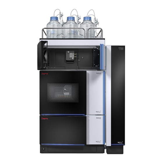
Summary of Contents for ThermoFisher Scientific Vanquish VC-D50
- Page 1 thermo scientific Vanquish Fluorescence Detectors VC-D50, VC-D51, VF-D50, VF-D51 Operating Manual 4820.7901-EN Revision 2.0 • December 2019...
- Page 2 Copyright © 2019 Thermo Fisher Scientific Inc. All rights reserved. Original Operating Manual The hardware descriptions in this manual revision refer to devices VC-D50-A, VC-D51-A, VF-D50-A, VF-D51-A. Trademarks Acrobat, Adobe, and Adobe Reader are trademarks of Adobe Systems Incorporated. Microsoft and Windows are trademarks of Microsoft Corporation. Torx is a trademark of Acument Intellectual Properties, LLC.
- Page 3 Contacting Us Contacting Us There are several ways to contact us: Ordering Information For ordering information or sales support for HPLC products, contact your local Thermo Fisher Scientific sales organization. For contact information, go to Contact Us on http://www.thermofisher.com. Technical Assistance For technical support for HPLC products, contact your local Thermo Fisher Scientific support organization.
- Page 4 Contacting Us Page 4 Fluorescence Detectors (VC-D50, VC-D51, VF-D50, VF-D51) Operating Manual...
-
Page 5: Table Of Contents
Contents Contents 1 Using this Manual .............. 11 About this Manual .................... 12 Conventions...................... 13 1.2.1 Safety Messages.................. 13 1.2.2 Special Notices and Informational Notes .......... 13 1.2.3 Typographical Conventions .............. 14 Reference Documentation ................... 15 2 Safety.................. 17 Safety Symbols and Signal Words................. 18 2.1.1 Safety Symbols and Signal Words in This Manual ........ - Page 6 Contents Leak Detection...................... 40 Operation ...................... 41 4 Unpacking .................. 43 Unpacking...................... 44 Scope of Delivery.................... 46 5 Installation................. 47 Safety Guidelines for Installation ................. 48 Installing the Device ..................... 49 Site Requirements .................... 51 5.3.1 Power Considerations ................ 51 5.3.2 Power Cord.................... 51 5.3.3 Condensation ................... 52 Accessing the Interior Components .............. 53 Setting Up the Hardware.................. 54 5.5.1...
- Page 7 Contents 6 Operation................... 89 Introduction to this Chapter................. 90 Safety Guidelines for Operation ................ 91 Control Elements .................... 92 6.3.1 Keypad...................... 92 6.3.2 Status Indicators.................. 93 Power On/Off Control .................. 95 Preparing the Device for Operation .............. 96 Guidelines for Use of Flow Cells ................ 98 Operational Modes of the Detector .............. 99 6.7.1 Single-Channel Mode ................
- Page 8 Contents Routine and Preventive Maintenance............... 128 7.4.1 Maintenance Plan .................. 128 7.4.2 Cleaning or Decontaminating the Device.......... 128 7.4.3 Predictive Performance................ 130 7.4.4 Monitoring the Lamp Age .............. 131 Performing a Wavelength Calibration ............... 132 Performing a Wavelength Validation .............. 134 Flow Cell ......................
- Page 9 Contents 10 Accessories, Consumables and Replacement Parts .... 171 10.1 General Information .................. 172 10.2 Ship Kit....................... 173 10.3 Optional Accessories .................. 174 10.4 Consumables and Replacement Parts ............... 175 11 Appendix.................. 177 11.1 Compliance Information.................. 178 11.1.1 Declarations of Conformity .............. 178 11.1.2 WEEE Compliance ..................
- Page 10 Contents Page 10 Fluorescence Detectors (VC-D50, VC-D51, VF-D50, VF-D51) Operating Manual...
-
Page 11: Using This Manual
• Using this Manual 1 Using this Manual This chapter provides information about this manual, the conventions used throughout the manual, and the reference documentation that is available in addition to this manual. Fluorescence Detectors (VC-D50, VC-D51, VF-D50, VF-D51) Page 11 Operating Manual... -
Page 12: About This Manual
• Using this Manual About this Manual This manual describes the functional features and operating principle of your Vanquish™ device and provides instructions for installation, set up, start up, shut down, operation, maintenance and troubleshooting. The layout of this manual is designed to provide quick reference to the sections of interest to the user. -
Page 13: Conventions
• Using this Manual Conventions This section describes the conventions that are used throughout this manual. 1.2.1 Safety Messages The safety messages and precautionary statements in this manual appear as follows: • Safety messages or precautionary statements that apply to the entire manual and all procedures in this manual are grouped in the Safety chapter. -
Page 14: Typographical Conventions
• Using this Manual 1.2.3 Typographical Conventions These typographical conventions apply to the descriptions in this manual: Data Input and Output • The following appears in bold type: Input that you enter by the keyboard or that you select with the ¨... -
Page 15: Reference Documentation
• Using this Manual Reference Documentation In addition to this operating manual, other documentation is available for reference. Hardware Documentation Additional hardware documentation includes the following: • Operating manuals for the other modules of the Vanquish system A printed version of the manual is shipped with the device. •... - Page 16 • Using this Manual TIP The Chromeleon Help and documents are included in the software shipment. Third-Party Documentation Refer also to the user documentation provided by the manufacturers of third-party components and materials, for example, Safety Data Sheets (SDSs). Page 16 Fluorescence Detectors (VC-D50, VC-D51, VF-D50, VF-D51) Operating Manual...
-
Page 17: Safety
• Safety 2 Safety This chapter provides general and specific safety information and informs about the intended use of the device. Fluorescence Detectors (VC-D50, VC-D51, VF-D50, VF-D51) Page 17 Operating Manual... -
Page 18: Safety Symbols And Signal Words
• Safety Safety Symbols and Signal Words 2.1.1 Safety Symbols and Signal Words in This Manual This manual contains safety messages to prevent injury of the persons using the device. The safety symbols and signal words in this manual include the following: Always be aware of the safety information. -
Page 19: Safety Symbols On The Device
• Safety 2.1.3 Safety Symbols on the Device The table lists the safety symbols that appear on the device or on labels affixed to the device. Follow the safety notices in this manual to prevent the risk of operator injury or damage to the device. Symbol Description Indicates a potential hazard. -
Page 20: Intended Use
• Safety Intended Use The device is intended to be part of the Vanquish system. The intended use of the Vanquish system is to analyze mixtures of compounds in sample solutions. The device is for use by qualified personnel and in laboratory environment only. -
Page 21: Safety Precautions
• Safety Safety Precautions 2.3.1 General Safety Information All users must observe the general safety information presented in this section and all specific safety messages and precautionary statements elsewhere in this manual during all phases of installation, operation, troubleshooting, maintenance, shutdown, and transport of the device. If the device is used in a manner not specified by Thermo Fisher Scientific, the protection provided by the device could be impaired. -
Page 22: Personal Protective Equipment
• Safety Installation Only skilled personnel are permitted to install the device and to establish the electrical connections according to the appropriate regulations. • Thermo Fisher Scientific recommends always having service personnel certified by Thermo Fisher Scientific perform the installation (for brevity, referred to as Thermo Fisher Scientific service engineer). -
Page 23: Electrical Safety Precautions
• Safety Gloves To protect you from harmful liquids and avoid personal injury during maintenance or service, put on appropriate protective gloves. 2.3.4 Electrical Safety Precautions WARNING—Electric Shock or Damage to the Device High voltages are present inside the device that could cause an electric shock or damage to the device. - Page 24 • Safety WARNING—Hazardous Substances Solvents, mobile phases, samples, and reagents might contain toxic, carcinogenic, mutagenic, infectious, or otherwise harmful substances. The handling of these substances can pose health and safety risks. • Be sure that you know the properties of all substances that you are using.
- Page 25 • Safety WARNING—Hazardous Vapors Mobile phases and samples might contain volatile or flammable solvents. The handling of these substances can pose health and safety risks. • Avoid accumulation of these substances. Make sure that the installation site is well ventilated. •...
-
Page 26: In Case Of Emergency
• Safety 2.3.6 In Case of Emergency WARNING—Safety Hazard In case of emergency, disconnect the device from the power line. Page 26 Fluorescence Detectors (VC-D50, VC-D51, VF-D50, VF-D51) Operating Manual... -
Page 27: Solvent And Additive Information
• Safety Solvent and Additive Information 2.4.1 General Compatibility To protect optimal functionality of the Vanquish system, observe these recommendations on the use of solvents and additives: • The system must be used with reversed-phase (RP) compatible solvents and additives only. •... -
Page 28: Allowed Concentrations
• Safety 2.4.3 Allowed Concentrations Allowed concentrations (standard system configuration): System Chloride Buffer Remarks (Standard Configuration) Vanquish Core 0.1 mol/L 1 mol/L or • High chloride concentration: or less less The application time should be as short as possible. Flush the Vanquish Horizon 1 mol/L or system thoroughly after these... -
Page 29: Compliance Information
• Safety Compliance Information Thermo Fisher Scientific performs complete testing and evaluation of its products to ensure full compliance with applicable domestic and international regulations. When the device is delivered to you, it meets all pertinent electromagnetic compatibility (EMC) and safety standards as described in this manual. - Page 30 • Safety Page 30 Fluorescence Detectors (VC-D50, VC-D51, VF-D50, VF-D51) Operating Manual...
-
Page 31: Device Overview
• Device Overview 3 Device Overview This chapter introduces you to the device and the main components. Fluorescence Detectors (VC-D50, VC-D51, VF-D50, VF-D51) Page 31 Operating Manual... -
Page 32: Detector Features
• Device Overview Detector Features The device comprises the following main features: • A xenon flash lamp for the complete excitation wavelength range from 200 nm to 880 nm as the light source of the device • An optional second photomultiplier tube (PMT) to extend the emission wavelength range to the near-infrared spectral region (up to 900 nm) without any loss in sensitivity in the UV/VIS spectral region... -
Page 33: Operating Principle
• Device Overview Operating Principle Fluorescence detectors are optical detectors. In a fluorescence detector, the sample is exposed to light at a defined wavelength. The light is absorbed by the sample substance and causes the substance to be placed in an excited state (excitation). As the sample substance returns to its ground state, it emits light at a higher wavelength (emission). - Page 34 • Device Overview Fluorescence is used, for example, in highlighters or in whitening agents (optical brighteners). Fluorescent paint used in highlighters absorbs in the blue and near, non-visible ultraviolet range of the daylight and emits light at a longer wavelength (typically blue-green, yellow and red). As shown in the following figure, the light beam from the xenon flash lamp (no.
- Page 35 • Device Overview Figure 3: Optics Setup (schematic) Component Description Xenon flash lamp Light source for the UV to near-infrared wavelength range Lamp optics Focuses the light beam emitted from the xenon flash lamp so that the beam passes through the excitation monochromator Excitation Lets only light with the selected excitation wavelength...
-
Page 36: Interior Components
• Device Overview Interior Components The user-accessible components of the device are located directly behind the front doors: Figure 4: Interior view (here with flow cell installed) Description Cooling air intake Keypad with status indicators Flow cell Leak tray with leak sensor Partition panel The recesses in the partition panel are used to route capillaries with the help of special plugs. -
Page 37: Flow Cell
• Device Overview Flow Cell The detector design allows easy access to the flow cell on the interior front. Figure 5: Flow cell (example) Description Flow cell screws - Used to mount the flow cell to the detector. Flow cell label Outlet - Used to connect the waste line. - Page 38 • Device Overview Temperature Control The flow cells are equipped with a temperature control unit. Flow cell and heat exchanger can be heated to a user-defined temperature. The heat exchanger helps to adapt the temperature of the mobile phase to the flow cell temperature before the mobile phase enters the optical flow path within the flow cell.
-
Page 39: Lamp
• Device Overview Lamp The light source is a xenon flash lamp. Figure 6: Xenon flash lamp • The lamp is turned on when data acquisition starts, and automatically turned off after data acquisition was stopped to extend its lifetime. • The flash frequency of the lamp varies, depending on the selected lamp mode. -
Page 40: Leak Detection
• Device Overview Leak Detection Leaks are a potential safety issue. The leak sensor inside the device monitors the device for liquid leaks from the flow connections. The liquid is collected in the leak tray and guided to the drain port. From the drain port, the liquid is discharged to waste through the drain system of the Vanquish system. -
Page 41: Operation
• Device Overview Operation The device is designed to be operated from a computer configured with the Chromeleon Chromatography Data System (CDS). The Chromeleon software provides complete instrument control, data acquisition, and data management. For a basic description of instrument control and automated sample analysis with the Chromeleon software, refer to the Vanquish System Operating Manual. - Page 42 • Device Overview Page 42 Fluorescence Detectors (VC-D50, VC-D51, VF-D50, VF-D51) Operating Manual...
-
Page 43: Unpacking
• Unpacking 4 Unpacking This chapter provides information for unpacking the device and informs you about the scope of delivery. Fluorescence Detectors (VC-D50, VC-D51, VF-D50, VF-D51) Page 43 Operating Manual... -
Page 44: Unpacking
• Unpacking Unpacking Damaged Packaging, Defective on Arrival Inspect the shipping container for signs of external damage and, after unpacking, inspect the device for any signs of mechanical damage that might have occurred during shipment. If you suspect that the device may have been damaged during shipment, immediately notify the incoming carrier and Thermo Fisher Scientific about the damage. - Page 45 • Unpacking Figure 7: Carrying handles on the device Component Carrying handles Attachment screw (one on each carrying handle) 4. Place the device on a stable surface. 5. If applicable: Remove any additional packing material. Leave any protective films attached to the surfaces of the device until it is properly positioned in the system stack.
-
Page 46: Scope Of Delivery
• Unpacking Scope of Delivery The following items are included in the delivery: • Detector • Ship Kit • Operating manual • Power cord For information on contents of the ship kit or reordering parts, see Accessories, Consumables and Replacement Parts (} page 171). -
Page 47: Installation
• Installation 5 Installation This chapter specifies the requirements for the installation site and describes how to set up, install, and configure the device in the Vanquish system and in the chromatography software. Fluorescence Detectors (VC-D50, VC-D51, VF-D50, VF-D51) Page 47 Operating Manual... -
Page 48: Safety Guidelines For Installation
• Installation Safety Guidelines for Installation Pay attention to the following safety guidelines: Observe all warning messages and precautionary statements presented Safety Precautions (} page 21). CAUTION—Heavy Load, Bulky Device The device is too heavy or bulky for one person alone to handle safely. To avoid personal injury or damage to the device, observe the following guidelines: •... -
Page 49: Installing The Device
• Installation Installing the Device The Vanquish system is installed and set up by a Thermo Fisher Scientific service engineer, including all modules and options or parts shipped with them. The service engineer checks that the installation is correct and that the Vanquish system and modules operate as specified. - Page 50 • Installation 7. Recommended: Perform Instrument Installation Qualification. In the Chromeleon software, a wizard is available to guide you through the qualification process. On the Chromeleon 7 Console: Click Tools > Instrument Qualification > Installation Qualification. Follow the instructions in the Instruments Installation Qualification Operating Instructions.
-
Page 51: Site Requirements
• Installation Site Requirements The operating environment is important to ensure optimal performance of the device. This section provides important requirements for the installation site. Note the following: • Operate the device only under appropriate laboratory conditions. • The device is intended to be part of the Vanquish system. Observe the site requirements for the Vanquish system as stated in the Vanquish System Operating Manual. -
Page 52: Condensation
• Installation WARNING—Electric Shock or Damage to the Device • Never use a power cord other than the power cords provided by Thermo Fisher Scientific for the device. • Only use a power cord that is designed for the country in which you use the device. -
Page 53: Accessing The Interior Components
• Installation Accessing the Interior Components To access the interior components in the device, open the front doors. To allow easy access from the front, the user-accessible components and flow connections in the device are located directly behind the doors. Figure 9: Opening the front doors Fluorescence Detectors (VC-D50, VC-D51, VF-D50, VF-D51) Page 53... -
Page 54: Setting Up The Hardware
• Installation Setting Up the Hardware This section describes how to set up the hardware and provides information about the device connectors and cables. 5.5.1 System Arrangement The device is part of the Vanquish system. The system modules are typically arranged in a system stack, with the arrangement depending on the system configuration. - Page 55 • Installation System with Single Detector Figure 10: Vanquish system, standard configuration (example) Description Solvent Rack Fluorescence detector Autosampler Pump System Base Column Compartment Fluorescence Detectors (VC-D50, VC-D51, VF-D50, VF-D51) Page 55 Operating Manual...
- Page 56 • Installation System with Fluorescence Detector as Second Detector Figure 11: Vanquish system, configuration with two detectors (example) Description Solvent Rack Fluorescence Detector UV/VIS Detector Autosampler Pump System Base Column Compartment Page 56 Fluorescence Detectors (VC-D50, VC-D51, VF-D50, VF-D51) Operating Manual...
-
Page 57: Connecting The Device
• Installation 5.5.2 Connecting the Device Device Connectors The following connectors are provided on the device: Figure 12: Electrical connectors on the right side of the detector Description Rating plate, indicating the serial number, part number, module name, revision number (if any), line and fuse rating, and the manufacturer's address Main power switch (on/off control) Fuse holder... - Page 58 • Installation Description Digital I/O ports (Dig I/O)Allow exchange of digital signals with external instruments Each digital I/O port provides one input and one relay output. For connection and pin assignment information, see Digital I/O (} page 181). USB hub ("A"-type connector) Allows connection to other modules in the Vanquish system USB (Universal Serial Bus) port ("B"...
- Page 59 • Installation 5.5.2.1 Connecting the Interface Cables The connection of the interface cables depends on whether the detector is used as the only detector or as a second detector in the Vanquish system. The Detector is the only Detector in the System Connect the required interface cables to the detector.
- Page 60 • Installation Figure 13: Cable connections in the Vanquish system with fluorescence detector and diode array detector (example) Description System base Pump Sampler Diode array detector Fluorescence detector Column compartment Connection to computer Page 60 Fluorescence Detectors (VC-D50, VC-D51, VF-D50, VF-D51) Operating Manual...
-
Page 61: Installing The Flow Cell
• Installation 5.5.2.2 Connecting the Power Cord NOTICE Condensation in a device can damage the electronics. • Before connecting the devices to the power line, be sure that no condensation is present in the devices. • If you suspect that condensation is present, allow the device to warm up to room temperature slowly. - Page 62 • Installation Parts required Flow cell Preparations 1. Remove the cover from the flow cell opening. To do so, loosen the two finger-tight screws. The screws are captive in the cover and do not need to be removed. TIP Keep the cover to close the flow cell opening when no flow cell is installed in the device, especially when the detector is transported or shipped.
- Page 63 • Installation Follow these steps 1. Insert the flow cell straight into the flow cell opening. Figure 15: Inserting the flow cell 2. Tighten the flow cell screws hand-tight. Fluorescence Detectors (VC-D50, VC-D51, VF-D50, VF-D51) Page 63 Operating Manual...
-
Page 64: Setting Up The Flow Connections
• Installation Setting Up the Flow Connections 5.6.1 General Information and Guidelines When setting up flow connections, follow these rules and recommendations: Flow connections can be filled with hazardous substances. Observe the warning messages and precautionary statements presented in Safety Precautions (} page 21). -
Page 65: Guiding Capillaries And Tubing Through The System
• Installation • Operating switching valves, fraction collectors, mass spectrometers, or a second detector downstream of the flow cell under flow will result in pressure spikes that can destroy the flow cell. If using those devices, you need to install an overpressure relief valve (available as an accessory for the Micro flow cell, opens at 4 MPa (40 bar)). - Page 66 • Installation Figure 16: Tubing chase with tubing guides (left: view from inside, right: view from top) Use for Solvent tubing (up to three solvent lines) Solvent tubing (up to three solvent lines) Wash liquid tubing (seal wash, autosampler needle wash) Detector waste line Tubing brackets are available for holding the tubing in place.
-
Page 67: Installing The Partition Panel Plugs
• Installation 5.6.3 Installing the Partition Panel Plugs There are two types of partition panel plugs available in the detector ship kit. Figure 18: Plugs available for the partition panel Description Plug with slit, for guiding capillaries with small outer diameter, such as uninsulated capillaries. -
Page 68: Connecting Fittings, Capillaries, And Tubing
• Installation Figure 20: Capillary installed in the plug with slit Installing the rotating plug 1. On the detector partition panel, push the rotating plug in the required recess of the partition panel (if not present yet). 2. To open the plug in order to route the capillary through the plug, turn the rotating plug toward the front. - Page 69 • Installation 5.6.4.1 General Guidelines When connecting capillaries and tubing, follow these general recommendations: • Use only the capillaries and tubing (for example, solvent lines or waste tubing) that are shipped with the product or additional or spare capillaries and tubing as recommended by Thermo Fisher Scientific.
- Page 70 • Installation Figure 22: Viper fitting with knurl Description Knurl Capillary Slot 1. Insert the Viper capillary into the connection port. 2. Tighten the connection by the knurl. TIP Note the slot in the knurl. For narrow connections, you can easily remove the knurls from neighboring capillaries through this slot and attach them again later.
-
Page 71: Flow Connections To The Flow Cell
• Installation 5.6.5 Flow Connections to the Flow Cell Connect the inlet capillary and waste line to the flow cell when the flow cell is installed to the device. NOTICE Backpressures that exceed the specified maximum pressure limit of the flow cell can destroy the flow cell. - Page 72 • Installation 2. On the flow cell, remove the plugs from the flow cell inlet and outlet. TIP Store the plugs of the flow cell, for example in the flow cell packaging, to have them easily available when storing or shipping the flow cell.
- Page 73 • Installation Figure 23: Connecting the inlet capillary from the column compartment (example) 1. Route the inlet capillary from the column compartment through the guide hole in the device enclosure. Use the guide hole that is next to the column compartment. TIP Always keep the capillary connection between the column compartment and the flow cell as short as possible to minimize peak dispersion (i.e.
- Page 74 • Installation NOTICE Be aware of the backpressure limit of the flow cell in the Vanquish UV/ VIS detector connected in the flow path before the fluorescence detector. Connect the capillary from the UV/VIS detector directly to the fluorescence detector flow cell inlet. Avoid connecting any additional components in the flow path between the two detectors.
- Page 75 • Installation Figure 25: Securing the capillary behind the capillary clip on the leak tray Description Description Capillary from the flow cell Capillary clip 6. Connect the inlet capillary to the flow cell inlet of the fluorescence detector. Make sure that you secure the inlet capillary appropriately in the capillary clip on the front panel.
-
Page 76: Guiding Liquid Leaks To Waste
• Installation 1. Connect the waste line to the flow cell outlet (OUT) (1). 2. Route the waste line through the top recess (2) in the partition panel. 3. Route the waste line through the tubing guides of the system modules below the detector to the Vanquish system base (3). -
Page 77: Determining The Pressure Inside The Flow Cell
• Installation Determining the Pressure inside the Flow Cell All modules, capillaries and waste lines downstream of the flow cell contribute to the pressure inside the flow cell. If you attach additional modules such as detectors, fraction collectors or a mass spectrometer in the flow path after the flow cell, make sure that the pressure within the flow cell does not exceed its pressure specification. -
Page 78: Measuring The Backpressure Of The Waste Line
• Installation 3. Determine the backpressure of the transfer capillary and the additional module (see Determining the Backpressure of the Transfer Capillary and the Additional Module (Without Flow Cell) (} page 81)). Flow path: Pump – autosampler – column – additional module (- waste line) 4. - Page 79 • Installation Figure 27: Measuring the backpressure of the waste line Description Description Detector Column Flow cell Waste container Outlet port of the flow cell Second detector Inlet port of the flow cell Waste line The description below assumes that the Vanquish system is set up as described in the System Operating Manual.
-
Page 80: Measuring The Vanquish System Backpressure (Without Flow Cell)
• Installation 5.7.2 Measuring the Vanquish System Backpressure (Without Flow Cell) This procedure describes how to measure the Vanquish system backpressure including, for example, the column, detector inlet capillary and the waste line (p1). Figure 28: Measuring the Vanquish system backpressure (without flow cell) Description Description... -
Page 81: Determining The Backpressure Of The Transfer Capillary And The Additional Module (Without Flow Cell)
• Installation 7. When the system pressure has stabilized, read the system pressure in Chromeleon and write down the value for p1. p1: Pressure drop at the column, detector inlet capillary and the waste line 8. Stop the pump flow. See also Flow Connections to the Flow Cell (} page 71) 5.7.3... - Page 82 • Installation 1. Turn on the additional module(s) in the flow path after the flow cell. Refer to the Operating Manuals for these modules. 2. Disconnect the waste line from the union connector. 3. Only if a second detector is used: Connect the waste line to the outlet port of the second detector.
-
Page 83: Determining The Backpressure Of The Flow Cell
• Installation See also Flow Cells (} page 168) 5.7.4 Determining the Backpressure of the Flow Cell This procedure first describes how to measure the backpressure of the flow cell (p4) including that of the column, detector inlet capillary and waste line. Afterward, the backpressure of the column, detector inlet capillary and the waste line (p1) is subtracted. -
Page 84: Calculating The Pressure At The Inlet Port Of The Flow Cell
• Installation 5. Stop the pump flow. 6. Calculate the difference between the two measured pressure values: p5 = p4 – p1. p5: Pressure drop at the flow cell p4: Pressure drop at the flow cell including the column, detector inlet capillary and waste line p1: Pressure drop at the column, detector inlet capillary and the waste line... - Page 85 • Installation 1. Calculate p6 = p5 + p3 + p0. p6: Pressure at the inlet port of the flow cell p5: Pressure drop at the flow cell p3: Pressure drop at the transfer capillary and the additional module p0: Pressure drop at the waste line 2.
-
Page 86: Turning On The Device
• Installation Turning On the Device Before turning on the power to a Vanquish system module for the first time, verify that the chromatography software is installed on the data system computer. When the power is turned on, the required USB drivers are automatically found and the Windows™... -
Page 87: Setting Up The Device In The Software
• Installation Setting Up the Device in the Software This manual assumes that the chromatography software is already installed on the data system computer and a valid license is available. For more information about setting up the Vanquish system in the software, refer to the Vanquish System Operating Manual. - Page 88 • Installation Page 88 Fluorescence Detectors (VC-D50, VC-D51, VF-D50, VF-D51) Operating Manual...
-
Page 89: Operation
• Operation 6 Operation This chapter describes the elements for device control, provides information for routine operation and for shutdown. Fluorescence Detectors (VC-D50, VC-D51, VF-D50, VF-D51) Page 89 Operating Manual... -
Page 90: Introduction To This Chapter
• Operation Introduction to this Chapter The information in this chapter assumes that the initial setup of the device has already been completed. If this is not the case, refer to the instructions in Installation (} page 47). For a basic description of instrument control and automated sample analysis with the Chromeleon software, refer to the Vanquish System Operating Manual. -
Page 91: Safety Guidelines For Operation
• Operation Safety Guidelines for Operation When operating the device, pay attention to the following safety guidelines: Observe all warning messages and precautionary statements presented Safety Precautions (} page 21). CAUTION—Hot Surfaces Surfaces inside the device may become hot during operation. Touching hot parts might cause burns. -
Page 92: Control Elements
• Operation Control Elements The device is designed to be operated mainly from a computer running with the chromatography software. In addition, the following elements are available on the device: • Keypad The keypad buttons allow you to perform certain functions directly from the device. -
Page 93: Status Indicators
• Operation INIT The INIT button allows you to perform a basic initialization by determining the start positions of the grating motors and the filter wheel. The LED next to the button indicates the initialization status: Description Off (dark) The detector is not initialized, or turned off. Green, flashing The detector is initializing. - Page 94 • Operation STATUS LED The STATUS LED on the keypad inside the device provides the following information: STATUS LED Description Off (dark) The power to the device is turned off. Green The device is functioning properly. A problem or error has occurred. For the related message, check the Chromeleon Audit Trail.
-
Page 95: Power On/Off Control
• Operation Power On/Off Control The power switch on the device is the main switch for power on/off control. The main power switch is turned on during initial installation of the device. For easier handling, you can use the power button on the front left of the Vanquish system base (system power button) for power on/off. -
Page 96: Preparing The Device For Operation
• Operation Preparing the Device for Operation This section gives information on any additional steps that are required to prepare the device for operation and sample analysis. Before Operating the Device for the First Time Prepare the device for the first-time operation, observing the following: NOTICE Flush the system flow path thoroughly before operating the device for the first time:... - Page 97 • Operation • Warming up (or cooling down) all temperature-controlled devices in the system to the starting temperature. Temperature-controlled devices can be, for example Column compartment and post-column cooler ¨ Sample compartment thermostatting in the autosampler ¨ Flow cell in a fluorescence detector ¨...
-
Page 98: Guidelines For Use Of Flow Cells
• Operation Guidelines for Use of Flow Cells NOTICE Flow cells are sensitive to damage and contamination. • Handle flow cells with care. See Guidelines for Handling Flow Cells (} page 136). • Observe the guidelines below when operating the detector. Operating conditions Observe the specified maximum pressure limit for the flow cell. -
Page 99: Operational Modes Of The Detector
• Operation Operational Modes of the Detector The device provides five operational modes: • Single-channel mode • Multi-channel mode • Zero Order Mode • Single spectrum scan • FL Field Acquisition 6.7.1 Single-Channel Mode A fluorescence detector is usually operated in single-channel mode, that is, a single excitation/emission wavelength pair is measured over time. -
Page 100: Zero Order Mode
• Operation Setting the Multi-Channel Performance In multi-channel mode, you can select a measuring performance (multi- channel performance) to determine whether the measurement is performed faster, but with more noise, or whether minimum noise is required, which means a longer measuring time and lower data collection rate. -
Page 101: Single Spectrum Scan
• Operation For an example of method development using the Zero Order Mode, refer to the Fluorescence Method Development Handbook. To activate the Zero Order Mode in the Chromeleon software, set the EmWavelength property to ZeroOrder. See also Filter Wheel (VF detectors only) (} page 112) 6.7.4 Single Spectrum Scan During a Single Spectrum Scan, the excitation monochromator or... -
Page 102: Fl Field Acquisition
• Operation Emission Scan The wavelength on the excitation monochromator is kept constant, while the emission monochromator scans a wavelength range. The result is an emission spectrum of the sample. Synchronous Scan A user-defined excitation wavelength range is scanned, while the emission wavelength is scanned synchronously with a fixed user-defined offset. - Page 103 • Operation It is not possible to simultaneously acquire chromatograms during FL Field Acquisition . FL Field Acquisition is available in the Chromeleon 7 software only. Use a 3D data field to determine the retention times and optimum emission or excitation wavelengths.
-
Page 104: Important Operating Parameters
• Operation Important Operating Parameters The commands and parameters described in the table should be considered for simple routine operation of the device. You can usually access these parameters from the Chromeleon user interface. If a parameter listed below is not available in the Chromeleon software, consider updating the firmware and Chromeleon version. - Page 105 • Operation Parameter Description Initialize Performs a basic calibration by determining the start position of the grating motors and filter wheel. Execute if the message "Not initialized" appears in the Chromeleon Audit Trail after the detector is turned on. Leak detection Leak detection is enabled as a standard when the device is shipped (Leak Sensor Mode = Enabled).
-
Page 106: Optimizing The Performance Of The Device
• Operation Optimizing the Performance of the Device This section provides information for best performance of the device and gives hints on what you can do to optimize the performance further. Fluorescence Method Development Handbook Basic information about how to optimize the detector performance can be obtained from the following sections of this Operating Manual. -
Page 107: Overview Of Optimization Parameters
• Operation • Observe the general guidelines and recommendations on the use of solvents and additives in the chromatography system. Refer to Use of Solvents and Additives in the Vanquish System Operating Manual. See also Overview of Optimization Parameters (} page 107) Monitoring the Lamp Age (} page 131) 6.9.2 Overview of Optimization Parameters... -
Page 108: Sensitivity (Detector Sensitivity)
• Operation above the UV cutoff of the solvent. For information about the UV cutoff wavelengths of solvents, see UV Cutoff Wavelengths of Solvents (} page 180). • Select an emission wavelength that is at least 20 nm above the excitation wavelength. TIP Chromeleon 7 supports FL Field Acquisition for the fluorescence detector, which facilitates determining the retention times and absorption maxima. - Page 109 • Operation • If the selected sensitivity is too large, the PMT signal is saturated. In this case, the detector automatically reduces the sensitivity. Markers appear in the chromatogram at the beginning and at the end of the saturation (see figure, Sensitivity = 8). If the detector is not saturated any more, the Sensitivity setting before saturation is restored.
- Page 110 • Operation Determining the optimum sensitivity Determine the optimum sensitivity in a separate sample run after you have determined the optimum wavelengths as described below. • Use a sample (standard) with the maximum expected concentration of the analytes. • Select a sensitivity at which a saturation is not expected (for example, 1 or 2).
- Page 111 • Operation Figure 34: MaxPMTSaturation parameter monitoring 5. Repeat steps 3 through 4 for all peaks. 6. Run a sample and read out the MaxPMTSaturation values in the Chromeleon software and evaluate the results: Value What you should do… < 30% Increase the Sensitivity.
-
Page 112: Filter Wheel (Vf Detectors Only)
• Operation 6.9.5 Filter Wheel (VF detectors only) To prevent stray light from reaching the PMT, additional optical edge filters are installed on a filter wheel in the light path between the flow cell and the emission monochromator. This reduces direct scattering of light from the light source. -
Page 113: Pmt (Only If Second Pmt Is Installed)
• Operation wavelength is near the cut-off wavelength of a filter), setting the filter manually may provide better results than the Auto setting. Note the following: The selected emission wavelength must not be more than 15 nm ¨ below the filter wavelength. If you select Open, the filter wheel remains in an open position. - Page 114 • Operation TIP In Multi-Channel mode, the response time and data collection rate are always determined automatically. You can influence these parameters by selecting a different multi-channel performance. Data Collection Rate The data collection rate is the number of data points per second (Hz) that the Chromeleon software collects from the detector and stores as raw data.
-
Page 115: Flow Cell Temperature
• Operation TIP For best possible combinations of data collection rate, response time and peak width, enable the Link data collection parameters check box in the detector settings of the Chromeleon Instrument Method Wizard or Instrument Method Editor. See also Lamp Mode (} page 115) 6.9.8 Flow Cell Temperature... - Page 116 • Operation Extending the lamp lifetime To extend the lamp lifetime, you can do the following: • Turn off the lamp by stopping data acquisition if you are not interested in the baseline. It is not generally required that the lamp remains turned on during the entire chromatographic separation.
-
Page 117: Baseline Behavior
• Operation 6.9.10 Baseline Behavior If wavelengths are switched or the sensitivity, filter wheel, or PMT setting are changed during the method, the chromatogram may show baseline jumps because of the background fluorescence at the new wavelength setting. Three baseline behavior mode settings define how the baseline behaves in these cases: •... -
Page 118: Shutting Down The Device
• Operation 6.10 Shutting Down the Device If the device will not be operated for some time, follow the instructions in this section to shut down the device. TIP The Chromeleon software provides procedures for automatically preparing the chromatography system for shutdown. The procedures include, for example, operations for reducing the flow rate, reducing the temperature in temperature-controlled devices, and turning off the detector lamps. -
Page 119: Long-Term Shutdown
• Operation 6.10.2 Long-Term Shutdown Shutting Down the Device To interrupt operation for a longer period, follow the instructions below. TIP Shutting down the device affects the operation of the system. When shutting down the device, also observe the shutting down instructions for the other Vanquish system modules and take appropriate action (refer to the Operating Manuals for the modules). - Page 120 • Operation Situation after Shutdown If no additive is used If an additive is used Device and flow cell shall Flush the system with Flush the system first with be transported or shipped isopropanol. several volumes of after shutdown methanol and water (50:50) (for example, 1.0 mL/min for 10 minutes with the...
-
Page 121: Restart After Long-Term Shutdown
• Operation Situation Steps Device shall be transported or shipped If one of the modules shall be removed after shutdown from the system stack, turn off all system modules with their main power switch. Pressing the system power button will not be sufficient to turn off the power to the devices completely. - Page 122 • Operation Page 122 Fluorescence Detectors (VC-D50, VC-D51, VF-D50, VF-D51) Operating Manual...
-
Page 123: Maintenance And Service
• Maintenance and Service 7 Maintenance and Service This chapter describes the routine maintenance and the service procedures that the user may perform. Fluorescence Detectors (VC-D50, VC-D51, VF-D50, VF-D51) Page 123 Operating Manual... -
Page 124: Introduction To Maintenance And Service
• Maintenance and Service Introduction to Maintenance and Service This chapter describes the routine maintenance and service and repair procedures that the user may perform. Additional maintenance or service procedures must be performed only by service personnel certified by Thermo Fisher Scientific (for brevity, referred to as Thermo Fisher Scientific service personnel). -
Page 125: Safety Guidelines For Maintenance And Service
• Maintenance and Service Safety Guidelines for Maintenance and Service When performing maintenance or service procedures, pay attention to the following safety guidelines: Observe all warning messages and precautionary statements presented Safety Precautions (} page 21). WARNING—High Voltage High voltages are present inside the device that could cause an electric shock. - Page 126 • Maintenance and Service CAUTION—Hot Surfaces Surfaces inside the device may become hot during operation. Touching hot parts might cause burns. Allow hot surfaces to cool down before starting replacement or maintenance procedures. CAUTION—Hydrostatic Pressure Solvent may spill when you open the flow path. This is due to hydrostatic pressure in the system when the solvent reservoirs are located above the pump outlet.
-
Page 127: General Rules For Maintenance And Service
• Maintenance and Service General Rules for Maintenance and Service For successful maintenance and service procedures, follow these rules and recommendations: • Before starting maintenance or service procedures, shut down the device when instructed to do so. • Use only the replacement parts specifically authorized and qualified for the device by Thermo Fisher Scientific. -
Page 128: Routine And Preventive Maintenance
• Maintenance and Service Routine and Preventive Maintenance Optimum device performance, maximum uptime of the device, and accurate results can be obtained only if the device is in good condition and properly maintained. 7.4.1 Maintenance Plan Perform the maintenance procedures in the table on a regular basis. The frequency given in the table is a suggestion. - Page 129 • Maintenance and Service Decontamination Decontamination is required, for example, when leakage or spillage has occurred, or before service or transport of the device. Use a suitable cleaning detergent or disinfectant to ensure that the treatment renders the device safe to handle. Parts required •...
-
Page 130: Predictive Performance
• Maintenance and Service Preparations 1. Turn off the power to the device and disconnect the power cord from the power source. Follow these steps 1. Wipe the surfaces clean with a clean, dry, soft, lint-free cloth or wipe. If necessary, slightly dampen the cloth or wipe with a solution of lukewarm water and a suitable cleaning detergent. -
Page 131: Monitoring The Lamp Age
• Maintenance and Service 7.4.4 Monitoring the Lamp Age The Chromeleon software supports functions for monitoring the lamp age. This function can help to decide when a lamp is due to be replaced. The flash lamp can produce about 1-1.5x10 flashes before it needs replacement only if the performance of the detector is no longer sufficient. -
Page 132: Performing A Wavelength Calibration
• Maintenance and Service Performing a Wavelength Calibration A simple initialization procedure is performed after power-up of the detector. This requires that a flow cell is installed in the detector. For details, see Power On/Off Control (} page 95). To ensure optimum performance and wavelength accuracy, perform a wavelength calibration using water (Raman measurement). - Page 133 • Maintenance and Service 2. Confirm with OK if you are sure that the above conditions are met. The calibration run may take up to five minutes. The new calibration values are stored in the detector. 3. Perform wavelength validation. See also Performing a Wavelength Validation (} page 134) Fluorescence Detectors (VC-D50, VC-D51, VF-D50, VF-D51)
-
Page 134: Performing A Wavelength Validation
• Maintenance and Service Performing a Wavelength Validation You can validate the wavelength calibration using water (Raman measurement). If validation fails, that is, if the measured values significantly deviate from the calibration values, you can perform a wavelength calibration using water (Raman measurement). The light spectrum of the xenon flash lamp is used to validate the excitation wavelength. - Page 135 • Maintenance and Service 2. Confirm with OK if you are sure that the above conditions are met. The validation run may take up to five minutes. The result ("passed"/"failed") is displayed in the Chromeleon Audit Trail. Passed: The wavelength accuracy is within specification. The ¨...
-
Page 136: Flow Cell
• Maintenance and Service Flow Cell This section describes cleaning and replacement of flow cells. No tools are required to remove and install a flow cell. 7.7.1 Guidelines for Handling Flow Cells NOTICE Flow cells are highly sensitive to dirt and dust. Observe the following notes when handling flow cells: •... - Page 137 • Maintenance and Service Follow these steps CAUTION—Hot surface The flow cell may become hot. Touching a hot flow cell might cause burns. • Touch the flow cell briefly and carefully to find out if it is hot before you remove the flow cell. •...
-
Page 138: Cleaning The Flow Cell
• Maintenance and Service 7.7.3 Cleaning the Flow Cell When When you suspect that eluent or sample components may have deposited on the flow cell windows. Parts required • Flushing and injection kit for flow cells (optional) • HPLC-grade water •... -
Page 139: Installing The Flow Cell
• Maintenance and Service 7.7.4 Installing the Flow Cell Parts required Flow cell Follow these steps 1. Insert the flow cell straight into the flow cell opening. Figure 37: Inserting the flow cell 2. Tighten the flow cell screws hand-tight. 3. Install the capillaries to the flow cell. Follow the instructions in Setting Up the Flow Connections (} page 64). -
Page 140: Replacing The Main Power Fuses
• Maintenance and Service Replacing the Main Power Fuses When Blown fuses Parts required Fuses (2 fuses, 3.15 AT, 250 V AC, slow-blow, 5 x 20 mm) from Fuses Kit Tools required Slotted screwdriver, any size between 3.3 mm and 5.5 mm is appropriate Preparations WARNING—Electric Shock High voltages are present inside the device that could cause an electric shock or damage to the device. - Page 141 • Maintenance and Service 1. Use the screwdriver to remove the fuse holder. 2. Replace the two fuses with new fuses of the specified type and current rating. Always replace both fuses. 3. Reinstall the fuse holder. 4. Reconnect the power cord to the power source and to the device. 5.
-
Page 142: Updating The Device Firmware
• Maintenance and Service Updating the Device Firmware When Updating the device firmware might be required, for example, when a new firmware version is released that adds functionality or solves problems of a previous version. Items required Firmware version/Chromeleon version as appropriate TIP When a new firmware version is released, the new version will be included in the next available Chromeleon version. - Page 143 • Maintenance and Service 3. Monitor the Audit Trail of the Instrument Configuration Manager program to see whether the firmware update was successful or failed. If the firmware update failed, turn the device off and on again ¨ and repeat the firmware update. If the firmware update fails repeatedly, contact Thermo Fisher ¨...
-
Page 144: Replacing The Doors
• Maintenance and Service 7.10 Replacing the Doors When Damage of door TIP The maintenance procedures do not require that you remove the doors. If this should ever be required for a specific reason or procedure, follow the related steps in this section. Parts required Replacement door Follow these steps... - Page 145 • Maintenance and Service 3. To install the door, align the door with the hinges on the housing. Be careful not to clamp tubing or capillaries between the door and the enclosure. 4. Insert the hinges in the groove, by pushing up and slightly turning the door.
-
Page 146: Transporting Or Shipping The Device
• Maintenance and Service 7.11 Transporting or Shipping the Device If you want to transport the device to a new location or if you need to ship the device, first prepare the device for transport and then move or ship the device as required. Follow the instructions in this section. Observe the following safety guidelines: CAUTION—Heavy Load, Bulky Device The device is too heavy or bulky for one person alone to handle safely. -
Page 147: Transporting The Device To A New Location
• Maintenance and Service 4. Remove the flow cell from the device and store it in its packaging. Ensure that you install the flow cell cover to the flow cell opening. Flow cells must be shipped in their original packaging. NOTICE The flow cell opening on the device is sensitive to dust and debris. -
Page 148: Shipping The Device
• Maintenance and Service 7.11.3 Shipping the Device Preparations Prepare the device for transport. See Preparing the Device for Transport (} page 146). Follow these steps 1. Follow the unpacking instructions in this manual in the reverse order. Use only the original packing material and shipping container. If the original shipping container is not available, appropriate containers and packing material can be ordered from the Thermo Fisher Scientific sales organization. -
Page 149: Replacing The Slide-In Module
• Maintenance and Service 7.12 Replacing the Slide-In Module 7.12.1 Removing the Slide-In Module CAUTION—Heavy Load, Bulky Device The device is too heavy or bulky for one person alone to handle safely. To avoid personal injury or damage to the device, observe the following guidelines: •... -
Page 150: Returning The Slide-In Module
• Maintenance and Service Figure 41: Pulling out the slide-in module NOTICE The slide-in module can fall down when pulling it out of the enclosure too far. Pull out the slide-in module just far enough so that you can grasp it on both sides from below. -
Page 151: Installing The Slide-In Module
• Maintenance and Service NOTICE Shipping the slide-in module improperly leads to damage to the device. Always ship the slide-in module as described in this operating manual. CAUTION—Possible Contamination Hazardous substances may have contaminated the device during operation and may cause personal injury to service personnel. •... - Page 152 • Maintenance and Service Follow these steps 1. Push all tubing and capillaries, which are present in the tubing chase of the Vanquish system modules, into the tubing chase. Otherwise, you will not be able to insert the slide-in module properly into the enclosure in the next step.
-
Page 153: Setting Up The Slide-In Module
• Maintenance and Service NOTICE • Verify that the screws are tightened. Pull the slide-in module by the leak tray towards the front and check whether the screws move. If they do not move, the slide-in module is installed properly. •... - Page 154 • Maintenance and Service Page 154 Fluorescence Detectors (VC-D50, VC-D51, VF-D50, VF-D51) Operating Manual...
-
Page 155: Troubleshooting
• Troubleshooting 8 Troubleshooting This chapter is a guide to troubleshooting issues that may arise during operation of the device. Fluorescence Detectors (VC-D50, VC-D51, VF-D50, VF-D51) Page 155 Operating Manual... -
Page 156: General Information About Troubleshooting
• Troubleshooting General Information about Troubleshooting The following features help you to identify and eliminate the source for problems that may arise during operation of the device. TIP For information about operating issues that might occur during the operation of a Vanquish system, refer to the Vanquish System Operating Manual. - Page 157 • Troubleshooting Messages in the Chromeleon Audit Trail are preceded by an icon. The icon identifies the seriousness of the problem (refer to the Chromeleon Help). For possible causes and remedial actions, see Messages (} page 158). Fluorescence Detectors (VC-D50, VC-D51, VF-D50, VF-D51) Page 157 Operating Manual...
-
Page 158: Messages
• Troubleshooting Messages The table lists the most frequently observed messages for the device and provides troubleshooting assistance. Each message consists of a code number and a text. The code number is the unique identifier for the problem while the wording may change. Note the following: •... - Page 159 • Troubleshooting Message and Code Description and Remedial Action Code 89 Liquid leak sensor missing or Verify that the leak sensor is installed and the cable connector is defective. properly connected. Contact Thermo Fisher Scientific Technical Support for assistance if the leak sensor is defective. To operate the device nevertheless, you can disable the leak sensor functionality in the Chromeleon software by setting LeakSensorMode to Disabled.
- Page 160 • Troubleshooting Message and Code Description and Remedial Action Code 8049 Command rejected - close It is not possible to start data acquisition with the front doors open. front door first Close the doors and try again. Code 8051 Flow cell detected. It is A new flow cell was found.
- Page 161 • Troubleshooting Message and Code Description and Remedial Action Code 8111 - Code 8115 Calibration of With x = Name of the component for which calibration failed xx failed. Cause details Raman calibration failed. Remedial actions • Observe the conditions for wavelength calibration (see Performing a Wavelength Calibration (} page 132)) and wavelength validation...
-
Page 162: Operating Issues
• Troubleshooting Operating Issues This section gives an overview of possible operating issues and remedial actions. 8.3.1 Resolving Liquid Leaks When The leak sensor is wet. The leak sensor reports leakage. Parts and additional items required • Replacement part as required •... -
Page 163: Additional Device Operating Issues
• Troubleshooting 4. Allow the sensor to adjust to the ambient temperature for a few minutes. 5. If leakage is no longer reported, you can resume operation. See also Removing the Flow Cell (} page 136) Installing the Flow Cell (} page 139) 8.3.2 Additional Device Operating Issues This section provides additional issues that may arise during operation of the Vanquish device. - Page 164 • Troubleshooting Symptom Possible Cause Remedial Action Spikes Xenon flash lamp old, Contact Technical Support. defective, or not properly installed Fluorescence detector Turn off flow cell temperature control or reduce the flow cell temperature temperature setting. near boiling point of mobile phase Inappropriate device Improper wavelength,...
-
Page 165: Specifications
• Specifications 9 Specifications This chapter provides the physical and performance specifications, including information about the materials used in the flow path of the device. Fluorescence Detectors (VC-D50, VC-D51, VF-D50, VF-D51) Page 165 Operating Manual... -
Page 166: Performance Specifications
• Specifications Performance Specifications 9.1.1 Detector The device performance is specified as follows: Type Specification Optical design Two monochromators with concave holographic gratings and elliptic mirrors for highest efficiency in light transmission Light source Xenon flash lamp (15W); Three different flash frequencies (HighPower, Standard, LongLife) can be selected. - Page 167 • Specifications Type Specification Data collection rate Adjustable: up to 100 Hz (VC-D50, VC-D51) up to 200 Hz (VF-D50, VF-D51 under Chromeleon 7 software in single- channel mode) up to 4 Hz (VF-D50, VF-D51 in multi-channel mode) Sensitivity PMT 1: Raman signal-to-noise ratio: >550 ASTM over the entire lifetime of the lamp;...
-
Page 168: Flow Cells
• Specifications Type Specification Safety features Power-up check of optics and motors (initialization) Monitoring of cooling fans and electronics Leak detection and safe leak handling Flow cell identification and documentation of the flow cell type Good Laboratory Practice (GLP) All system parameters are logged in the Chromeleon Audit Trail. features Functions for monitoring the operating and usage conditions of the device. -
Page 169: Physical Specifications
• Specifications Physical Specifications The physical conditions of the device are specified as follows: Type Specification Range of use Indoor use only Ambient operating 5 °C - 35 °C temperature Ambient storage temperature -20 °C - 45 °C Ambient operating humidity 20% - 80% relative humidity (non-condensing) Ambient storage humidity Maximum 60% relative humidity (non-condensing) Operating altitude... - Page 170 • Specifications Page 170 Fluorescence Detectors (VC-D50, VC-D51, VF-D50, VF-D51) Operating Manual...
-
Page 171: Accessories, Consumables And Replacement Parts
• Accessories, Consumables and Replacement Parts 10 Accessories, Consumables and Replacement Parts This chapter describes the standard accessories that are shipped with the device and the accessories that are available as an option. This chapter also provides information for reordering consumables and replacement parts. -
Page 172: General Information
• Accessories, Consumables and Replacement Parts 10.1 General Information The device must be operated only with the replacement parts and additional components, options, and peripherals specifically authorized and qualified by Thermo Fisher Scientific. Accessories, consumables, and replacement parts are always maintained at the latest technical standard. -
Page 173: Ship Kit
• Accessories, Consumables and Replacement Parts 10.2 Ship Kit The ship kit includes the items listed in the table. The kit content is subject to change and may vary from the information in this manual. See the content list included in the kit for the most recent information about the kit content at the time when the device is shipped. -
Page 174: Optional Accessories
• Accessories, Consumables and Replacement Parts 10.3 Optional Accessories Flow cells and Flow cells accessories Item Part No. Standard flow cell, biocompatible 6079.4230 Micro flow cell, biocompatible 6079.4330 Flushing and injection kit for flow cells, including syringe 6078.4200 Viper capillary, I.D. x length 0.18 x 450 mm, stainless steel 6040.2365 For connecting column and flow cell inlet when using UltiMate 3000 flow cells. -
Page 175: Consumables And Replacement Parts
• Accessories, Consumables and Replacement Parts 10.4 Consumables and Replacement Parts Capillaries and tubing Description Part No. Viper capillary, 350 mm length, MP35N, for connection to the 6042.2340 column Viper capillary, 300 mm length, MP35N, for connection from a 6042.2322 UV/VIS detector to the fluorescence detector Waste line 6036.2425... - Page 176 • Accessories, Consumables and Replacement Parts Description Part No. Power cord, Italy 6000.1040 Power cord, Japan 6000.1050 Power cord, UK 6000.1020 Power cord, USA 6000.1001 Power cord, Switzerland 6000.1030 Page 176 Fluorescence Detectors (VC-D50, VC-D51, VF-D50, VF-D51) Operating Manual...
-
Page 177: Appendix
• Appendix 11 Appendix This chapter provides additional information about compliance, UV cutoff wavelengths, and the use of the digital I/O ports. Fluorescence Detectors (VC-D50, VC-D51, VF-D50, VF-D51) Page 177 Operating Manual... -
Page 178: Compliance Information
• Appendix 11.1 Compliance Information 11.1.1 Declarations of Conformity CE Declaration of Conformity The device has satisfied the requirements for the CE mark and is compliant with the applicable requirements. cTUVus Compliance The cTUVus label on the device indicates that the device has satisfied the requirements for the cTUVus mark. -
Page 179: Weee Compliance
• Appendix 11.1.2 WEEE Compliance This product is required to comply with the European Union’s Waste Electrical & Electronic Equipment (WEEE) Directive. It is marked with the following symbol: Figure 43: WEEE symbol Thermo Fisher Scientific has contracted with one or more recycling or disposal companies in each European Union (EU) Member State, and these companies should dispose of or recycle this product. -
Page 180: Uv Cutoff Wavelengths Of Solvents
• Appendix 11.2 UV Cutoff Wavelengths of Solvents The UV cutoff wavelength is the minimum effective wavelength for the measurement. The mobile phase composition affects its UV cutoff wavelength. In general, mobile phases are solvents, such as, water, acetonitrile, methanol, or other substances. They may also contain salts, such as sodium hydroxide (NaOH). -
Page 181: Digital I/O
• Appendix 11.3 Digital I/O The digital I/O ports (Dig I/O) can be used to exchange digital signals with external devices. Each port provides: • one digital input • one relay output Pin Assignment Figure 44: Digital I/O port Description Not used Relay output — Relay_NC (Normally Closed contact) Ground — GND Digital input — Input... - Page 182 • Appendix Wire Color Signal Name Signal Level Remarks Yellow Digital input — Input (low active): Digital input; reference potential is Input On: 0-0.4 V ground. Note the following: Off: 2.2-5 V • The maximum input voltage at the Pull-up resistor: 47 kΩ to 5 V input must not exceed +5 V with reference to ground.
-
Page 183: Index
Index Index accessories .......... 46, 171 data collection rate ........ 107, 114 optional ............. 174 guidelines .......... 114 ship kit............ 173 decontamination ........ 128, 129 additional detector operating issues.... 163 delivery............. 46 additives ............ 27 detector information .......... 27 additional operating issues ....... 163 audit trail............ 156 sensitivity .......... 108 Audit Trail messages ........ 158 detector waste line .......... 75 autozero ............ 117 determine wavelengths ......... 107... - Page 184 Index exchange ........... 136, 139 flow connections ......... 71 lamp ............ 39, 131 guidelines ............ 98 lamp mode .......... 115 handling ............ 136 replace............ 131 identification chip ........ 37 lamp age............ 131 initial installation......... 61 lamp lifetime .......... 131 install............ 139 lamp mode ............. 107 remove ............ 136 leak detection........... 40, 105 temperature control ........ 38 leak sensor ............. 162 types............ 38 leak sensor mode ........... 105...
- Page 185 Index operating issues .......... 162 safety class ............ 21 operating principle ........... 33 safety glasses............ 22 operation............ 41, 89 safety guidelines control elements ......... 92 case of emergency ........ 26 flow cells ............. 98 electrical safety ........... 23 important parameters....... 104 general ............ 21 interrupt............ 118 general hazards ........... 23 power on/off .......... 95 installation........... 48 safety guidelines ......... 91 maintenance .......... 125...
- Page 186 Index solvent wavelength validation ........ 134 chloride concentration........ 28 WEEE .............. 179 information .......... 27 pH range............ 27 specifications.......... 165 Zero Order Mode ........... 100 performance (detector) ...... 166 performance (flow cells) ...... 168 physical............ 169 spectrum scans.......... 101 Standard lamp mode........ 116 startup.............. 96 status indicator LED bar .......... 92, 93, 156 STATUS LED ........
- Page 187 Index Fluorescence Detectors (VC-D50, VC-D51, VF-D50, VF-D51) Page 187 Operating Manual...
- Page 188 www.thermofisher.com Thermo Fisher Scientific Inc. 168 Third Avenue Waltham Massachusetts 02451...
Need help?
Do you have a question about the Vanquish VC-D50 and is the answer not in the manual?
Questions and answers