Table of Contents
Advertisement
Advertisement
Table of Contents

Related Manuals for Tosot DC Inverter U-match Series


Summary of Contents for Tosot DC Inverter U-match Series
- Page 2 TU18HFI TU18H3O TU24HFI TU24H3O TU30HFI TU30H3O TU36HFI TU36H3O TU42HFI TU42H3O TU48HFI TU48H3O...
- Page 3 To Users Thank you for selecting TOSOT’s product. Please read this instruction manual carefully before installing and using the product, so as to master and correctly use the product. In order to guide you to correctly install and use our product and achieve...
- Page 5 (7) The final right to interpret for this instruction manual belongs to TOSOT. Exception Clauses Manufacturer will bear no responsibilities when personal injury or property loss is caused by the following reasons: (1) Damage the product due to improper use or misuse of the product;...
-
Page 6: Table Of Contents
Contents 1 Safety Precautions ............... 1 2 Outline of the Unit and Main Parts ........3 3 Preparative for Installation ........... 4 3.1 Standard Accessory Parts ............4 3.2 Selection of the Installation Location ..........5 3.3 Connection Pipe Requirement ............. 7 3.4 Electrical Requirement .............. -
Page 7: Safety Precautions
DC Inverter U-match Series Duct Type Unit 1 Safety Precautions This is the safety alert symbol. It is used to alert you to potential personal injury hazards. Obey all safety messages that follow this symbol to avoid possible injury or death. - Page 8 DC Inverter U-match Series Duct Type Unit (12). This appliance is not intended for use by persons (including children) with reduced physical, sensory or mental capabilities, or lack of experience and knowledge, unless they have been given supervision or instruction concerning use of the appliance by a person responsible for their safety.
-
Page 9: Outline Of The Unit And Main Parts
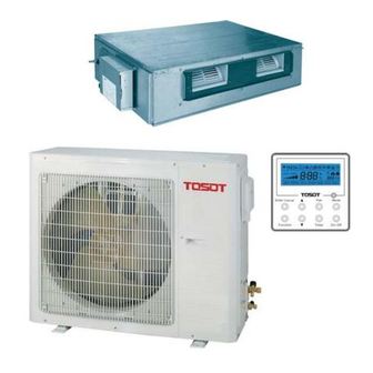
DC Inverter U-match Series Duct Type Unit 2 Outline of the Unit and Main Parts Fig. 2.1 The connection pipe, drain pipe, power cord, and duct for this unit should be prepared by the user. ①. The unit is standard equipped with rectangular duct. -
Page 10: Preparative For Installation
DC Inverter U-match Series Duct Type Unit 3 Preparative for Installation 3.1 Standard Accessory Parts The standard accessory parts listed below are furnished and should be used as required. Table 3.1 Indoor Unit Accessories Name Appearance Q'ty Usage Wired Controller... -
Page 11: Selection Of The Installation Location
DC Inverter U-match Series Duct Type Unit Indoor Unit Accessories Name Appearance Q'ty Usage Sponge To insulate the drain pipe To connect liquid pipe To connect gas pipe Table 3.2 Outdoor Unit Accessories Name Appearance Q'ty Usage To plug the unused... - Page 12 DC Inverter U-match Series Duct Type Unit Fig. 3.1 (4). Install the unit where the drain pipe can be easily installed. (5). The space from the unit to the ceiling should be kept as much as possible so as for more convenient service.
-
Page 13: Connection Pipe Requirement
DC Inverter U-match Series Duct Type Unit Fig. 3.2 3.3 Connection Pipe Requirement The maximum length of the connection pipe is listed in the table below. Do not place the units between which the distance exceeds the maximum length of the connection pipe. -
Page 14: Electrical Requirement
DC Inverter U-match Series Duct Type Unit shall be able to withstand the pressure of 6.0MPa (870psig). The longer the connecting pipe, the lower the cooling and heating effect performs. 3.4 Electrical Requirement Electric Wire Size and Fuse Capacity. Table 3.4... -
Page 15: Installation Of The Unit
DC Inverter U-match Series Duct Type Unit conditions. The communication lines can not be twisted together. For the unit ( ≤ 30k), it’s recommended to use 8m (26-1/4feet) long communication line. Take 2 pieces of power cord of 0.75mm (AWG18) as the communication lines ④. - Page 16 DC Inverter U-match Series Duct Type Unit For the units: 24k~42k For the units: 48k Fig. 4.1 Table 4.1 Unit: mm (inch) Item Model 1035 TU18HFI (37-1/4) (24-3/8) (29) (35-1/8) (40-7/8) (28-3/8) (29) (4-7/8) (10-1/2) TU24HFI 1100 1160 1280 1000...
- Page 17 DC Inverter U-match Series Duct Type Unit 4.1.2 Drilling Holes for Bolts and Installing the Bolts Using the installation template, drill holes for bolts (four holes) (Fig. 4.2). 4.1.3 Installing the Suspension Bolts (1). Install the bolts to the ceiling at a place strong enough to hang the unit. Mark the bolt positions from the installation template.
-
Page 18: Installation Of The Outdoor Unit
DC Inverter U-match Series Duct Type Unit 4.1.4 Leveling The water level test must be done after installing the indoor unit to make the unit is horizontal, as shown below. Fig. 4.7 4.2 Installation of the Outdoor Unit Install the unit where it will not be tilted by more than 5°. -
Page 19: Installation Of The Connection Pipe
DC Inverter U-match Series Duct Type Unit 4.2.2 Condensate Drainage of the Outdoor Unit (Only for the heat pump unit) (Fig. 4.9) (1). It is required to install a drain pipe for the outdoor unit to drain out the condensate water during heating operation (only for the heat pump unit). - Page 20 DC Inverter U-match Series Duct Type Unit 4.3.2 Bending Pipes (1). The pipes are shaped by your hands. Be careful not to collapse them. Fig. 4.11 (2). Do not bend the pipes in an angle more than 90°. (3). When pipes are repeatedly bent or stretched, the material will harden, making it difficult to bend or stretch them any more.
- Page 21 DC Inverter U-match Series Duct Type Unit Centering the pipe against port on the indoor unit turn the flare nut with your hand. Hold the torque wrench at its grip, keeping it in the right angle with the pipe as shown in Fig. 4.13, in order to tighten the flare nut correctly.
- Page 22 DC Inverter U-match Series Duct Type Unit 4.3.5 Checking the Pipe Connections for Gas Leaking For both indoor and outdoor unit side, check the joints for gas leaking by the use of a gas leakage detector without fail when the pipes are connected.
-
Page 23: Vacuum And Gas Leakage Inspection
DC Inverter U-match Series Duct Type Unit (2). If the outdoor unit is installed higher than the indoor unit (See Fig. 4.18) 1). Taping should be done from lower to the upper part. 2). All pipes are bound and taped together and also should be trapped to prevent water from returning to the room. - Page 24 DC Inverter U-match Series Duct Type Unit air will not come into the connection pipe when removing the hose. Note that the gas and liquid valve can be opened fully only after the manifold valve assembly is removed. (8). Place back the caps of the liquid valve, gas valve and also the service port.
-
Page 25: Installation Of The Drain Hose
DC Inverter U-match Series Duct Type Unit When the height difference between the indoor unit and outdoor unit is larger than 10m (32-4/5feet), an oil bend should be employed for every 6m (19-2/3 feet). Fig. 4.20 4.5 Installation of the Drain Hose (1). - Page 26 DC Inverter U-match Series Duct Type Unit Fig. 4.22 Fig. 4.23 Fig. 4.24 (5). Use a suitable drain hose, and see Table 3.3 for its size. (6). There is a drain port on both the left and right sides. Select the drain port to match the local conditions (Fig.
- Page 27 DC Inverter U-match Series Duct Type Unit Always check that the drain cap is installed to the unused drain port and is fastened with the nylon fastener. If the drain cap is not installed, or is not sufficiently fastened by the nylon fastener, water may drip during the cooling operation.
- Page 28 DC Inverter U-match Series Duct Type Unit The vertical height of the drain hose should be 75mm (3inch) or less so that it is unnecessary for the drain port to withstand additional force. Fig. 4.29 When multiple drain hoses are used, their installation should be performed as shown in the figure below.
-
Page 29: Installation Of The Duct
DC Inverter U-match Series Duct Type Unit 4.6 Installation of the Duct 4.6.1 Dimensions of the Supply Air Outlet/Return Air Inlet Fig. 4.32 Supply Air Outlet Fig. 4.33 Return Air Inlet Table 4.5 Unit: mm (inch) Supply Air Outlet Return Air Inlet... - Page 30 DC Inverter U-match Series Duct Type Unit 4.6.2 Installation of the Supply Air Duct (1). Installation of the Rectangular Duct. Table 4.6 Installation of the rectangular duct Name Name Hanger Filter Main Air Air Intake Supply Pipe Pipe Canvas Air Supply...
-
Page 31: Electrical Wiring
DC Inverter U-match Series Duct Type Unit (5). More noise is likely to be produced in the bottom return air mode than the backward return air mode, so it is suggested to install a silencer and a static pressure box to minimize the noise. - Page 32 DC Inverter U-match Series Duct Type Unit The power source capacity must be the sum of the air conditioner current and the current of other ①. electrical appliances. When the current contracted capacity is insufficient, change the contracted capacity. When the voltage is low and the air conditioner is difficult to start, contact the power company to ②.
- Page 33 DC Inverter U-match Series Duct Type Unit Fig. 4.38 Fig. 4.39 (3). How to fix connection cord and power cord by cord clamp After passing the connection cord and power cord through the insulation tube, fasten it with the cord clamp (Fig. 4.39).
- Page 34 DC Inverter U-match Series Duct Type Unit Single-phase units (36k-48k) Fig. 4.40 (5). Electric wiring of indoor unit side Remove the electric box cover from the electric box sub-assy and then connect the wire. Fig. 4.41 The F, C, O connect to the COMMOM, CLOSE and OPEN terminal of the fresh air valve respectively.
-
Page 35: Installation Of Controllers
DC Inverter U-match Series Duct Type Unit The high-voltage and low-voltage lines should be fixed separately and securely, with internal big ④. clamps for the former and small clamps for the latter. Tighten the indoor/outdoor connection cord and power cord respectively on the terminal boards with ⑤. -
Page 36: Test Running
DC Inverter U-match Series Duct Type Unit 6 Test Running 6.1 Trial Operation and Testing (1). The meaning of error codes as shown below: Table 6.1 Number Error code Error Remarks Compressor high pressure protection Indoor anti-freeze protection Compressor low pressure protection, refrigerant... - Page 37 DC Inverter U-match Series Duct Type Unit Number Error code Error Remarks 4-way valve direction changing protection Drive reset protection Over-current protection Communication error between main control and drive Drive module sensor error Drive module over temperature protection Zero passage protection...
-
Page 38: Working Temperature Range
DC Inverter U-match Series Duct Type Unit 6.2 Working Temperature Range Table 6.2 Indoor Side Outdoor Side Test Condition DB(°C/°F) WB(°C/°F) DB(°C/°F) WB(°C/°F) Nominal Cooling 26.7(80.0) 19.4(67.0) 35.0(95.0) 23.9(75.0) Nominal Heating 21.1(70.0) 15.6(60.0) 8.33(47.0) 6.11(43.0) Rated Cooling 26.7(80.0) 19.4(67.0) 46.1(115.0) 23.9(75.0) -
Page 39: Unit Function
DC Inverter U-match Series Duct Type Unit 7 Unit Function 7.1 Setting of Double Indoor Room Sensors This series of ducted air-conditioning unit has two indoor room sensors. One is located at the air intake of the indoor unit and the other one is located inside the wire controller. -
Page 40: Fresh Air Control
DC Inverter U-match Series Duct Type Unit 7.3 Fresh Air Control 11-levels control can be realized for the amount of fresh air taken in. The function not only facilitates the health of users, but also controls the electricity consumption loss because of taking in fresh air. -
Page 41: Routine Maintenance
TOSOT. Only ask professional serviceman to check and repair the unit. 8.2 Routine Maintenance Only a qualified service person is allowed to perform maintenance. - Page 42 DC Inverter U-match Series Duct Type Unit If dirt becomes impossible to clean, change the air filter. (Air filter for exchange is optional.) (1). Removing the air filter from the duct. (2). Cleaning the air filter. Remove dust from the air filter using a vacuum cleaner and gently rinse them in cool water.
Need help?
Do you have a question about the DC Inverter U-match Series and is the answer not in the manual?
Questions and answers