
Related Manuals for FHF ResistTel IP2/IP154


Summary of Contents for FHF ResistTel IP2/IP154
- Page 1 Explosion proof and weatherproof VoIP-telephones Short Manual FHF B 9710 06/14 V8 / V9...
- Page 2 Texts and illustrations have been compiled and software created with the utmost care, however errors cannot be completely ruled out. This documentation is therefore supplied under exclusion of any liability or warranty of suitability for specific purposes. FHF reserves the right to improve or modify this documentation without prior notice. Note Please read the operating manual carefully before installing the device.
-
Page 3: Table Of Contents
Table of Contents VoIP Telephone ResistTel IP2 / IP152 and ExResistTel IP2 / IP154 ..........5 Keypad ................. 5 Keypad Description ............. 6 Display ................. 7 1.3.1 Default Display ..............7 1.3.2 Menu and Listing Display ........... 9 As-Delivered Condition ..........9 1.4.1 Default Version one LAN Connection with a Cable Screw Cap .................. - Page 4 2.2.2 Changeover from Handset Mode with Open Listening to Handset Mode ..............25 2.2.3 Changeover from Handset Mode (with or without Open Listening) to Hands Free Mode ......... 25 2.2.4 Changeover from Handset Mode (with or without Open Listening) to Headset Mode..........25 2.2.5 Changeover from Hands Free Mode to Handset Mode ..
-
Page 5: Voip Telephone Resisttel Ip2 / Ip152 And Exresisttel Ip2 / Ip154
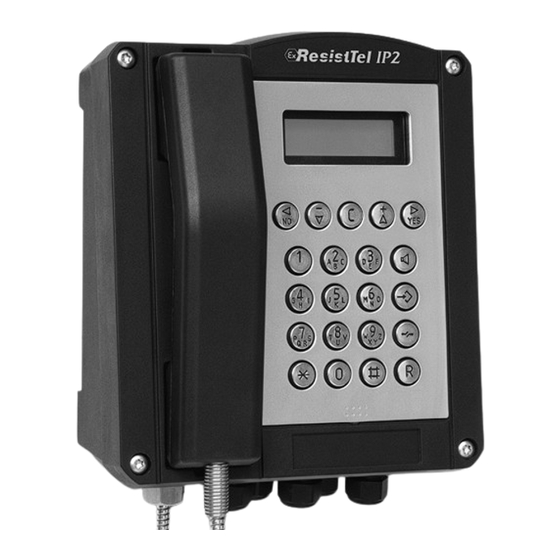
1 VoIP Telephone ResistTel IP2 / IP152 ExResistTel IP2 / IP154 1.1 Keypad Figure 1: Keypad of the VoIP-Telephone Short Manual ResistTel IP2 / IP152 Page 5 ExResistTel IP2 / IP154... -
Page 6: Keypad Description
1.2 Keypad Description Symbol Description and Key Functions The Loudspeaker key is used to control the hands free and listening mode. The Menu key is used to open the main menu or to save changes. The Disconnect key is used to terminate calls or any menu. The Enquiry key is used to enable the "Hold"... -
Page 7: Display
Symbol Description and Key Functions The headset key is used to make and to end a call in the headset mode. The phone ResistTel IP2 / IP152 has no single headset key. (long) To execute the headset key function the key has to be pressed long (longer than a second) and then the loudspeaker key to be pressed. - Page 8 Thorsten 06.04.10 14:40 0:12 Figure 3: Default Display (Busy State) Position Symbol Description Name (H.323 or SIP ID or nickname of the PBX configuration) Status line; provides information on the current status of the telephone by means of the following symbols. Date 06.04.10 Time...
-
Page 9: Menu And Listing Display
1.3.2 Menu and Listing Display The first six lines are used for the menu and listing display. The last line is used for display of menu level, display name, scroll information and type of entry. display name Figure 4: Menu and Listing Display of the VoIP Telephone Position Symbol Description... -
Page 10: Default Version One Lan Connection With A Cable Screw Cap
Accessories (optional): Headset with connection cable and attachment of the bracket. LAN connector from Phoenix Contact Type VS-08-RJ45-5-Q/IP67, order-no.: 1656990 LAN female connector for cable mounting from AMP NETCONNECT (TE Connectivity), order-no. 116604-2 Cable screw cap Sealing plugs 2 keys for TORX socket screws TX20, TX30 1.4.1 Default Version one LAN Connection with a Cable Screw •... -
Page 11: Version One Switch Lan Module With Two Lan Connections With Cable Screw Cap
1.4.3 Version Switch Module with two LAN Connections with Cable Screw Cap • 2 LAN connections internal • Housing with 1 cable screw caps and 2 bored holes with sealing plugs at the upper side. Box contents The scope of the delivery includes: Telephone Printed short manual Manual on CD... - Page 12 Guide the telephone wire through the cable screw cap (4) and place it on the terminals. Only wires having a sheath diameter of 5 to 9 mm should be used because otherwise the IP66 housing protection standard is not guaranteed. Prior to assembly, check cover seal for tightness.
- Page 13 The diameter of the drilled hole is dependent on the screw employed (screw diameter max. 8 mm) and the type of supporting base material (steel, wood, concrete, plasterboard etc.) and must be chosen accordingly. The distance in the width is 201 mm and the distance in the height is 195 mm. Figure 6: Set View Figure 7: Inside View of Telephone upper Part Short Manual...
- Page 14 Figure 8: Inside View of Telephone lower Part X1 X2 X3 X4 10 11 12 13 Figure 9: Connection Diagram with Single LAN Module Page 14 Short Manual ResistTel IP2 / IP152 ExResistTel IP2 / IP154...
- Page 15 X1 X2 X3 X4 LAN1 LAN2 10 11 12 13 Figure 10: Connection Diagram with Switch LAN Module Connector description empty Loudspeaker (left) Heater of the Display Illumination of the Display Display LAN Module Keypad Hookswitch (Reed Contact) RS232 Module (optional) Amplifier Module (optional) Handset Relay Module (optional)
-
Page 16: Lan-Connections
1.5.1 LAN-Connections 1.5.1.1 Default Version one LAN Connection with a Cable Screw Cap The telephone has in the default version one internal LAN-connection with a cable screw cap. For the connection a LAN cable must be pulled through the cable screw cap. -
Page 17: Version With Switch Lan Module With Two Lan Connections With Cable Screw Caps
1.5.1.3 Version with Switch LAN Module with two LAN Connections with Cable Screw Caps The telephone has in this version two internal LAN-connections with a cable screw cap. For the connection the LAN cable must be pulled through the cable screw cap. Inside the phone the female LAN connection from AMP NETCONNECT (TE Connectivity) has to be pressed on the cable (Refer to chapter 1.4 beginning on page 9). -
Page 18: External Power Supply Connection
1.5.2 External Power Supply Connection An external power supply can be adapted to the terminals 5 (+) and 6 (-). The voltage has to be: Without using the optional voltaic separated inputs: 15 V – 57 V DC, 12.95 W With using the optional voltaic separated inputs: 21,5 V –... -
Page 19: Other Terminals
Connector Description Cable to the main board (connection to plug in X12) 1 (relay 1) Idle contact relay 1 2 (relay 1) Base contact relay 1 3 (relay 1) Switching contact relay 1 1 (relay 2) Idle contact relay 2 2 (relay 2) Base contact relay 2 3 (relay 2) -
Page 20: Sling Holder
Caution While using the voltaic separated inputs with external power supply, the input voltage has to be 21.5 V – 57 V DC. 1.5.5 Sling Holder The holding strength for the handset is continuously adjustable. Loosen the screws (12) and move the stopping catches (13) (See Figure 6 on page 13). -
Page 21: Operating Manual
Operating Manual 2.1 Operating Basics The keys below the display ( ) of the VoIP telephone serve menu navigation and, for edit field input purposes, are assigned an additional function on top of their actual function, as explained below. Key assignment in menu: The function …... -
Page 22: Adjusting The Ringer Volume
You can increase the volume level by pressing the key You can reduce the volume level by pressing the key Martin vol. 06.04.10 14:40 0:22 Figure 12: Adjusting the Volume You control the volume of the active mode. • At the handset mode you control the volume of the speaker of the handset. •... -
Page 23: Do Not Disturb
2.1.3 Do not disturb You can turn off the do not disturb function of the VoIP telephone ResistTel IP2 / IP152 simply by pressing a key, for example if you do not wish to be disturbed during a meeting. 1. To activate the do not disturb function; press the key for about a second whilst in idle mode until the display appears in Figure 14. -
Page 24: Operating Modes
possible characters and special characters 1 + ( ) , - & @ # “ * ! $ % . / : ; < = > ? ' [ ] \ ^ _ `{ | } ~ £ § ¿ ÷ 2 a b c A B C ä... -
Page 25: Changeover From Handset Mode To Handset Mode With Open Listening
5. Headset mode with open listening At headset mode with open listening the call will be operated with the headset. The hands free speaker of the phone will be connected additionally. Persons present in the room can listen to the call. The already active operating mode will be displayed in the state line of the phone. -
Page 26: Changeover From Headset Mode To Headset Mode With Open Listening
2.2.7 Changeover from Headset Mode to Headset Mode with Open Listening To change from headset mode to headset mode with open listening, you have to press the loudspeaker key during a call. 2.2.8 Changeover from Headset Mode with Open Listening to Headset Mode To change from headset mode with open listening to headset mode, you have to press the loudspeaker key... -
Page 27: Terminating A Call
Answering or rejecting calls: If you would like to answer the call, you have different possibilities: • Lift the handset. • Press the loudspeaker key • Press the headset key (Key long (longer than a second) and then the loudspeaker key You will be connected to the caller. -
Page 28: Block Dialling
1. Respectively to the wanted calling mode: • Pick up the handset (handset mode). • Press the loudspeaker key (hands free mode). • Press the headset key (Key long (longer than a second) and then the loudspeaker key ) (headset mode). 2. -
Page 29: Menu Parameter Input Indirect Dialling
d. Press the key or key (short or long). With a configured headset you will reach the headset mode otherwise the hands free mode. e. Using the key (short or long) executes the selection immediately. Using the key , however, executes the selection only if the cursor is situated to the right of the last entered digit. -
Page 30: Dialling During Existing Connections
2.3.3.3 Dialling during existing Connections During existing connections all entered digits (0 – 9, *, #) are transmitted as DTMF signals. Using this DTMF procedure it is possible to access menu-controlled services (e. g. answering machines, voice boxes) directly via the telephone keypad. 2.3.4 Redialling Up to 100 of the last numbers dialled are saved automatically, together with the time... -
Page 31: Call Back
b. Press the loudspeaker key (hands free mode). c. Press the headset key (Key long (longer than a second) and then the loudspeaker key ) (headset mode). d. Press key (short or long) or the key . With a configured headset you will reach the headset mode otherwise the hands free mode. -
Page 32: Muting
a. Lift off the handset (handset mode). b. Press the loudspeaker key (hands free mode). c. Press the headset key (Key long (longer than a second) and then the loudspeaker key ) (headset mode). d. Press key (short or long) or the key . -
Page 33: Switching
1. Press the key (short) during a call. The call is put on hold. You hear a dial tone. The line on hold is displayed normally, the active line inversely (see Figure 21). 2. Dial the call number. A further connection is established. 3. -
Page 34: Transferring A Call
2.3.9 Transferring a Call You are making a call and would like to transfer it to another party. Torsten Peter Torsten Thomas 06.01.10 14:40 0:22 Figure 23: Transferring a Call 1. Press the key (short) during a call. The call is put on hold. You hear a dial tone. The line on hold is displayed normally and the active line inversely. -
Page 35: Transferring A Call Directly
2.3.10 Transferring a Call directly You are making a call and want to switch it to another connection. Torsten Peter Transfer Figure 24: Transferring a Call Directly 1. Press the key (long) during a call. 2. You will be left. The actual connection will not be displayed. 3. - Page 36 2. You can end the conference by pressing the key respective the key (short) followed by the key or twice the key (short). If you end the conference with pressing the key or the key (short) followed by the key , the call put on hold prior to the initiated conference is now on hold again and the previously active call is active once again.
-
Page 37: Technical Data Weatherproof Telephones
3 Technical Data weatherproof Telephones Hardware-ID Connection data Power supply Power over Ethernet refer to IEEE 802.3af or external power supply Voltage PoE 48V DC (Min. 44V, Max. 57V) Class 0 Voltage external power supply without 15 V – 57 V DC using the optional voltaic separated inputs Voltage external power supply for using... - Page 38 Environmental conditions Ambient operating temperature -40°C…+70°C Transport and storage temperature -40°C…+80°C Conformities Degree of protection IP66 acc. to IEC 60529 Degree of protection against external IK09 acc. to EN IEC 62262 mechanical impacts Declaration of Conformity Directive 1999/5/EU (R&TTE) Directive 2004/108/EG (EMC) Directive 2006/95/EG (low voltage) Restriction of Hazardous Substances Directive 2011/65/EG...
-
Page 39: Notes
4 Notes Short Manual ResistTel IP2 / IP152 Page 39 ExResistTel IP2 / IP154... - Page 40 Subject to alterations or errors FHF Funke + Huster Fernsig GmbH Gewerbeallee 15-19 · D-45478 Mülheim an der Ruhr Phone +49 / 208 / 82 68-0 · Fax +49 / 208 / 82 68-286 http://www.fhf.de · e-mail: info@fhf.de...
Need help?
Do you have a question about the ResistTel IP2/IP154 and is the answer not in the manual?
Questions and answers