Advertisement
Quick Links
Transient voltage surges are short-term deviations from a desired voltage level or signal that can occur at
any time. Such changes can result in an electronic device malfunction, or cause extensive damage. Also
termed "spikes" , these occurrences take place as a result of magnetic field/inductive coupling or whenever
the line current is interrupted. They can originate from either inside a facility, or derive from outside utility
lines. Sources within a facility involve loads that are switched, such as electric motors that are turned ON and
OFF. Outside transient influences involve utility grid switching.
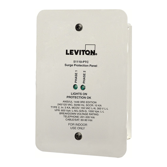
Leviton's 51110-PTC Residential Panel Surge Protection Device (SPD) is a high-performance Transient
Voltage Surge Suppressor. The Residential Panel SPD unit is designed for use on 120/240VAC at the
RESIDENTIAL PANEL SURGE
home's breaker panel. The SPD panel also houses protection circuits for telephone/modem line protection, a
CATV SPD circuit and a satellite circuit SPD. Diagnostics provide visual indicators for monitoring the
PROTECTION DEVICE (SPD)
120/240VAC protection status.
Cat. No. 51110-PTC
FOR INDOOR USE ONLY
• CULUS.
• Use with 120/240VAC single phase voltage systems.
• Hybrid component suppression design.
• TVSS protection on Line to Neutral, Line to Ground and Neutral to Ground.
• Common mode TVSS protection.
• Telco, SAT and CATV surge protection circuitry.
INSTALLATION INSTRUCTIONS
• Diagnostic monitoring of AC surge protection circuitry.
• Visual failure indicators for each L-N.
• Internal connection wiring within housing allows close installation to electrical distribution panels, thereby
• Convenient surface, stud, conduit or flush mounting.
DI-000-51110-00A
IMPORTANT SAFETY INSTRUCTIONS
SAVE THESE INSTRUCTIONS
LIMITED 10 YEAR WARRANTY AND EXCLUSIONS
Leviton warrants to the original consumer purchaser and not
WARNING:
for the benefit of anyone else that this product at the time of
its sale by Leviton is free of defects in materials and
WARNING:
workmanship under normal and proper use for ten years from
ELECTRICAL CODES AND REGULATIONS (INCLUDING NEC/CEC, AS APPLICABLE).
the purchase date. Leviton's only obligation is to correct such
defects by repair or replacement, at its option, if within such
WARNING:
ten year period the product is returned prepaid, with proof of
purchase date, and a description of the problem to Leviton
QUALIFIED ELECTRICIAN.
Manufacturing Co., Inc., Att: Quality Assurance
WARNING:
Department, 59-25 Little Neck Parkway, Little Neck, New
York 11362-2591. This warranty excludes and there is
AND TEST THAT THE POWER IS OFF BEFORE WIRING!
disclaimed liability for labor for removal of this product or
reinstallation. This warranty is void if this product is installed
WARNING:
improperly or in an improper environment, overloaded,
STRIKES IN CLOSE PROXIMITY TO THE PREMISES OR SUSTAINED OVERVOLTAGES.
misused, opened, abused, or altered in any manner, or is not
used under normal operating conditions or not in accordance
1. RESTORE POWER, if necessary.
with any labels or instructions. There are no other or implied
warranties of any kind, including merchantability and fitness
2. Verify that the electrical system in use is 120/240VAC single phase by the safe and proper use of AC
for a particular purpose, but if any implied warranty is required
by the applicable jurisdiction, the duration of any such implied
warranty, including merchantability and fitness for a particular
3. TURN OFF POWER.
purpose, is limited to ten years. Leviton is not liable for
incidental, indirect, special, or consequential damages,
4. Identify the device or load to be protected. Locate the SPD unit as close as possible to the electrical panel
including without limitation, damage to, or loss of use of, any
equipment, lost sales or profits or delay or failure to perform
this warranty obligation. The remedies provided herein are
the exclusive remedies under this warranty, whether based
on contract, tort or otherwise.
For Technical Assistance Call:
1-800-824-3005 (U.S.A. Only)
www.leviton.com
DI-000-51110-00A
DI-000-51110-00A
1
INTRODUCTION
DESCRIPTION
SPECIFICATIONS
providing a short suppression path, which optimises the clamping capability of the SPD.
TO INSTALL
THIS DEVICE MUST BE INSTALLED BY QUALIFIED PERSONNEL.
TO BE INSTALLED AND/OR USED IN ACCORDANCE WITH APPROPRIATE LOCAL
IF YOU ARE NOT SURE ABOUT ANY PART OF THESE INSTRUCTIONS, CONSULT A
TO AVOID FIRE, SHOCK, OR DEATH; TURN OFF POWER AT CIRCUIT BREAKER OR FUSE
THIS DEVICE IS NOT A LIGHTNING ARRESTOR. IT WILL NOT SURVIVE LIGHTNING
Voltage Measurement Equipment.
serving the loads to be protected, to minimize the effects of connection lead-length resistance and
inductance.
NOTE: Matching the TVSS model and electrical system line voltage is critical! Identify the system to be
protected by measuring L-N and L-L voltages. Use extreme caution while making voltage measurements!
If you are unsure of the type of electrical system in use, or the system voltage, stop and contact a qualified
electrician.
Confirm that the maximum measured voltage does not exceed the maximum continuous line voltage
specified for the 51110-PTC unit to be installed or damage will occur. Figure 1 illustrates the wiring
connection for the 51110-PTC.
5. Remove SPD cover to provide wiring access. Leads from the SPD must be connected to the power mains
through a 30 Amp (maximum) disconnect and fusing means. Either dedicated branch circuit breakers
(independent single-pole preferred), or a fused disconnect switch may be used. When the SPD device
shares a 2-pole ganged breaker, National Electric Code (NEC) and local requirements shall prevail.
NOTE: Sharing of breakers is not permitted by CEC in Canada.
NOTE: For best performance, installation wires should be twisted or bound together and as short as
possible. For optimal performance, connection wires longer than 12 inches should be avoided.
Leads from the SPD should be bundled together and secured with cable ties when possible. Conduit shall
be used where required by code. For best suppression, the cable and some cable ties may be cut down
from the supplied length to allow for a shorter installation path.
6. Mount the SPD unit securely. The 51110-PTC unit can be surface, stud or conduit mounted and has 2
removable mounting flanges on it's back. When the flanges are removed from the SPD unit back, they can
easily be side mounted by re-attaching them (using the same screws) to the top and bottom portion of
either side of the SPD (side holes provided). Side mounting flanges would be used to provide "stud
mounting" to a vertical support from the side and they would be used for flush mount applications. When
mounted in this manner, the Input and Output telephone wires would both need to be routed through the
same (unblocked) knockout hole and properly strain relieved. If flush mounting, install the flush mount
cover over the top of the standard cover and secure with the standard cover screws. Direct panel
mounting applications ("conduit mounted") should utilize a 3/4" conduit knockout hole with the dual
threaded nipple (provided).
7. When attaching the SPD connection leads to the power lines, first insert conduit fitting provided (or use
equivalent) into top knockout hole to protect insulation/wires. All four connection leads from inside the
SPD should be routed through the conduit fitting to the outside of the SPD. Then, the wires should be
routed to the circuit breaker terminals (refer to Figure 1) using the shortest path (cutting excess wire
length) to the power line. Use conduit, as required, by National Electric Code (NEC) and local
requirements. Avoid sharp bends. Lead wire insulation should not be cut or damaged.
8. Connection: Connect the Black wire (marked "Line 1") to one line, and the other Black wire (marked
"Line 2") to the other line. These Black wires may be connected to either L1 or L2 without regard to phase
angle.
9. The White wire should be connected to the system's Neutral bus.
10. The Green wire is attached internally to the 51110-PTC unit's metal enclosure. The Green wire must be
grounded to the electrical panel's ground bus.
11. Check that all connections are correct, tight, and secure.
FOR TELCO:
WARNING:
NEVER INSTALL TELEPHONE WIRING DURING A LIGHTNING STORM.
NOTES:
1. Disconnect telephone line at the network interface before installing the secondary protection.
2. This SPD unit is intended for Indoor Use Only.
INPUT WIRING:
1. Figure 2 shows telephone wiring using a maximum of 2 lines. Re-route telephone Service Untwisted
Shielded Pair (UTP) wires to directly enter the home and connect to the SPD unit "INPUT". Additional UTP
wire may be required.
2. Remove AC power to the SPD.
3. Remove the SPD cover to provide access to the telephone connection screw terminals.
4. The incoming telephone service wires are typically a UTP (or Category 5) wire composed of 2 or 4
multicolored pairs of insulated wire. Each telephone line requires one multicolored pair of wire. Remove
approximately 6 inches off the end of the outer jacket of the telephone wire and determine the number and
color of the pairs of wires inside.
NOTE: A maximum of two telephone lines (2 pairs of wires, refer to Figure 2) can be connected to the
SPD.
5. Insert bushings (provided) into the knockout hole to protect insulation/wires. Torque screws on strain relief
to 10 +/- 2 in.-lbs. If unit has been stud mounted, both Input and Output telephone lines must be routed
through the same (unblocked) knockout hole and properly strain relieved with the bushing provided.
6. Seperate the colored wire pairs and fasten to the screw terminal "INPUT" as shown in Figure 2.
7. Tighten screws using 3.5 in-lbs. of torque. Repeat procedure for up to 2 pairs of wires.
2/11/02, 3:29 PM
Advertisement

Subscribe to Our Youtube Channel
Related Manuals for Leviton 51110-PTC


Summary of Contents for Leviton 51110-PTC
- Page 1 Voltage Surge Suppressor. The Residential Panel SPD unit is designed for use on 120/240VAC at the 6. Mount the SPD unit securely. The 51110-PTC unit can be surface, stud or conduit mounted and has 2 RESIDENTIAL PANEL SURGE home's breaker panel.
- Page 2 Type F, Female to Female adapter may be installed for connection of the input cable to the output cable (thus bypassing the SPD unit) for that signal at the SPD unit, however surge protection will still be needed for the Figure 3 – 51110-PTC CATV & SAT CONNECTIONS equipment to be protected.
- Page 3 FOLD SCHEME 14.0¨ LEVITON INSTRUCTION SHEET/MANUAL SPECIFICATIONS Front Panel DI-000-51110-00A Black 8.5¨ Helvetica 50 Lb. offset Paper size: 14" X 8.5" Overall size: 2.8" X 4.25" Final fold size: DOCUMENTATION 02/11/02 Front Panel Front Panel Cat. No. Fold Line Cat. No.
Need help?
Do you have a question about the 51110-PTC and is the answer not in the manual?
Questions and answers