Advertisement
Quick Links
WARNING AND CAUTIONS:
•
TO BE INSTALLED AND/OR USED IN ACCORDANCE WITH APPROPRIATE
ELECTRICAL CODES AND REGULATIONS.
•
IF YOU ARE NOT SURE ABOUT ANY PART OF THESE INSTRUCTIONS, CONSULT
AN ELECTRICIAN.
•
THIS SPD IS A TYPE 1 DEVICE WHICH IS DESIGNED FOR USE WITH
LIGHTNING PROTECTION SYSTEMS (UL 96A).
•
THIS SPD MAY NOT SURVIVE SUSTAINED OVERVOLTAGES.
USE THIS DEVICE WITH COPPER OR COPPER CLAD WIRE ONLY.
•
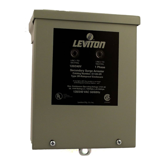
DESCRIPTION
Leviton's 51120-3R Outdoor SPD Panel Protection Systems is a high-performance Surge
Protective Device. This unit is designed for use at the service entrance, utility kW-h meter
or outdoor equipment applications. Diagnostics provide visual monitoring of power status.
DESIGN FEATURES
•
NEMA 3R Outdoor rated enclosure.
•
Easy to install housing with pre-punched knockouts in enclosure.
•
Easily removeable DIN-rail mounted surge protection module.
•
ETL listed Type 1 device.
•
IEEE C62.41-1991 category C3 and C62.11 Metal Oxide Surge Arrester combination
wave suppressor.
•
40mm TPMOV fused SPD circuitry for both Line 1 and 2 to Neutral and Line-to-Line
through the Neutral path.
•
Illuminated Green LED indicates surge protection is stable on Lines 1 or 2.
TO INSTALL
WARNING:
TO AVOID FIRE, SHOCK, OR DEATH; TURN OFF POWER AT CIRCUIT
BREAKER OR FUSE AND TEST THAT THE POWER IS OFF BEFORE WIRING!
1.
IMPORTANT: First mount the enclosure and connect the conduit to the service panel
to be protected, as per the NEC or CEC.
CAUTION: DO NOT lengthen the module leads. This will result in reduced
performance.
2.
Identify the electrical system in use, 120/240V system (L-L/L-N).
Confirm that the maximum measured voltage matches the AC RMS voltage rating
specified for the units to be installed or damage will occur.Each Line to Neutral shall
be 120V RMS nominal.
NOTE: The total connection length between the branch power lines and SPD
device should be as short as possible. The cable jacket keeps wires together
for best suppression.
3.
Identify the device or load to be protected. Locate the SPD unit as close as possible
to the electrical panel serving the loads to be protected, to minimize the effects of
connection lead-length resistance and inductance.
4.
The SPD provides prepunched knockouts on the bottom of the unit. Select from the
1/2" or 3/4" for your application. Conduit should be installed with lock nut and bushing.
Lock nut should be adjusted so that bushing secures properly.
FIG. 2
AS SHORT AS POSSIBLE
See TO INSTALL
L1 (Black)
FIG. 4
Surge Protective Device (SPD)
To Ground Block
(not shown)
L2 (Red)
N (White)
G (Green)
Ground
Ground Connection
Wire Well Opening
Ground Pigtail
Cat. No. 51120-3R
INSTALLATION
5.
Install the module as follows (refer to Figs. 2, 3, and 4): Engage the module
mounting clip on the left side of the rail. Press right side down until locked. Slide
module down until it contacts ground block to line up LEDs with cover lenses. Connect
the pigtail ground wire to a terminal on the ground block which is mounted on the rail
(refer to Fig. 4).
Normal ground connection is to the right ground clamp on the ground block. Remove
1/2" insulation of the ground wire and insert into wire well. Tighten ground clamp
screw to 15±2 in./lb. torque. DO NOT turn the center screw on the ground block as the
ground block may move on the rail and the LEDs on the module may not line up with
the cover lenses.
Connect module wires to the service panel according to Fig. 1.
6.
When attaching the SPD connection leads to the power lines, all connection leads
from the SPD unit should be cut to a length which provides the shortest path to the
power line. Avoid sharp bends. Lead wire insulation should not be cut or damaged.
7.
With power still OFF, mount the cover and tighten the cover screws to 20-25 in./lb.
torque to ensure ground continuity.
8.
Activate the system by turning power ON. The Green indicator lights should be ON. If
the indicator lights are not ON, consult an electrician.
9.
Failure indication may occur due to excessive transients, a direct lightning strike or
steady-state overvoltages. If any of these events occur, one or more Green LEDs may
be OFF. When power is applied to the SPD unit and one or more Green LEDs are
OFF, the unit has failed and must be replaced.
To remove module (refer to Fig. 3):
Lift the release lever while lifting up the right side of the module and swing the module off
the rail.
FIG. 1 - 120/240V AC SINGLE PHASE
FIG. 3
Mounting
Clip
LIMITED LIFETIME WARRANTY AND EXCLUSIONS
Leviton warrants to the original consumer purchaser and not for the benefit of anyone else that
this product at the time of its sale by Leviton is free of defects in materials and workmanship
under normal and proper use during the lifetime of the product. Leviton's only obligation is to
correct such defects by repair or replacement, at its option, if the product is returned prepaid,
with proof of purchase date, and a description of the problem to Leviton Manufacturing Co.,
Inc., Att: Quality Assurance Department, 201 North Service Road, Melville, N.Y. 11747.
This warranty excludes and there is disclaimed liability for labor for removal of this product
or reinstallation. This warranty is void if this product is installed improperly or in an improper
environment, overloaded, misused, opened, abused, or altered in any manner, or is not
used under normal operating conditions or not in accordance with any labels or instructions.
There are no other or implied warranties of any kind, including merchantability and fitness
for a particular purpose. Leviton is not liable for incidental, indirect, special, or consequential
damages, including without limitation, damage to, or loss of use of, any equipment, lost sales
or profits or delay or failure to perform this warranty obligation. The remedies provided herein
are the exclusive remedies under this warranty, whether based on contract, tort or otherwise.
For Technical Assistance Call: 1-800-824-3005 (U.S.A. Only) www.leviton.com
Line 1
Red
Line 2
Black
Neutral
White
Green
Ground
Mounting Rail
© 2010 Leviton Mfg. Co., Inc.
DI-140-51120-00A
ENGLISH
Cat. No. 51120
Release
Lever
Advertisement

Subscribe to Our Youtube Channel
Related Manuals for Leviton 51120-3R


Summary of Contents for Leviton 51120-3R
- Page 1 Leviton warrants to the original consumer purchaser and not for the benefit of anyone else that this product at the time of its sale by Leviton is free of defects in materials and workmanship under normal and proper use during the lifetime of the product. Leviton’s only obligation is to correct such defects by repair or replacement, at its option, if the product is returned prepaid, with proof of purchase date, and a description of the problem to Leviton Manufacturing Co.,...
- Page 2 COMMENTS : The information in this document is the exclusive PROPRIETARY property of LEVITON MANUFACTURING COMPANY, INC. It is disclosed with the understanding that acceptance or review by the recipient constitues an undertaking by the recipient. (1) to hold this information in strict ©...
Need help?
Do you have a question about the 51120-3R and is the answer not in the manual?
Questions and answers