Table of Contents
Advertisement
Quick Links
Advertisement
Table of Contents
Troubleshooting

Subscribe to Our Youtube Channel
Related Manuals for IKUSI OP-131Tx Series


Summary of Contents for IKUSI OP-131Tx Series
- Page 1 OP-131Tx 1310nm Optical Transmitter 45 ~ 2600MHz User Manual...
-
Page 2: Table Of Contents
..........................18 ROUBLESHOOTING 6.3 D ............................19 ISCLAIMER 7.0 G ......................19 UARANTEE AND EPAIR ITEMS OP-131Tx_V2 User Manual.docx Page 2 of 19 30-Aug-2018 © 2018 IKUSI ANZ Pty Ltd - All rights reserved - Reproduction without consent is prohibited... -
Page 3: Product Summary
Analog TV, Digital TV (DVB-C, DVB-T) and Satellite TV in one optical fiber. Applicable receivers: OP-1Rx OP-131Tx_V2 User Manual.docx Page 3 of 19 30-Aug-2018 © 2018 IKUSI ANZ Pty Ltd - All rights reserved - Reproduction without consent is prohibited... - Page 4 80dBµV AGC OMI=3.8% C/CSO ≥58 Input Impedance Ω RF Connector F type Male/Female Specified by the user OP-131Tx_V2 User Manual.docx Page 4 of 19 30-Aug-2018 © 2018 IKUSI ANZ Pty Ltd - All rights reserved - Reproduction without consent is prohibited...
-
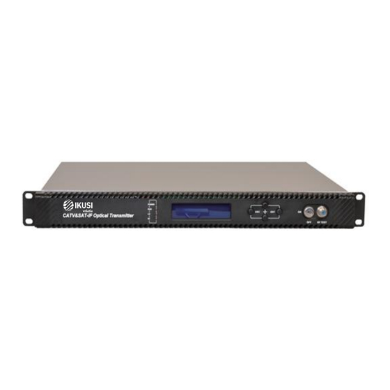
Page 5: Panel Interface And Menu System Description
No input or exceed the LED flash red normal range RF input indicator Normal LED green OP-131Tx_V2 User Manual.docx Page 5 of 19 30-Aug-2018 © 2018 IKUSI ANZ Pty Ltd - All rights reserved - Reproduction without consent is prohibited... -
Page 6: Rear Panel
Menu 1: Display parameters 2.Set Parameters Menu 2: Set parameters 3.Alarm Status Menu 3: Alarm status OP-131Tx_V2 User Manual.docx Page 6 of 19 30-Aug-2018 © 2018 IKUSI ANZ Pty Ltd - All rights reserved - Reproduction without consent is prohibited... -
Page 7: Display Menu
-5V monitor voltage Software Ver Software version number +12V +12V monitor voltage +18V +18V monitor voltage OP-131Tx_V2 User Manual.docx Page 7 of 19 30-Aug-2018 © 2018 IKUSI ANZ Pty Ltd - All rights reserved - Reproduction without consent is prohibited... -
Page 8: Setup Menu
-5V voltage alarm +12V Alarm: +12V voltage alarm +18V Alarm: +18V voltage alarm +24V Alarm +24V voltage alarm OP-131Tx_V2 User Manual.docx Page 8 of 19 30-Aug-2018 © 2018 IKUSI ANZ Pty Ltd - All rights reserved - Reproduction without consent is prohibited... -
Page 9: Installing The Op-131Tx Optical Transmitter
The plug-socket combination must be accessible at all Warning times, because it serves as the main disconnecting device. OP-131Tx_V2 User Manual.docx Page 9 of 19 30-Aug-2018 © 2018 IKUSI ANZ Pty Ltd - All rights reserved - Reproduction without consent is prohibited... -
Page 10: Mounting The Op-131Tx
(SNR) performance. 4. Note the key characteristics of the mating connectors and align them accordingly. OP-131Tx_V2 User Manual.docx Page 10 of 19 30-Aug-2018 © 2018 IKUSI ANZ Pty Ltd - All rights reserved - Reproduction without consent is prohibited... -
Page 11: Connecting The Ethernet Cable
The serial communication uses the standard NRZ form, 1 starts bit, 8 data bits, 1 stop bit and the baud rate is 38400. OP-131Tx_V2 User Manual.docx Page 11 of 19 30-Aug-2018 © 2018 IKUSI ANZ Pty Ltd - All rights reserved - Reproduction without consent is prohibited... -
Page 12: Set Up The Hyper Terminal
“OK” button, you have set up the Windows serial port Hyper Terminal. OP-131Tx_V2 User Manual.docx Page 12 of 19 30-Aug-2018 © 2018 IKUSI ANZ Pty Ltd - All rights reserved - Reproduction without consent is prohibited... -
Page 13: Operating Parameter Configuration
You can input your command in this page, and then configure the operating parameter of the application program. OP-131Tx_V2 User Manual.docx Page 13 of 19 30-Aug-2018 © 2018 IKUSI ANZ Pty Ltd - All rights reserved - Reproduction without consent is prohibited... - Page 14 You can also use the “help” command to show help information of other commands, such as “help ethcfg”,ethcfg’s help information appears as follows: OP-131Tx_V2 User Manual.docx Page 14 of 19 30-Aug-2018 © 2018 IKUSI ANZ Pty Ltd - All rights reserved - Reproduction without consent is prohibited...
- Page 15 This command is used to set company logo and equipment model. Exit This command is used to logout. OP-131Tx_V2 User Manual.docx Page 15 of 19 30-Aug-2018 © 2018 IKUSI ANZ Pty Ltd - All rights reserved - Reproduction without consent is prohibited...
-
Page 16: Remote Monitoring: Snmp
The configuration of initial state can be achieved through the RS-232 interface or the front panel keys. Other configurations see our <Network Management Instructions>. OP-131Tx_V2 User Manual.docx Page 16 of 19 30-Aug-2018 © 2018 IKUSI ANZ Pty Ltd - All rights reserved - Reproduction without consent is prohibited... -
Page 17: Maintenance And Troubleshooting
4. In one continuous motion, pull the connector from the wet part of the paper to the dry part. OP-131Tx_V2 User Manual.docx Page 17 of 19 30-Aug-2018 © 2018 IKUSI ANZ Pty Ltd - All rights reserved - Reproduction without consent is prohibited... -
Page 18: Troubleshooting
Status HIGH The laser is off problem, contact Customer (LOW) Service. OP-131Tx_V2 User Manual.docx Page 18 of 19 30-Aug-2018 © 2018 IKUSI ANZ Pty Ltd - All rights reserved - Reproduction without consent is prohibited... -
Page 19: Disclaimer
Original Packaging and must be in Good Saleable Condition. Goods not meeting this condition will be rejected for credit. OP-131Tx_V2 User Manual.docx Page 19 of 19 30-Aug-2018 © 2018 IKUSI ANZ Pty Ltd - All rights reserved - Reproduction without consent is prohibited...
Need help?
Do you have a question about the OP-131Tx Series and is the answer not in the manual?
Questions and answers