IKUSI TM70 Series Operation & Installation Manual
Pushbutton transmitters
Hide thumbs
Also See for TM70 Series:
- Operation & installation manual (19 pages) ,
- Service manual (28 pages)
Table of Contents
Advertisement
Available languages
Available languages
Advertisement
Table of Contents

Subscribe to Our Youtube Channel
Related Manuals for IKUSI TM70 Series


Summary of Contents for IKUSI TM70 Series
- Page 1 MANUAL DE INSTALACIÓN Y DE UTILIZACIÓN TM70 TRANSMISOR BOTONERA MODELOS T70/1 & T70/2 (DOS PASOS) MODELOS T70/1 & T70/2 (PROPORCIONAL) TM70Be V4.1 (03/12) 1121174.pdf IKUSI se reserva el derecho de modificar esta información sin previo aviso.
-
Page 2: Table Of Contents
INTRODUCCION 10.2.- ......................32 SISTEMAS CON DOS TRANSMISORES 11.-OPCION LIMITADOR DE ALCANCE LA70 / LA70M ................33 11.1.1- ........................34 DESCRIPCION DEL SISTEMA 11.1.2- ..........................34 SENSOR INFRARROJO TM70Be V4.1 (03/12) 1121174.pdf IKUSI se reserva el derecho de modificar esta información sin previo aviso. - Page 3 OBSERVACIONES PARA EL CABLEADO INTERNO 22.- OPCION SELECTOR ROTATIVO BINARIO ....................84 22.1- ........................85 CARACTERISTICAS PRINCIPALES 22.2- 70/1 T70/2..........86 MODO DE FUNCIONAMIENTO CON TRANSMISORES MODELOS T TM70Be V4.1 (03/12) 1121174.pdf IKUSI se reserva el derecho de modificar esta información sin previo aviso.
- Page 4 FUNCIONAMIENTO DE LA ORDEN PRESENTE EN TRANSMISORES T PROPORCIONALES 25.- OPCIONES IN/OUT 0-4/20 A ........................98 25.1- 0-4/20 A ..........................99 OPCION IN 25.2- 0-4/20 A..........................100 OPCION OUT TM70Be V4.1 (03/12) 1121174.pdf IKUSI se reserva el derecho de modificar esta información sin previo aviso.
-
Page 5: Declaracion De Conformidad (Banda Ism 870Mhz)
Mikel Castilla Albisu EN 60529: 2001 Director de Calidad / Quality Director EN 13557: 2004 + A1:2006 01/09/2011 EN 13849: 2006 prEN 280: 2009 TM70Be V4.1 (03/12) 1121174.pdf IKUSI se reserva el derecho de modificar esta información sin previo aviso. -
Page 6: Declaracion De Conformidad (Banda Ism 433Mhz)
EN 60204-32: 2001 Director de Calidad / Quality Director EN 60529: 2001 01/09/2011 EN 13557: 2004 + A1:2006 EN 13849: 2006 prEN 280: 2009 TM70Be V4.1 (03/12) 1121174.pdf IKUSI se reserva el derecho de modificar esta información sin previo aviso. -
Page 7: Descripción Del Sistema
Capacidad 750 mAh NiMH Temperatura de carga 0º a 45ºC Temperatura de descarga -20º a 50ºC Autonomía 10 h (utilización al 50%) Peso 70,3g TM70Be V4.1 (03/12) 1121174.pdf IKUSI se reserva el derecho de modificar esta información sin previo aviso. -
Page 8: Instrucciones De Seguridad
No provocar golpes sobre el aparato. No utilizar el aparato si éste presenta síntomas de fallo. Los cambios o las modificaciones no expresamente aprobados por IKUSI podrían anular la autoridad del usuario para utilizar este equipo. El equipo puede funcionar en una altura superior a 1000 metros sobre el nivel del mar. -
Page 9: Recomendaciones Fcc
(2) l'utilisateur de l'appareil doit accepter tout brouillage radioélectrique subi, même si le brouillage est susceptible d'en compromettre le fonctionnement. TM70Be V4.1 (03/12) 1121174.pdf IKUSI se reserva el derecho de modificar esta información sin previo aviso. -
Page 10: Instalación
Utilizar únicamente baterías del fabricante Las baterías agotadas deben ser recicladas de acuerdo con las normas locales Las baterías ATEX – IKUSI (BT06K-ATEX y BT20K-ATEX), sólo pueden ser cargadas en cargadores BC70K o CB70. TM70Be V4.1 (03/12) 1121174.pdf... -
Page 11: Receptor
Caso de no ser posible una ubicación adecuada del receptor que permita la utilización de su antena interna, utilizar el kit prolongador con antena exterior. TM70Be V4.1 (03/12) 1121174.pdf IKUSI se reserva el derecho de modificar esta información sin previo aviso. - Page 12 No olvide conectar el cable de tierra. Utilice cables ignífugos para el conexionado. Seleccione la tensión adecuada en el receptor, (230, 115 ó 48 Vca – 12 o 24 Vcc). TM70Be V4.1 (03/12) 1121174.pdf IKUSI se reserva el derecho de modificar esta información sin previo aviso.
-
Page 13: Puesta En Marcha
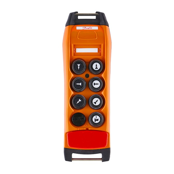
5.- Pulsador de marcha. 6.- Pulsador de paro. 7.- Opción: Limitador de área de trabajo. Figura 2. Elementos de señalización y control del transmisor TM70Be V4.1 (03/12) 1121174.pdf IKUSI se reserva el derecho de modificar esta información sin previo aviso. - Page 14 NOTA IMPORTANTE: IKUSI NO se responsabiliza de una instalación incorrecta, interferencias producidas por colisión de frecuencias, ni de la gestión de las frecuencias de trabajo en instalaciones fijas, donde varios telemandos vía radio, comparten o pueden compartir, una misma zona o área de trabajo.
-
Page 15: Utilización
Para desconectar el transmisor, presionar el pulsador de paro o girar la llave de contacto. Recuerde que va a telemandar una máquina móvil. Respete escrupulosamente las instrucciones de seguridad descritas en el capítulo 3 de este manual. TM70Be V4.1 (03/12) 1121174.pdf IKUSI se reserva el derecho de modificar esta información sin previo aviso. -
Page 16: Mantenimiento
7.- MANTENIMIENTO 7.1.- GARANTÍA IKUSI garantiza los telemandos TM70 por un período de 1 año desde su expedición. Esta garantía cubre la reparación y reposición de elementos defectuosos en nuestros Servicios de Asistencia Técnica, para lo que será preciso disponer tanto del transmisor como del receptor. -
Page 17: Localizacion De Averias
Código ID OK No reconoce el código ID ORDER Alguna maniobra Ninguna maniobra digital digital activada activada RELAY Relés de STOP Relés de STOP activados desactivados TM70Be V4.1 (03/12) 1121174.pdf IKUSI se reserva el derecho de modificar esta información sin previo aviso. - Page 18 "Error LAL not Problemas al abrir el limitador de alcance open" "Error Read LAL No se pueden leer datos del limitador de alcance err" TM70Be V4.1 (03/12) 1121174.pdf IKUSI se reserva el derecho de modificar esta información sin previo aviso.
-
Page 19: Anexo A.- Programación Del Emisor De Reserva
EP70, (en caso de que el emisor disponga de LCD, éste indicará “Writting...”). A continuación, pulsar STOP. El emisor de reserva se encuentra ahora programado. TM70Be V4.1 (03/12) 1121174.pdf IKUSI se reserva el derecho de modificar esta información sin previo aviso. -
Page 20: Anexo B.- Edición De La Identificación De La Máquina En Display Lcd
Pulsar START para memorizar el texto editado. En la pantalla aparecerá “SAVED” durante 2 segundos. Una vez se ha editado el último carácter, se abandona el modo EDICIÓN pulsando STOP. TM70Be V4.1 (03/12) 1121174.pdf IKUSI se reserva el derecho de modificar esta información sin previo aviso. -
Page 21: Cambio De Frecuencia
8.- CAMBIO DE FRECUENCIA CAMBIO DE FRECUENCIA TM70 TM70Be V4.1 (03/12) 1121174.pdf IKUSI se reserva el derecho de modificar esta información sin previo aviso. -
Page 22: Descripción Del Sistema
las decenas por pulsos de color verde, las unidades por pulsos de color rojo. TM70Be V4.1 (03/12) 1121174.pdf IKUSI se reserva el derecho de modificar esta información sin previo aviso. -
Page 23: Cambio Del Canal De Trabajo
PULSADOR DE MARCHA: el avance del CT se consigue pulsando el botón de Marcha durante 2 segundos. El avance del CT se señaliza mediante un pulso rojo. TM70Be V4.1 (03/12) 1121174.pdf IKUSI se reserva el derecho de modificar esta información sin previo aviso. -
Page 24: 434,790 Mh Z
NOTA: La potencia RF se ajusta automáticamente a los niveles permitidos como sigue: Canales 1 a 40: 1 mW Canales 41 a 70: 10 mW TM70Be V4.1 (03/12) 1121174.pdf IKUSI se reserva el derecho de modificar esta información sin previo aviso. -
Page 25: Anexo B - Tabla De Frecuencias Banda 869,70625 - 869,90 Mh Z
ANEXO B: Banda 869.70625 – 869.98125 MHz CANAL 869,70625 869,73125 869,75625 869,78125 869,80625 869,83125 869,85625 869,88125 869,90625 869,93125 869,95625 869,98125 TM70Be V4.1 (03/12) 1121174.pdf IKUSI se reserva el derecho de modificar esta información sin previo aviso. -
Page 26: 915,875 Mh Z
914,725 915,600 914,750 915,625 914,775 915,650 914,800 915,675 914,825 915,700 914,850 915,725 914,875 915,750 914,900 915,775 914,925 915,800 914,950 915,825 914,975 915,850 915,000 915,875 TM70Be V4.1 (03/12) 1121174.pdf IKUSI se reserva el derecho de modificar esta información sin previo aviso. -
Page 27: Interfaz Canopen
9.- INTERFAZ CAN OPEN INTERFAZ CANopen TM70 TM70Be V4.1 (03/12) 1121174.pdf IKUSI se reserva el derecho de modificar esta información sin previo aviso. -
Page 28: Introduccion
9.2.- CONEXIÓN DEL BUS CAN Para conectar el bus CAN a la tarjeta LR72, ésta dispone de una borna enchufable (P4) de 5 polos: TM70Be V4.1 (03/12) 1121174.pdf IKUSI se reserva el derecho de modificar esta información sin previo aviso. -
Page 29: Diccionario De Datos
1015: INHIBIT TIME EMERGENCY 1017: PRODUCER HEARTBEAT TIME 1018: IDENTITY OBJECT 1018.0: number of entries 1018.1: Vendor ID 1018.2: Product Code 1018.3: Revision Number 1018.4: Serial number TM70Be V4.1 (03/12) 1121174.pdf IKUSI se reserva el derecho de modificar esta información sin previo aviso. -
Page 30: Pdo
Encendido permanentemente en estado operacional Un destello por segundo en estado de parada CAN-ERR (rojo): indica error si encendido; en condiciones normales debe estar apagado. TM70Be V4.1 (03/12) 1121174.pdf IKUSI se reserva el derecho de modificar esta información sin previo aviso. -
Page 31: Receptores Can Tm70
Temperatura de almacenamiento –largos periodos- -25ºC / +55ºC (-13ºF / 131ºF) Transmisores soportados en la gama TM70 T70/1/2; T70/3/4; T70/5/6; T70/7/8 Equipos completos disponibles REf. 3302XXX TM70/X CAN-C1-915 TM70Be V4.1 (03/12) 1121174.pdf IKUSI se reserva el derecho de modificar esta información sin previo aviso. - Page 32 -25ºC / +75ºC (-13ºF / 167ºF) Temperatura de almacenamiento –largos periodos- -25ºC / +55ºC (-13ºF / 131ºF) Transmisores soportados en la gama TM70 T70/1/2; T70/3/4; T70/5/6; T70/7/8;i-KONTROL TM70Be V4.1 (03/12) 1121174.pdf IKUSI se reserva el derecho de modificar esta información sin previo aviso.
- Page 33 Existe la opción de suministro de un “kit de fijación rápida” compuesto por un juego de 4 imanes y 4 amortiguadores, Ref. IKUSI 3302620 TM70Be V4.1 (03/12) 1121174.pdf IKUSI se reserva el derecho de modificar esta información sin previo aviso.
- Page 34 Encendido permanentemente en estado operacional los LEDS Un destello por segundo en estado de parada CAN-ERR (rojo): indica error si encendido; en condiciones normales debe estar apagado. TM70Be V4.1 (03/12) 1121174.pdf IKUSI se reserva el derecho de modificar esta información sin previo aviso.
-
Page 35: Modo De Funcionamiento "First Come - First Served
10.- MODO DE FUNCIONAMIENTO “FIRST COME – FIRST SERVED” “FIRST COME – FIRST SERVED” MODO DE FUNCIONAMIENTO TM70 TM70Be V4.1 (03/12) 1121174.pdf IKUSI se reserva el derecho de modificar esta información sin previo aviso. -
Page 36: Introduccion
ID y canales de radio, buscando una trama con la orden de marcha pulsada. El modo de operación First come – First served permite tener hasta 32 transmisores diferentes gobernando un único receptor. TM70Be V4.1 (03/12) 1121174.pdf IKUSI se reserva el derecho de modificar esta información sin previo aviso. -
Page 37: Opcion Limitador De Alcance La70 / La70M
11.- OPCION LIMITADOR DE ALCANCE LA70 / LA70M OPCION LIMITADOR DE ALCANCE LA70 / LA70M TM70 TM70Be V4.1 (03/12) 1121174.pdf IKUSI se reserva el derecho de modificar esta información sin previo aviso. -
Page 38: 1- Descripcion Del Sistema
Si esta situación se mantiene durante 4 segundos, se retiran todas las órdenes activas, aunque manteniendo TM70Be V4.1 (03/12) 1121174.pdf IKUSI se reserva el derecho de modificar esta información sin previo aviso. -
Page 39: Tm70Be V4.1 (03/12) 1121174.Pdf
El haz de emisión no es simétrico, sino que tiene un ángulo mayor en sentido de avance longitudinal del puente que en el sentido transversal del carro. h (m) D (m) ± 63º d (m) ± 40º TM70Be V4.1 (03/12) 1121174.pdf IKUSI se reserva el derecho de modificar esta información sin previo aviso. -
Page 40: Instalacion Y Conexionado La70
Colocar el jumper de selección de modo como maestro. Seleccionar el código programado en la memoria EEPROM del emisor. TM70Be V4.1 (03/12) 1121174.pdf IKUSI se reserva el derecho de modificar esta información sin previo aviso. -
Page 41: Caracteristicas Tecnicas La 70
11.2.3 - CARACTERÍSTICAS TÉCNICAS LA70 Emisor Infrarrojo Alimentación 48, 115, 230 Vca ± 10%; 50/60 Hz Temperatura de trabajo -20 a +65ºC Protección IP55 TM70Be V4.1 (03/12) 1121174.pdf IKUSI se reserva el derecho de modificar esta información sin previo aviso. -
Page 42: Emisor Infrarrojo La70M
HARDWARE OK –parpadeo en verde- / ERROR –apagado- Montaje rápido Mediante imanes (configuración estándar) Dimensiones externas 80 mm x 160 mm x 65 mm (Largo x Ancho x Alto) TM70Be V4.1 (03/12) 1121174.pdf IKUSI se reserva el derecho de modificar esta información sin previo aviso. - Page 43 Area de cobertura circular de la emisión infrarroja (D=d) TODOS los LEDs en paralelo. h (m) D (m) ± 0º d (m) ±0º 20-35 TM70Be V4.1 (03/12) 1121174.pdf IKUSI se reserva el derecho de modificar esta información sin previo aviso.
- Page 44 I14: Selección compatibilidad TM60 o TM70 I2: funcionalidad NO operativa (Posición “Normal” por defecto) LED’s IR SELECTOR CÓDIGO Normal Expandido CONECTORES SELECTOR ID J-TAG LA60/70 I-14 LA60 LA70 TM70Be V4.1 (03/12) 1121174.pdf IKUSI se reserva el derecho de modificar esta información sin previo aviso.
-
Page 45: 2- Instalacion Y Conexionado La 70 M
último módulo de expansión (si la instalación lleva módulos de expansión) ALIMENTACION AC/DC LA70M EX LA70M AC / LA70M DC LA70M EX TAPON ID=3 (*) Número máximo de expansiones (por módulo Maestro) = 2 TM70Be V4.1 (03/12) 1121174.pdf IKUSI se reserva el derecho de modificar esta información sin previo aviso. -
Page 46: Modo De Funcionamiento "Pitch & Catch
12.- MODO DE FUNCIONAMIENTO “PITCH & CATCH” “PITCH & CATCH” MODO DE FUNCIONAMIENTO TM70 TM70Be V4.1 (03/12) 1121174.pdf IKUSI se reserva el derecho de modificar esta información sin previo aviso. -
Page 47: Introduccion
STOP o se produce una pérdida de enlace. 12.2- SISTEMAS CON DOS EMISORES RECEPTOR 1 TRANSMISOR 1 TRANSMISOR 2 TM70Be V4.1 (03/12) 1121174.pdf IKUSI se reserva el derecho de modificar esta información sin previo aviso. - Page 48 Cuando la operación Pitch & Catch ha finalizado, el primer emisor que pulse MARCHA se hará cargo del gobierno de la grúa. Este modo de funcionamiento se personaliza en la EEPROM del equipo y debe ser grabado en Fábrica. TM70Be V4.1 (03/12) 1121174.pdf IKUSI se reserva el derecho de modificar esta información sin previo aviso.
-
Page 49: Sistemas Multigrua: Modo De Funcionamiento En Tandem
13.- SISTEMAS MULTIGRUA: MODO DE FUNCIONAMIENTO EN TANDEM SISTEMAS MULTIGRUA TANDEM TM70 MODO DE FUNCIONAMIENTO TM70Be V4.1 (03/12) 1121174.pdf IKUSI se reserva el derecho de modificar esta información sin previo aviso. -
Page 50: Introduccion
La configuración por defecto de las frecuencias utilizadas en los equipos tándem suministrados desde fabrica son F1= CB y F2= CB+4. Por defecto CB = CT. TM70Be V4.1 (03/12) 1121174.pdf IKUSI se reserva el derecho de modificar esta información sin previo aviso. -
Page 51: Sistemas Con Un Emisor Maestro
MAESTRO y pulsar MARCHA. De este modo, el RECEPTOR 2 queda de nuevo disponible para ser utilizado por el emisor ESCLAVO, y el emisor MAESTRO pasa a controlar únicamente el RECEPTOR 1. TM70Be V4.1 (03/12) 1121174.pdf IKUSI se reserva el derecho de modificar esta información sin previo aviso. -
Page 52: Sistema Con Dos Emisores Maestros
Cuando se trata de emisores de tipo pupitre, la función “L” se incluye en un selector rotativo de cuatro posiciones “L / 1 / 1+2 / 2”. Por lo demás, la operatividad es la misma en ambos casos. TM70Be V4.1 (03/12) 1121174.pdf IKUSI se reserva el derecho de modificar esta información sin previo aviso. -
Page 53: Retorno Analogico / Opcion 0-10V / Calibracion
14.- RETORNO ANALOGICO / OPCION IN 0-10V: CALIBRACION RETORNO ANALOGICO OPCION IN 0-10v CALIBRACION TM70 TM70Be V4.1 (03/12) 1121174.pdf IKUSI se reserva el derecho de modificar esta información sin previo aviso. -
Page 54: Introduccion
6. Pulsar el pulsador 4 para entrar en el MENU. 7. Para desplazarse por el Menú, utilizar los pulsadores 1 y 2 hasta llegar al menú CALIBRATION. 8. Pulsar 4 TM70Be V4.1 (03/12) 1121174.pdf IKUSI se reserva el derecho de modificar esta información sin previo aviso. - Page 55 Pulsar el pulsador 1 para editar las UNIDADES. Validar las unidades pulsando START. Apagar el equipo. El equipo ya está preparado para funcionar normalmente. TM70Be V4.1 (03/12) 1121174.pdf IKUSI se reserva el derecho de modificar esta información sin previo aviso.
-
Page 56: Montaje Expansion In0-10V Con Lr71/72
14.3 - MONTAJE EXPANSION IN0-10V CON LR71/72 IN0-10V (Ref. 2303755) Cod-2303755 Cod-1131026(x4) Cod-1135024(x2) TM70Be V4.1 (03/12) 1121174.pdf IKUSI se reserva el derecho de modificar esta información sin previo aviso. -
Page 57: Opcion In0450P
15.- OPCION IN0450P OPCION IN0450P TM70 TM70Be V4.1 (03/12) 1121174.pdf IKUSI se reserva el derecho de modificar esta información sin previo aviso. -
Page 58: Introduccion Y Descripcion Funcional
Aislada galvánicamente de la lógica. Rango de temperatura: –20ºC a +70ºC Diagrama de conexiones y señales: +12v DC ENTRADA PULSOS PULSED SIGNAL TM70Be V4.1 (03/12) 1121174.pdf IKUSI se reserva el derecho de modificar esta información sin previo aviso. -
Page 59: Explosionado De Conexión Con Lr71 Y Lr72
15.2 - EXPLOSIONADO DE CONEXIÓN CON LR71 y LR72 Cod. 1131026 (x4) IN0450P Cod. 1135024 (x2) TM70Be V4.1 (03/12) 1121174.pdf IKUSI se reserva el derecho de modificar esta información sin previo aviso. -
Page 60: Opcion In4D
16.- OPCION IN4D OPCION IN4D TM70 TM70Be V4.1 (03/12) 1121174.pdf IKUSI se reserva el derecho de modificar esta información sin previo aviso. -
Page 61: Introduccion Y Descripcion Funcional
Se indican mediante serigrafía los pines 1 y 6 del conector I3. Nota importante: No se debe conectar una tensión superior a 28V a las entradas para evitar daños a la tarjeta IN4D. TM70Be V4.1 (03/12) 1121174.pdf IKUSI se reserva el derecho de modificar esta información sin previo aviso. - Page 62 1 (+VI) del conector I3 (que garantiza una tensión entre 12 y 20V) para activar las entradas mediante la siguiente conexión (ver figura 2): IN4D Figura 2 Esquema de señales (figura 3): LR70 IN4D 3.3V Figura 3 TM70Be V4.1 (03/12) 1121174.pdf IKUSI se reserva el derecho de modificar esta información sin previo aviso.
- Page 63 Vista superior de la tarjeta electrónica (figura 4): Figura 4 TM70Be V4.1 (03/12) 1121174.pdf IKUSI se reserva el derecho de modificar esta información sin previo aviso.
-
Page 64: Explosionado De Conexión Con Lr 71 Y Lr 72
16.2 - CONEXIÓN CON LR71 y LR72 Cod- 1131026(x4) IN4D pin 1 Cod- 1135024(x2) TM70Be V4.1 (03/12) 1121174.pdf IKUSI se reserva el derecho de modificar esta información sin previo aviso. -
Page 65: Opcion A1P4Rcan
17.- OPCION A1P4RCAN OPCION A1P4RCAN TM70 TM70Be V4.1 (03/12) 1121174.pdf IKUSI se reserva el derecho de modificar esta información sin previo aviso. -
Page 66: Introduccion Y Descripcion Funcional
A1P4RCAN; (RL4) de 2 pines para las alimentaciones 8-30V (+VI y GND); (RL3) de 5 pines para el bus CAN con las siguientes señales: Nombre Función GNDCAN Masa CANL Pin CANL del bus SHLCAN Apantallamiento CANH Pin CANH del bus can VCAN Alimentación TM70Be V4.1 (03/12) 1121174.pdf IKUSI se reserva el derecho de modificar esta información sin previo aviso. - Page 67 Contacto normalmente cerrado de K3 Contacto común de K3 Contacto normalmente abierto de K3 Contacto normalmente cerrado de K4 Contacto común de K4 Contacto normalmente abierto de K4 TM70Be V4.1 (03/12) 1121174.pdf IKUSI se reserva el derecho de modificar esta información sin previo aviso.
- Page 68 “jumper” correspondiente. Sólo disponible para pupitre TM70 a partir de la versión 3.1 de software o versiones superiores. VI GN CANH TELEAJUST Salida Salidas relés TM70Be V4.1 (03/12) 1121174.pdf IKUSI se reserva el derecho de modificar esta información sin previo aviso.
-
Page 69: Opcion A2Ican
18.- OPCION A2ICAN OPCION A2ICAN TM70 TM70Be V4.1 (03/12) 1121174.pdf IKUSI se reserva el derecho de modificar esta información sin previo aviso. -
Page 70: Introduccion Y Descripcion Funcional
15, por defecto 0. Cada uno de estos valores corresponde a un tiempo de rampa desde valor mínimo a máximo dado por la siguiente tabla: TM70Be V4.1 (03/12) 1121174.pdf IKUSI se reserva el derecho de modificar esta información sin previo aviso. -
Page 71: Conexionones Y Jumpers De Configuración
Tensión continua entre 8 y 30V Conector bus CAN Nombre Función VCAN Alimentación CANH Pin CANH del bus can Masa (“SHIELDING”) CANL Pin CANL del bus can GNDCAN Masa TM70Be V4.1 (03/12) 1121174.pdf IKUSI se reserva el derecho de modificar esta información sin previo aviso. - Page 72 Entrada de reset, activa si se pone a masa Salida de alimentación de 12 V (no estabilizada, puede variar entre 8 y 22 V) TM70Be V4.1 (03/12) 1121174.pdf IKUSI se reserva el derecho de modificar esta información sin previo aviso.
- Page 73 1 = VPP (Alimentación del canal) 2 = GND (Masa del canal) 3 = VO (Salida analógica PWM sentido directo) 4 = VR (Salida analógica PWM sentido inverso) TM70Be V4.1 (03/12) 1121174.pdf IKUSI se reserva el derecho de modificar esta información sin previo aviso.
-
Page 74: Opcion A2Vcan
19.- OPCION A2VCAN OPCION A2VCAN TM70 TM70Be V4.1 (03/12) 1121174.pdf IKUSI se reserva el derecho de modificar esta información sin previo aviso. -
Page 75: Introduccion Y Descripcion Funcional
EEPROM o por Teleajuste), que vale 0 para una curva lineal y 1, 2 o 3 para curvas exponenciales de menor a mayor grado. TM70Be V4.1 (03/12) 1121174.pdf IKUSI se reserva el derecho de modificar esta información sin previo aviso. -
Page 76: Conexionones Y Jumpers De Configuración
VO1 y VO2 son los valores de las tensiones de referencia VR1 y VR2 conectadas en cada una de las salidas. TM70Be V4.1 (03/12) 1121174.pdf IKUSI se reserva el derecho de modificar esta información sin previo aviso. - Page 77 Entrada de reset, activa si se pone a masa Salida de alimentación de 12 V (no estabilizada, puede variar entre 8 y 22 V) TM70Be V4.1 (03/12) 1121174.pdf IKUSI se reserva el derecho de modificar esta información sin previo aviso.
- Page 78 3 = VO (Salida analógica del canal en tensión) 4 = VR (Tensión de reposo cuando el relé K correspondiente al canal, está inactivo) TM70Be V4.1 (03/12) 1121174.pdf IKUSI se reserva el derecho de modificar esta información sin previo aviso.
-
Page 79: Tarjeta De Alimentacion De Expansiones Pot 70 V 4
Tamaño ¼ de LR72 2 tipos de fuentes DC/DCs disponibles: 12V/0/-12V, 85mA 15V/0/-15V, 65mA Rango de alimentación de los DC/DCs: 9 a 18V TM70Be V4.1 (03/12) 1121174.pdf IKUSI se reserva el derecho de modificar esta información sin previo aviso. -
Page 80: Transmisores T70/1 Y T70/2 Atex
20.- TRANSMISORES T70/1 y T70/2 ATEX Transmisores T70/1 y T70/2 ATEX TM70 TM70Be V4.1 (03/12) 1121174.pdf IKUSI se reserva el derecho de modificar esta información sin previo aviso. -
Page 81: Características Principales
Peso -incluída la batería- 500 g 600 g NOTA IMPORTANTE: Para realizar el cambio de canal base del transmisor, se recomienda utilizar una batería a máxima carga. TM70Be V4.1 (03/12) 1121174.pdf IKUSI se reserva el derecho de modificar esta información sin previo aviso. -
Page 82: Receptores R70/Xx - Compatibles Con Software Version Sw 3.2
21.- RECEPTORES R70/XX / COMPATIBLES CON SOFTWARE VERSION SW 3.2 Receptores R70/XX compatibles con Software Versión SW 3.2 o superior TM70 TM70Be V4.1 (03/12) 1121174.pdf IKUSI se reserva el derecho de modificar esta información sin previo aviso. -
Page 83: Características Principales
La nueva mecánica permite alojar las tarjetas de expansión definidas y soportadas por la versión SW 3.2 con las siguientes posibles OPCIONES y/o configuraciones máximas: OPCION 1: ½ BANDEJA (x4) ½ BANDEJA (x1) + F.A. (x1) + LR72 (x1) TM70Be V4.1 (03/12) 1121174.pdf IKUSI se reserva el derecho de modificar esta información sin previo aviso. - Page 84 ½ BANDEJA (x1) + F.A. (x1) + LR72 (x1) OPCION 3: ½ BANDEJA (x2) + ¼ BANDEJA (x4) ½ BANDEJA (x1) + F.A. (x1) + LR72 (x1) TM70Be V4.1 (03/12) 1121174.pdf IKUSI se reserva el derecho de modificar esta información sin previo aviso.
- Page 85 Montaje directo sobre tarjeta LR72 o tarjeta INCAN IN 0-450P Montaje directo sobre tarjeta LR72 o tarjeta INCAN IN-4D Montaje directo sobre tarjeta LR72 o tarjeta INCAN A2ICAN A2VCAN TM70Be V4.1 (03/12) 1121174.pdf IKUSI se reserva el derecho de modificar esta información sin previo aviso.
- Page 86 Temperatura de almacenamiento -25ºC / +75ºC (-13ºF / 167ºF) Temperatura de almacenamiento –largos periodos- -25ºC / +55ºC (-13ºF / 131ºF) Consumo máximo 40 VA TM70Be V4.1 (03/12) 1121174.pdf IKUSI se reserva el derecho de modificar esta información sin previo aviso.
-
Page 87: Observaciones Para El Cableado Interno
Los cables de potencia siempre deberán ir guiados por el centro de la bandeja El resto de las conexiones del bus CAN pueden cablearse sin tener ninguna precaución especial BANDEJA INFERIOR F.A. LR72 R8CAN TM70Be V4.1 (03/12) 1121174.pdf IKUSI se reserva el derecho de modificar esta información sin previo aviso. -
Page 88: Opcion Selector Rotativo Binario
22.- OPCION SELECTOR ROTATIVO BINARIO OPCION SELECTOR ROTATIVO BINARIO TRANSMISORES T70/1 y T70/2 TM70Be V4.1 (03/12) 1121174.pdf IKUSI se reserva el derecho de modificar esta información sin previo aviso. -
Page 89: Caracteristicas Principales
(duplicado de EEPROM y cambio de canal base), en los transmisores T70/1 y T70/2 con opción DLA (Pos. prohibidas. 1, 2, 4 , 6 , ON/OFF, MARCHA/CLAXON) TM70Be V4.1 (03/12) 1121174.pdf IKUSI se reserva el derecho de modificar esta información sin previo aviso. -
Page 90: Modo De Funcionamiento Con Transmisores Modelos T 70/1 Y T70/2
Utilizando 2 rotativos binarios de 16 posiciones limitados físicamente a 10 posiciones cada uno, y aprovechando la serigrafía numérica se podrían identificar hasta 99 posiciones, combinando los valores de las unidades y las decenas. TM70Be V4.1 (03/12) 1121174.pdf IKUSI se reserva el derecho de modificar esta información sin previo aviso. -
Page 91: Radio Multibanda Tr400-800Ce
23.- RADIO MULTIBANDA TR400-800CE Radio Multibanda TR400-800CE TM70 TM70Be V4.1 (03/12) 1121174.pdf IKUSI se reserva el derecho de modificar esta información sin previo aviso. -
Page 92: Caracteristicas Principales
El diseño contempla la opción de poder trabajar con antenas embedded (embebidas en el propio PCB) o con conectores. En este último caso con antenas externas de 50ohm. TM70Be V4.1 (03/12) 1121174.pdf IKUSI se reserva el derecho de modificar esta información sin previo aviso. - Page 93 ICR (dB): Bloqueo (dB): Nota2 ±1MHz: ±2MHz: ±5MHz: ±10MHz: Antena integrada: Alimentación (Volt.) 3,3 ± 5% Consumo máx. (mA) Temp. -40ºC ÷ +80ºC Funcionamiento: TM70Be V4.1 (03/12) 1121174.pdf IKUSI se reserva el derecho de modificar esta información sin previo aviso.
- Page 94 ICR (dB): Bloqueo (dB): Nota2 ±1MHz: ±2MHz: ±5MHz: ±10MHz: Antena integrada: Alimentación (Volt.) 3,3 ± 5% Consumo máx. (mA) Temp. -40ºC ÷ +80ºC Funcionamiento: TM70Be V4.1 (03/12) 1121174.pdf IKUSI se reserva el derecho de modificar esta información sin previo aviso.
- Page 95 Nota 5: ganancia de pico de la antena: 0,5dBi. ACR: rechazo al canal adyacente. ACP: potencia en el canal adyacente IRC: rechazo a la frecuencia imagen. TM70Be V4.1 (03/12) 1121174.pdf IKUSI se reserva el derecho de modificar esta información sin previo aviso.
-
Page 96: Modo De Funcionamiento Radio Multibanda Tr 400-800 Ce
Transmisión directa de maniobras (tramas) por ambos canales, simultáneamente Se prioriza la transmisión de datos frente a la recepción del retorno de la información en ambos canales trabajando en modo “SEMI DUPLEX” TM70Be V4.1 (03/12) 1121174.pdf IKUSI se reserva el derecho de modificar esta información sin previo aviso. -
Page 97: Transmisores T70/1 T70/2 Con Control Proporcional
24.- TRANSMISORES T70/1 & T70/2 CON CONTROL PROPORCIONAL Transmisores T70/1-T70/2 con control proporcional TM70 TM70Be V4.1 (03/12) 1121174.pdf IKUSI se reserva el derecho de modificar esta información sin previo aviso. -
Page 98: Caracteristicas Principales
2.- LED para señalización 3.- Pulsador de maniobra 4.- Llave de contacto 5.- Pulsador de marcha/claxon 6.- Pulsador de paro 7.- Opción: Limitador de área de trabajo TM70Be V4.1 (03/12) 1121174.pdf IKUSI se reserva el derecho de modificar esta información sin previo aviso. - Page 99 Los pulsadores y las entradas auxiliares tienen en común la señal COM que es activada por el micro durante un instante previo a la lectura de las señales de entrada y desactivada inmediatamente después de la lectura. TM70Be V4.1 (03/12) 1121174.pdf IKUSI se reserva el derecho de modificar esta información sin previo aviso.
-
Page 100: Proporcionales
El mismo criterio para las maniobras auxiliares M21 y M22. Para las maniobras M23-M26 hay que quitar físicamente el diodo D3 y para las M27-M30 hay que quitar físicamente el diodo D6. TM70Be V4.1 (03/12) 1121174.pdf IKUSI se reserva el derecho de modificar esta información sin previo aviso. - Page 101 1- Quitar el puente que lleva la señal OP de todos los selectores y manipuladores que haya en la placa. 2- Quitar la resistencia correspondiente a la maniobra que queremos que no marque OP Opción 1 – Puente (M2,M4,M6,M8,M10,M12) TM70Be V4.1 (03/12) 1121174.pdf IKUSI se reserva el derecho de modificar esta información sin previo aviso.
-
Page 102: Opciones In/Out 0-4/20 M A
25.- OPCIONES IN/OUT 0/4 – 20 mA IN/OUT 0-4/20 mA TM70 TM70Be V4.1 (03/12) 1121174.pdf IKUSI se reserva el derecho de modificar esta información sin previo aviso. -
Page 103: Opcion In 0-4/20 Ma
Identificación de las conexiones con la LR72 y las salidas en corriente: IN 0-4/20mA Potenciómetro para ajustar el fondo de escala de los 20mA, utilizando la opción “Calibración” de la tarjeta IN 0-10v TM70Be V4.1 (03/12) 1121174.pdf IKUSI se reserva el derecho de modificar esta información sin previo aviso. -
Page 104: Opcion Out 0-4/20 Ma
Similares a la tarjeta A2VCAN (Cod. 2303898) Identificación de las conexiones con la LR72 y las salidas en corriente: VCAN CANH SHD CANL GNDCAN GND GND2 GND1 TM70Be V4.1 (03/12) 1121174.pdf IKUSI se reserva el derecho de modificar esta información sin previo aviso. - Page 105 Tel.: +971 4 204 5606 Fax: +971 4 204 5610 ikme@ikusi.com COLOMBIA IKUSI COLOMBIA, S.A. Tel.: +57 1 638 63 54 Fax: +57 1 621 15 65 airports@ikusi.com TM70Be V4.1 (03/12) 1121174.pdf IKUSI se reserva el derecho de modificar esta información sin previo aviso.
- Page 106 CHINA 北京市朝阳区望京阜通东大街方恒国际中心C座902室。 电话:+86-10-84674931 传真:+86-10-84674931-811 TM70Be V4.1 (03/12) 1121174.pdf IKUSI se reserva el derecho de modificar esta información sin previo aviso.
- Page 107 OPERATION & INSTALLATION MANUAL TM70 PUSHBUTTON TRANSMITTERS T70/1 & T70/2 TWO STEP MODELS T70/1 & T70/2 STEPLESS/PROPORTIONAL MODELS TM70Bi V4.1 (03/12) 1121174.pdf IKUSI reserves the right to modify this information without prior notification.
- Page 108 10.- FIRST COME - FIRST SERVED OPERATION…………………………………………………………..…...31 10.1.- ............................32 INTRODUCTION 10.2.- ........................32 TWO TRANSMITTERS SYSTEMS 11.- LA70 & LA70M RANGE LIMITER OPTION ………………….……............33 11.1.1- ..........................34 SYSTEM DESCRIPTION 11.1.2- ..........................34 INFRARED SENSOR TM70Bi V4.1 (03/12) 1121174.pdf IKUSI reserves the right to modify this information without prior notification.
- Page 109 ......................84 REMARKS FOR THE INTERNAL WIRINGS 22.- BINARY ROTARY SWITCH OPTION.......................85 22.1- ..........................86 MAIN CHARACTERISTICS 22.2- 70/1 & 70/2 ................87 OPERATING MODES WITH T TRANSMITTERS TM70Bi V4.1 (03/12) 1121174.pdf IKUSI reserves the right to modify this information without prior notification.
- Page 110 24.2- 70/1 & 70/2 ........97 TRANSMITTERS WITH PROPORTIONAL CONTROL PRESENT ORDERS 25.- IN/OUT 0-4/20 A OPTIONS ........................99 25.1- 0-4/20 ..........................100 OPTION 25.2- 0-4/20 ..........................101 OPTION TM70Bi V4.1 (03/12) 1121174.pdf IKUSI reserves the right to modify this information without prior notification.
- Page 111 EN 60204-32: 2001 Mikel Castilla Albisu EN 60529: 2001 Director de Calidad / Quality Director EN 13557: 2004 + A1:2006 01/09/2011 EN 13849: 2006 prEN 280: 2009 TM70Bi V4.1 (03/12) 1121174.pdf IKUSI reserves the right to modify this information without prior notification.
- Page 112 EN 60204-32: 2001 Mikel Castilla Albisu EN 60529: 2001 Director de Calidad / Quality Director EN 13557: 2004 + A1:2006 01/09/2011 EN 13849: 2006 prEN 280: 2009 TM70Bi V4.1 (03/12) 1121174.pdf IKUSI reserves the right to modify this information without prior notification.
- Page 113 Voltage 4.8 V Capacity 750 mAh NiMH Charging temperature 0º to 45ºC Discharge temperature -20º to 50ºC Autonomy 10 h (operating at 50%) Weight 70,3g TM70Bi V4.1 (03/12) 1121174.pdf IKUSI reserves the right to modify this information without prior notification.
- Page 114 Avoid knocking or dropping the set. Do not use the set if failure is detected. Changes or modifications not expressly approved by IKUSI could void the user’s authority to operate this equipment. The equipment can work in a height superior to 1000 meters above the level of the sea.
- Page 115 (1) l'appareil ne doit pas produire de brouillage, et (2) l'utilisateur de l'appareil doit accepter tout brouillage radioélectrique subi, même si le brouillage est susceptible d'en compromettre le fonctionnement. TM70Bi V4.1 (03/12) 1121174.pdf IKUSI reserves the right to modify this information without prior notification.
- Page 116 Only use IKUSI manufactured batteries The exhausted batteries must be disposed of or recycled safely according to local standards The IKUSI - ATEX batteries (BT06K-ATEX and BT20K-ATEX), only can be re-charged with the BC70K or CB70 battery charger.
- Page 117 If necessary, it is possible to improve signal reception, by using the extension cables and external antenna kit. This kit is applicable only for non-transmitting receivers. TM70Bi V4.1 (03/12) 1121174.pdf IKUSI reserves the right to modify this information without prior notification.
- Page 118 Remember to connect the ground cable. Only use fireproof cables for connections. Select the appropriate voltage on the receiver, (230, 115 or 48 Vac – 12 OR 14 Vdc) TM70Bi V4.1 (03/12) 1121174.pdf IKUSI reserves the right to modify this information without prior notification.
- Page 119 3.- Manoeuvre button. 4.- Contact key. 5.- Start button. 6.- STOP button. 7.- Option: Range Limitation. Figure 6. Command and signalling elements in the transmitter TM70Bi V4.1 (03/12) 1121174.pdf IKUSI reserves the right to modify this information without prior notification.
- Page 120 IMPORTANT REMARK: IKUSI does not take responsibility of an incorrect installation, interferences produced by collision of frequencies, nor of the management of the working frequencies in fixed facilities, where several radio remotes systems, share or can share, the same zone or working area.
- Page 121 Remember that you are going to remote control a moving piece of machinery. The safety instructions described in chapter 2 of this manual must be strictly adhered to. TM70Bi V4.1 (03/12) 1121174.pdf IKUSI reserves the right to modify this information without prior notification.
- Page 122 7.- MAINTENANCE 7.1.- WARRANTY IKUSI guarantees the TM70 remote control sets for a period of up to one year after the date of delivery. This guarantee covers repairs and the replacement of defective pieces at our Technical Service Department. Both the transmitter and receiver will be necessary if any repairs or replacements need to be carried out.
- Page 123 If the transmitter becomes so damaged that a spare has to be arranged, it can be quickly substituted by following the instructions in ANNEX A. TM70Bi V4.1 (03/12) 1121174.pdf IKUSI reserves the right to modify this information without prior notification.
- Page 124 EEPROM data corrupted EEP" "Error LAL not Error when trying to open the range limiter open" "Error Read LAL Range limiter data cannot be read err" TM70Bi V4.1 (03/12) 1121174.pdf IKUSI reserves the right to modify this information without prior notification.
- Page 125 “Writing ok” will be indicated. In case the LED remains in red colour, (or the LCD displays “Writing nok”), repeat the process. Afterwards press the STOP. This completes the programming processes. TM70Bi V4.1 (03/12) 1121174.pdf IKUSI reserves the right to modify this information without prior notification.
- Page 126 6. Push START to store the edited text. LCD will show the message “SAVED” for 2 seconds. 7. You exit the EDITING mode by pressing the STOP. TM70Bi V4.1 (03/12) 1121174.pdf IKUSI reserves the right to modify this information without prior notification.
-
Page 127: Frequency Change
8.- FREQUENCY CHANGE FREQUENCY CHANGE TM70 TM70Bi V4.1 (03/12) 1121174.pdf IKUSI reserves the right to modify this information without prior notification. - Page 128 Next, the LED will again turn orange and the transmitter is now ready to await the introduction of new data. At this point if you wish to leave the progamation mode, simply press the STOP. TM70Bi V4.1 (03/12) 1121174.pdf IKUSI reserves the right to modify this information without prior notification.
- Page 129 START PUSHBUTTON: by keeping this pushbutton pressed for a 2 second duration it will advance the Working Channel this is indicated on the LED by a red flash each time the channel is changed. TM70Bi V4.1 (03/12) 1121174.pdf IKUSI reserves the right to modify this information without prior notification.
- Page 130 NOTE: The RF power automatically adjusts to the allowed levels as follows: Channels 1 to 40: 1 mW Channels 41 to 70: 10 mW TM70Bi V4.1 (03/12) 1121174.pdf IKUSI reserves the right to modify this information without prior notification.
- Page 131 ANNEX B: Channel table 869.70625 – 869.9 MHz Channel 869.70625 869.73125 869.75625 869.78125 869.80625 869.83125 869.85625 869.88125 869.90625 869.93125 869.95625 869.98125 TM70Bi V4.1 (03/12) 1121174.pdf IKUSI reserves the right to modify this information without prior notification.
- Page 132 915.575 914.725 915.600 914.750 915.625 914.775 915.650 914.800 915.675 914.825 915.700 914.850 915.725 914.875 915.750 914.900 915.775 914.925 915.800 914.950 915.825 914.975 915.850 915.000 915.875 TM70Bi V4.1 (03/12) 1121174.pdf IKUSI reserves the right to modify this information without prior notification.
- Page 133 9.- CAN OPEN INTERFACE CANopen INTERFACE TM70 TM70Bi V4.1 (03/12) 1121174.pdf IKUSI reserves the right to modify this information without prior notification.
- Page 134 EEPROM parameters recording: not supported. 9.2 - CAN BUS CONNECTION In order to connect the CAN bus to the LR72 pcb, it contains a 5 poles connector (P4). TM70Bi V4.1 (03/12) 1121174.pdf IKUSI reserves the right to modify this information without prior notification.
- Page 135 1005: COB-ID SYNC 1006: COMMUNICATION CYCLE PERIOD 1007: SYNCHRONOUS WINDOW LENGTH 1008: MANUFACTURER DEVICE NAME 1009: MANUFACTURER HARDWARE VERSION 100A: MANUFACTURER SOFTWARE VERSION 100C: GUARD TIME TM70Bi V4.1 (03/12) 1121174.pdf IKUSI reserves the right to modify this information without prior notification.
- Page 136 Stop The PDO transmission is configured by default as “event driven”, this is, it is sent every time there is a change on any input. TM70Bi V4.1 (03/12) 1121174.pdf IKUSI reserves the right to modify this information without prior notification.
- Page 137 Storage temperature –long periods- -25ºC / +55ºC (-13ºF / 131ºF) TM70 range supported transmitters T70/1/2; T70/3/4; T70/5/6; T70/7/8 Available complete systems Ref. 3302XXX Equipo comp. TM70/X.CAN-C1-915 TM70Bi V4.1 (03/12) 1121174.pdf IKUSI reserves the right to modify this information without prior notification.
- Page 138 -25ºC / +55ºC (-13ºF / 131ºF) TM70 range supported transmitters T70/1/2; T70/3/4; T70/5/6; T70/7/8 Compatible transmsitters T70/1 T70/2 T70/3 T70/4 T70/1 hall / T70/2 hall / i- KONTROL TM70Bi V4.1 (03/12) 1121174.pdf IKUSI reserves the right to modify this information without prior notification.
- Page 139 Connections scheme : Receiver’s dimensions -in milimeters-: It is also available the option Ref. IKUSI 3302620 “Fast fixation kit”, including a set of 4 magnets and 4 shock absorbers TM70Bi V4.1 (03/12) 1121174.pdf IKUSI reserves the right to modify this information without prior notification.
- Page 140 One blink every second in stop state. signaling CAN-ERR (red): indicates error in the field-bus; if switched on; in normal conditions it must be switched off. TM70Bi V4.1 (03/12) 1121174.pdf IKUSI reserves the right to modify this information without prior notification.
- Page 141 10.- “FIRST COME – FIRST SERVED” “FIRST COME – FIRST SERVED” OPERATION TM70 TM70Bi V4.1 (03/12) 1121174.pdf IKUSI reserves the right to modify this information without prior notification.
- Page 142 IDs and radio channels, looking for a frame with the start order pressed. A First come – First served system can have up to 32 different transmitters governing a single receiver. TM70Bi V4.1 (03/12) 1121174.pdf IKUSI reserves the right to modify this information without prior notification.
- Page 143 11.- LA70 & LA70M RANGE LIMITER OPTION LA70 & LA70M RANGE LIMITER OPTION TM70 TM70Bi V4.1 (03/12) 1121174.pdf IKUSI reserves the right to modify this information without prior notification.
- Page 144 Movement orders must be disabled in order to restart movement. Once the transmitter enters the working area, movement orders will not be ready to be used unless they have gone to zero. This is to TM70Bi V4.1 (03/12) 1121174.pdf IKUSI reserves the right to modify this information without prior notification.
- Page 145 (m) ±40º In cases in which it is believed that the area covered by one transmitter is not enough, more slave transmitters can be installed. TM70Bi V4.1 (03/12) 1121174.pdf IKUSI reserves the right to modify this information without prior notification.
- Page 146 Fit the jumper selector in master position. Select the code programmed in the EEPROM memory of the transmitter. CODE SELECTOR SELECTOR Master MODE Slave POWER SUPPLY COMMUNICATION WITH OTHER LA60 TM70Bi V4.1 (03/12) 1121174.pdf IKUSI reserves the right to modify this information without prior notification.
- Page 147 The communication connection between transmitters must be done with shielded wires. 11.2.3 – LA70 TECHNICAL CHARACTERISTICS Infrared Transmitter Power supply 48, 115, 230 Vac ± 10%; 50/60 Hz Operating temperature -20 a +65ºC Protection IP55 TM70Bi V4.1 (03/12) 1121174.pdf IKUSI reserves the right to modify this information without prior notification.
- Page 148 The new LA70M range limiter is a modular and more compact re-styling of the current LA70 range limiter; fully compatible with TM60 and TM70 IKUSI’s radio remote control systems References and descriptions of the modules and slave (expansions) connection cable.
- Page 149 LEDS about ±20º among them in one direction -> D) for each LA70M or LA70M Ex module Infrared emission for a Circular covered zone (D=d) ALL LEDs in paralell assembly h (m) D (m) ± 0º d (m) ±0º 20-35 TM70Bi V4.1 (03/12) 1121174.pdf IKUSI reserves the right to modify this information without prior notification.
- Page 150 I14: TM60 or TM70 compatibillity selector I2: NON available functionallity (“Normal” position by default) IR LEDS CODE SELECTOR Normal Expanded CONNECTORS ID SELECTOR J-TAG LA60/70 I-14 LA60 LA70 TM70Bi V4.1 (03/12) 1121174.pdf IKUSI reserves the right to modify this information without prior notification.
- Page 151 AC/DC POWER SUPPLY LA70M EX LA70M AC / LA70M DC LA70M EX CORK ID=3 (*) Maximum number of expansions (for each Master module) = 2 TM70Bi V4.1 (03/12) 1121174.pdf IKUSI reserves the right to modify this information without prior notification.
- Page 152 12.- “PITCH & CATCH” OPERATION “PITCH & CATCH” OPERATION TM70 TM70Bi V4.1 (03/12) 1121174.pdf IKUSI reserves the right to modify this information without prior notification.
- Page 153 12.2 - TWO TRANSMITTERS SYSTEMS RECEIVER 1 TRANSMITTER 1 TRANSMITTER 2 Transmitters do not need selectors. The receiver is the one that Frees its ID code. TM70Bi V4.1 (03/12) 1121174.pdf IKUSI reserves the right to modify this information without prior notification.
- Page 154 When a Pitch & Catch operation is finished, the first transmitter to press START will get hold of the crane. This mode of operation is personalised in the remote control EEPROM and must be done by IKUSI personnel only. TM70Bi V4.1 (03/12) 1121174.pdf...
- Page 155 13.- TANDEM OPERATION TANDEM OPERATION TM70 TM70Bi V4.1 (03/12) 1121174.pdf IKUSI reserves the right to modify this information without prior notification.
- Page 156 EEPROM. In order to do it, please copy the new information located in the transmitter EEPROM into the receiver one. IMPORTANT REMARK The frequency set up of tándem systems supplied from IKUSI is by default F1= CB / F2 = CB+4 By default CB = CT. TM70Bi V4.1 (03/12) 1121174.pdf...
- Page 157 START button. By doing this, RECEIVER 2 is again ready to be used by the SLAVE transmitter, and the MAESTRO transmitter only controls RECEIVER 1. TM70Bi V4.1 (03/12) 1121174.pdf IKUSI reserves the right to modify this information without prior notification.
- Page 158 With console transmitters, the function “R” is included in a four step rotary selector “R / 1 / 1+2 / 2”. The way of operation is the same in both cases. TM70Bi V4.1 (03/12) 1121174.pdf IKUSI reserves the right to modify this information without prior notification.
- Page 159 14.- ANALOGUE FEEDBACK / IN 0-10v OPTION / CALIBRATION ANALOGUE FEEDBACK IN 0-10v OPTION CALIBRATION TM70 TM70Bi V4.1 (03/12) 1121174.pdf IKUSI reserves the right to modify this information without prior notification.
- Page 160 Pushbutton 3: To return to the previous character on the display. Pushbutton 4: To validate the edited character and move to the next character. TM70Bi V4.1 (03/12) 1121174.pdf IKUSI reserves the right to modify this information without prior notification.
- Page 161 Press pushbutton 1 to edit the units. Press START to validate the units. Switch off the transmitter. The equipment is already ready to work normally. TM70Bi V4.1 (03/12) 1121174.pdf IKUSI reserves the right to modify this information without prior notification.
- Page 162 14.3- LR71/72 and 0-10V ASSEMBLY IN0-10V (Ref. 2303755) Cod-2303755 Cod-1131026(x4) Cod-1135024(x2) TM70Bi V4.1 (03/12) 1121174.pdf IKUSI reserves the right to modify this information without prior notification.
- Page 163 15.- IN0450P OPTION IN0450P Option TM70 TM70Bi V4.1 (03/12) 1121174.pdf IKUSI reserves the right to modify this information without prior notification.
- Page 164 Galvanically isolated from the main logic board (LR70). Operating temperature range: –20ºC a +70ºC Signals and connections block diagram: +12v DC ENTRADA PULSOS PULSED SIGNAL INPUT TM70Bi V4.1 (03/12) 1121174.pdf IKUSI reserves the right to modify this information without prior notification.
- Page 165 15.2 - IN0450P and LR70 ASSEMBLY Cod. 1131026 (x4) IN0450P Cod. 1135024 (x2) TM70Bi V4.1 (03/12) 1121174.pdf IKUSI reserves the right to modify this information without prior notification.
- Page 166 16.- IN4D OPTION IN4D OPTION TM70 TM70Bi V4.1 (03/12) 1121174.pdf IKUSI reserves the right to modify this information without prior notification.
- Page 167 Figure 1 See I3 connector: 1 to 6 pins. Very important remark: Do not apply higher voltages than 28 volts, in order to prevent card’s damage. TM70Bi V4.1 (03/12) 1121174.pdf IKUSI reserves the right to modify this information without prior notification.
- Page 168 12 and 20 volts, to activate the inputs as shown in the figure 2. IN4D Figure 2 Block diagram of the signals (see figure 3): LR70 IN4D 3.3V Figure 3 TM70Bi V4.1 (03/12) 1121174.pdf IKUSI reserves the right to modify this information without prior notification.
- Page 169 Electronic card top view (see figure 4). Figure 4 TM70Bi V4.1 (03/12) 1121174.pdf IKUSI reserves the right to modify this information without prior notification.
- Page 170 16.2 - IN4D AND LR71/LR72 ASSEMBLY Cod- 1131026(x4) pin 1 Cod- 1135024(x2) TM70Bi V4.1 (03/12) 1121174.pdf IKUSI reserves the right to modify this information without prior notification.
- Page 171 17. - A1P4RCAN OPTION A1P4RCAN OPTION TM70 TM70Bi V4.1 (03/12) 1121174.pdf IKUSI reserves the right to modify this information without prior notification.
- Page 172 Very important : The address « 0 » is not a valid address ; so the board allways must be fitted with at least one jumper. With one jumper it is possible to configure 7 different addresses. TM70Bi V4.1 (03/12) 1121174.pdf IKUSI reserves the right to modify this information without prior notification.
- Page 173 Cod. 1141684: TM70 1M abatable base Cod. 1184005: UNEX 2221-0 clip Cod. 1095040: CAN RC70 1 expansion cable Cod. 1131030: M3x6 C/R DIN84 screw Cod. 2303908: A1P4RCAN electronic board TM70Bi V4.1 (03/12) 1121174.pdf IKUSI reserves the right to modify this information without prior notification.
- Page 174 The analogue output is connected through RL2 connector with the following signals (Imax=15mA): Name Function VOUT Analogue Output Potentiometer’s middle point Negative power supply (Minimun: -50V) Positive power supply (Maximun: 50V) TM70Bi V4.1 (03/12) 1121174.pdf IKUSI reserves the right to modify this information without prior notification.
- Page 175 P5 (see Jumpers configuration). Only available for TM70 consol box from 3.1 software version or higher. VI GN TELEALIGNMENT Analogue Relay outputs TM70Bi V4.1 (03/12) 1121174.pdf IKUSI reserves the right to modify this information without prior notification.
- Page 176 18.- A2ICAN OPTION A2ICAN OPTION TM70 TM70Bi V4.1 (03/12) 1121174.pdf IKUSI reserves the right to modify this information without prior notification.
- Page 177 It also can be programmed exit ramps on rise and/or fall per semiaxis. The form of response of the ramps is under defined output type: linear or nonlinear. TM70Bi V4.1 (03/12) 1121174.pdf IKUSI reserves the right to modify this information without prior notification.
- Page 178 CAN bus connector Name Function VCAN Power supply CANH CANH pin of the CAN bus GNDCAN Ground (Shielding) CANL CANL pin of the CAN bus GNDCAN Ground TM70Bi V4.1 (03/12) 1121174.pdf IKUSI reserves the right to modify this information without prior notification.
- Page 179 MRNOT Reset input, active when it is connected to ground Power supply output at 12 V (not stabilized, can vary between 8 y 22 V) TM70Bi V4.1 (03/12) 1121174.pdf IKUSI reserves the right to modify this information without prior notification.
- Page 180 OFF. 1 = VPP (channel power) 2 = GND (Channel ground) 3 = VO (DIRECT analogue PWM output) 4 = VR (INVERSE analogue PWM output) TM70Bi V4.1 (03/12) 1121174.pdf IKUSI reserves the right to modify this information without prior notification.
- Page 181 19.- A2VCAN OPTION A2VCAN OPTION TM70 TM70Bi V4.1 (03/12) 1121174.pdf IKUSI reserves the right to modify this information without prior notification.
- Page 182 It also can be programmed exit ramps on rise and/or fall per semiaxis. The form of response of the ramps is under defined output type: linear or nonlinear. TM70Bi V4.1 (03/12) 1121174.pdf IKUSI reserves the right to modify this information without prior notification.
- Page 183 CAN bus connector Name Function VCAN Power supply CANH CANH pin of the CAN bus GNDCAN Ground CANL CANL pin of the CAN bus GNDCAN Ground TM70Bi V4.1 (03/12) 1121174.pdf IKUSI reserves the right to modify this information without prior notification.
- Page 184 MRNOT Reset input, active when it is connected to ground Power supply output at 12 V (not stabilized, can vary between 8 y 22 V) TM70Bi V4.1 (03/12) 1121174.pdf IKUSI reserves the right to modify this information without prior notification.
- Page 185 2 = GND (Channel ground) 3 = VO (Channel voltaje analogue output) 4 = VR (Zero position voltage, when K rely of each channel is inactive. TM70Bi V4.1 (03/12) 1121174.pdf IKUSI reserves the right to modify this information without prior notification.
- Page 186 The energy for POT70V4 module is provided by the LR72 board. Technical features: Size ¼ of LR72 2 DC/DC available: 12V/0/-12V, 85mA 15V/0/-15V, 65mA Power supply range of DC/DC: 9 to 18V TM70Bi V4.1 (03/12) 1121174.pdf IKUSI reserves the right to modify this information without prior notification.
- Page 187 20.- T70/1 & T70/2 ATEX TRANSMITTERS T70/1 & T70/2 ATEX TRANSMITTERS TM70 TM70Bi V4.1 (03/12) 1121174.pdf IKUSI reserves the right to modify this information without prior notification.
- Page 188 STOP Weight –including battery- 500 g 600 g IMPORTANT REMARK: To perform a base cannel change, please use a battery loaded to its maximun charge. TM70Bi V4.1 (03/12) 1121174.pdf IKUSI reserves the right to modify this information without prior notification.
- Page 189 21.- R70/XX RECEIVERS / SOFTWARE VERSION SW 3.2 COMPATIBLE R70/XX RECEIVERS Compatible with SW 3.2 version or higher TM70 TM70Bi V4.1 (03/12) 1121174.pdf IKUSI reserves the right to modify this information without prior notification.
- Page 190 The new mechanics allows to configure the R70 receiver with these 4 modular OPTIONS (maximun configurations) OPTION 1: ½ SIZE SLOT (x4) ½ SIZE SLOT (x1) + P.S. (x1) + LR72 (x1) TM70Bi V4.1 (03/12) 1121174.pdf IKUSI reserves the right to modify this information without prior notification.
- Page 191 ½ SIZE SLOT (x1) + P.S. (x1) + LR72 (x1) OPTION 3: ½ SIZE SLOT (x2) + ¼ SIZE SLOT (x4) ½ SIZE SLOT (x1) + P.S. (x1) + LR72 (x1) TM70Bi V4.1 (03/12) 1121174.pdf IKUSI reserves the right to modify this information without prior notification.
- Page 192 Direct assembly in LR72 or INCAN cards IN 0-450P Direct assembly in LR72 or INCAN cards IN-4D Direct assembly in LR72 or INCAN cards A2ICAN A2VCAN TM70Bi V4.1 (03/12) 1121174.pdf IKUSI reserves the right to modify this information without prior notification.
- Page 193 -20ºC / +70ºC (-4ºF / 158ºF) Storage temperature -25ºC / +75ºC (-13ºF / 167ºF) Storage temperature –long periods- -25ºC / +55ºC (-13ºF / 131ºF) Maximun comsumption 40 VA TM70Bi V4.1 (03/12) 1121174.pdf IKUSI reserves the right to modify this information without prior notification.
- Page 194 The POWER cables MUST be wired and guided by the center of the slot. The rest of the CAN bus wirings can be placed without any restriction BOTTOM SLOT LR72 P.S. R8CAN TM70Bi V4.1 (03/12) 1121174.pdf IKUSI reserves the right to modify this information without prior notification.
- Page 195 22.- BINARY ROTARY SWITCH OPTION BINARY ROTARY SWITCH OPTION TRANSMITTERS T70/1 & T70/2 TM70Bi V4.1 (03/12) 1121174.pdf IKUSI reserves the right to modify this information without prior notification.
- Page 196 Silkscreen printing of the rotary switch in “gravoplay format” (numerichal marked from 0 to 15 pos.) (NOT included in the KIT) OPTIONAL UNDER DEMAND & PROJECT REQUIREMENTS Cables of connection TM70Bi V4.1 (03/12) 1121174.pdf IKUSI reserves the right to modify this information without prior notification.
- Page 197 Using 2 binary rotary switches limited to 10 physical positions each one, and with the aid of the numerichal marking (0–15), up to 99 positions can be identified using units and tens values. TM70Bi V4.1 (03/12) 1121174.pdf IKUSI reserves the right to modify this information without prior notification.
- Page 198 23.- TR400-800CE MULTIBAND RADIO TR400-800CE Multi-band Radio TM70 TM70Bi V4.1 (03/12) 1121174.pdf IKUSI reserves the right to modify this information without prior notification.
- Page 199 The design is prepared to be fitted with embedded antennas (assembled as SMD devices in the PCB) or with external connectors; in this case using 50 Ohm external antennas. TM70Bi V4.1 (03/12) 1121174.pdf IKUSI reserves the right to modify this information without prior notification.
- Page 200 ICR (dB): Blockade (dB): Note2 ±1MHz: ±2MHz: ±5MHz: ±10MHz: Embedded antenna: Power supply (Volt.) 3,3 ± 5% Max. consumption (mA) Operating temperature range: -40ºC ÷ +80ºC TM70Bi V4.1 (03/12) 1121174.pdf IKUSI reserves the right to modify this information without prior notification.
- Page 201 ICR (dB): Blockade (dB): Note2 ±1MHz: ±2MHz: ±5MHz: ±10MHz: Embedded antenna: Power supply (Volt.) 3,3 ± 5% Max. consumption (mA) Operating temperature range: -40ºC ÷ +80ºC TM70Bi V4.1 (03/12) 1121174.pdf IKUSI reserves the right to modify this information without prior notification.
- Page 202 Note 4: peak gain of the antenna: -0,7dBi. Note 5: peak gain of the antenna: 0,5dBi. ACR: adjacent channel rejection. ACP: adjacent channel power IRC: frequency image rejection TM70Bi V4.1 (03/12) 1121174.pdf IKUSI reserves the right to modify this information without prior notification.
- Page 203 Simultaneous direct data transmission (frames of maneuvers) in each channel The direct data transmission has priority against the data feedback transmission. Both channels work in SEMI-DUPLEX operating mode TM70Bi V4.1 (03/12) 1121174.pdf IKUSI reserves the right to modify this information without prior notification.
- Page 204 24.- T70/1 & T70/2 WITH PROPORTIONAL CONTROL T70/1-T70/2 stepless/proportional transmitters TM70 TM70Bi V4.1 (03/12) 1121174.pdf IKUSI reserves the right to modify this information without prior notification.
- Page 205 1.- Label to identify the machine. Optional: LCD Display 2.- Signalling LED 3.- Maneuver pushbutton 4.- Contact key 5.- Start/Klaxon pushbutton 6.- STOP pushbutton 7.- Opcional: Working area range limiter TM70Bi V4.1 (03/12) 1121174.pdf IKUSI reserves the right to modify this information without prior notification.
- Page 206 The pushbuttons and auxiliary inputs hasve got a common signal called COM which is activated with the microprocessor in a previous momento to teh reading of the input signals and is deactivated immediately after the reading. TM70Bi V4.1 (03/12) 1121174.pdf IKUSI reserves the right to modify this information without prior notification.
- Page 207 Dor the M23-M26 maneuvers the D3 diode must be removed from the PCB and for the M27-M30 maneuvers the D6 diode must also be removed from the PCB TM70Bi V4.1 (03/12) 1121174.pdf IKUSI reserves the right to modify this information without prior notification.
- Page 208 2- To remove the SMD resistor corresponding to the maneuver which we do not want to actívate the PO signal PO signal of the sensors acting as manipulators/selectors SMD resistors Option 1 – Bridge (M2,M4,M6,M8,M10,M12) TM70Bi V4.1 (03/12) 1121174.pdf IKUSI reserves the right to modify this information without prior notification.
- Page 209 25.- IN/OUT 0/4 – 20 mA OPTIONS IN/OUT 0-4/20 mA TM70 TM70Bi V4.1 (03/12) 1121174.pdf IKUSI reserves the right to modify this information without prior notification.
- Page 210 LR72 logic board connections and input current signals layer: IN 0-4/20mA Potenciometer to adjust the bottom scale of the 20mA current, using the “Calibration” option of the IN 0-10v electronic board TM70Bi V4.1 (03/12) 1121174.pdf IKUSI reserves the right to modify this information without prior notification.
- Page 211 Mechanical characteristics Similar to A2VCAN electronic board (Cod. 2303898) LR72 logic board connections and output current signals layer: VCAN CANH SHD CANL GNDCAN GND GND2 GND1 TM70Bi V4.1 (03/12) 1121174.pdf IKUSI reserves the right to modify this information without prior notification.
- Page 212 Tel.: +971 4 204 5606 Fax: +971 4 204 5610 ikme@ikusi.com COLOMBIA IKUSI COLOMBIA, S.A. Tel.: +57 1 638 63 54 Fax: +57 1 621 15 65 airports@ikusi.com TM70Bi V4.1 (03/12) 1121174.pdf IKUSI reserves the right to modify this information without prior notification.
- Page 213 CHINA 北京市朝阳区望京阜通东大街方恒国际中心C座902室。 电话:+86-10-84674931 传真:+86-10-84674931-811 TM70Bi V4.1 (03/12) 1121174.pdf IKUSI reserves the right to modify this information without prior notification.
Need help?
Do you have a question about the TM70 Series and is the answer not in the manual?
Questions and answers