Advertisement
Quick Links
GD-02-DIN Universal GSM communicator and controller
The GD-02-DIN Universal GSM communicator and controller
remotely controls and monitors the status of various appliances.
Controlling can be performed using standard SMSes or by
dialling in. The device includes 2 controlled outputs (1 low and
1 high power), which can be set to status mode or impulse mode.
For monitoring the status of some process or equipment the
GD-02-DIN has 2 inputs which react to grounding. Input activation
and deactivation can be reported by an SMS with an option to be
called. One of those inputs has a pulse counter function (can be
connected to an electricity meter, water meter, gas meter and so
on). The current status of the counter can be signalled by SMS.
The device also has an input for connection of a GD-02T
thermometer to measure temperature and also work as a
thermostat with the possibility of switching and performing the setup
of an economical / comfort temperature remotely. The device has a
memory for up to 10 authorised telephone numbers. The built-in
backup battery ensures the power when the mains fails. The
product is designed to be mounted onto a DIN rail. Module
programming can be realized by GD-Link 2.1.0 software (or higher)
and a MicroUSB cable (supplied).
1. Using the GD-02-DIN
The GD-02-DIN offers the following operating modes:
CONTROL, activates / deactivates the output with an option to set
an impulse (1 s – 24 h). See chapter 5.1.
MONITORING, it follows the status of devices connected to inputs
IN1, IN2 (mains dropout, fault, etc.). See chapter 5.2.
TEMPERATURE MEASURING, using the GD-02T temperature
sensor the GD-02-DIN module measures the current temperature
and reports exceeding preset limits. This mode allows setting up
the reaction of the REL2 output when the temperature limits are
reached. See chapter 5.3.
THERMOSTAT, using the GD-02T temperature sensor the
GD-02-DIN module measures the current temperature and
according to the preset temperature (comfort / economical)
switches the power relay output REL1 (for instance electricity
heater, boiler, etc.). The comfort and economical temperature can
be set remotely by an SMS and you can also switch between them.
See chapter 5.4.
IMPULSE COUNTER, allows the GD-02-DIN module to be
connected to an external electric consumption meter equipped with
a pulse output (such as an electricity meter, gas meter or
hydrometer) and provides information about its current status
remotely. See chapter 5.5.
2. Device description
LED indicators description:
Green ON
Yellow ON
PWR
(green / yellow)
Power
Yellow flashes
OFF
Green ON
GSM (green)
Green flashes
GSM network
OFF
IN1 (red)
OFF
Input 1
Red ON
OFF
REL1 (red)
Output relay 1
Red ON
Table 1: Status indication by the LED indicators
GD-02-DIN Universal GSM communicator and controller
Mains power (230 V) OK,
back-up battery OK
Mains power fault,
back-up battery OK
Mains power fault, back-up
battery LOW
(Low voltage status reported =
trouble status)
Module switched OFF or
discharged battery
GSM signal strength OK
(GSM signal level > 20%)
GSM signal strength is LOW
(GSM signal level < 20%)
GSM fault (No GSM signal)
Input in standby mode
(inactive)
Input active
Relay REL1 in standby mode
(Switched OFF)
Relay REL1 active
(Swithed ON)
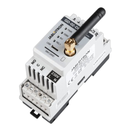
Figure 1: 1 – Low voltage terminals; 2 – GSM antenna;
3 – LED indicators; 4 – MicroUSB connector for connection to PC;
5 – SIM card slot; 6 – Power and mains terminals.
Terminals description:
Low voltage terminals:
TH+/TH-:
Input meant for connection of the GD-02T digital
temperature sensor. Other temperature sensors are not
supported. Mind the correct sensor polarity (red = TH+,
white = TH-). The measuring temperature range is from
-30 to +125 °C.
GND:
Common terminal for IN1, IN2 / REL2 and +5 V
terminals
IN1:
Allows connection of any floating contact such as a button,
switch, relay contact, etc. It is connected between the IN1
and GND terminals. The input recognizes contact
activation and also deactivation. A maximum of 24 V DC
can be connected to this terminal.
IN2/REL2: Universal input / output terminal. The IN2 input terminal
has similar behaviour to input IN1. It allows connection of
impulse output of an electrical meter for example. The
REL2 is a semiconductor signal output with an open
collector (switches to GND) and is protected by a current
fuse of 100 mA with a maximum connected voltage of
24 V DC.
+5V:
Power output 5V / 100 mA with protection against
shorting or overloading. This output has no backup
when the mains power fails. It serves for switching of
the external relay for example RB-524-DIN 250 V 16 A.
Power (high voltage) terminals:
NO, C, NC (REL1): Switching contact for power relay REL1 with
the parameters 230 V / 16 A. The relay has galvanically
separated contacts from the rest of the device and
complies with safety requirements for isolation of up to
4 kV. This output is not backed up when the mains
power fails. If the contact has been switched on, when
the mains fails, it switches off and after the mains
recovery the previous state can be restored (it depends
on the parameter on the "Setting" tab in the GD-Link
software).
L, N:
Terminals for connecting the mains (230 V AC / 50 Hz)
Notes:
If there is a requirement to install the GD-02-DIN controller in an
outdoor environment an installation housing with a high IP cover
index is needed.
The REL1 a REL2 outputs can be switched on independently for a
pre-defined time interval from 1 s to 24 hours (impulse). Both
outputs can have their own text instructions for activation and
deactivation.
For inputs IN1 and IN2 the time filter can be set from 0.1 s to
30 min in pre-set steps.
1 / 5
MNP51111
Advertisement

Subscribe to Our Youtube Channel
Related Manuals for jablotron GD-02-DIN


Summary of Contents for jablotron GD-02-DIN
- Page 1 Input 1 Red ON Input active Notes: Relay REL1 in standby mode If there is a requirement to install the GD-02-DIN controller in an REL1 (red) (Switched OFF) outdoor environment an installation housing with a high IP cover index is needed.
- Page 2 SIM card (turn the device on)! function (temperatures, SMS commands to control REL1 output, etc..). 1. Attach the GD-02-DIN onto the required place on the DIN rail. Consumption meter – Serves for the activation and set-up of the 2.
-
Page 3: Monitoring Mode
/ from the GND terminal. If the monitored device is equipped with for the required place and crossing the lower and upper limit reported by example a Fault output then it can be connected with the GD-02-DIN SMS. and reported by SMS and also dialling in. Up to 10 telephone numbers... -
Page 4: Thermostat Mode
IN2 and GND on The mode allows controlled switching of the heater by the REL1 output the GD-02-DIN (see Figure 6). The electricity meter can be single- to regulate the temperature in the premises. Pre-set the comfort and phase or three-phase. - Page 5 Radio transmissions ETSI EN 301 511 Current temperature requirement [PASSWORD] TMP JABLOTRON ALARMS a.s. hereby declares that the GD-02-DIN is in Example: 1234 TMP a compliance with the relevant Union harmonisation legislation: Directives No: 2014/53/EU, 2014/35/EU, 2014/30/EU, 2011/65/EU. The original of the conformity assessment can be found at www.jablotron.com...
Need help?
Do you have a question about the GD-02-DIN and is the answer not in the manual?
Questions and answers