Advertisement
WARNING
For Outdoor Use Only (outside any enclosure)
WARNING
1. Improper installation, adjustment, alteration, service or
maintenance can cause injury or property damage.
2. Read this instruction manual thoroughly before installing
or servicing this equipment.
3. Failure to follow these instructions could result in fire or
explosion, which could cause property damage, personal
injury or death.
4. This instruction manual contains important information
necessary for proper assembly and safe use this appliance.
5. Always keep this manual for convenient future reference.
WARNING
1. DO NOT store or use gasoline or other flammable vapors
and liquids in the vicinity of this or any other appliance.
2. An LP tank not connected for use should not be stored in
the vicinity of this or any other appliance.
DANGER
If you smell gas:
1. Shut off gas to the appliance.
2. Extinguish any open flames.
3. Open the lid.
4. If the odor continues, keep away from the appliance and
immediately call your gas supplier or fire department.
DANGER
Never operate this appliance unattended.
WARNING
Check for leaks every time prior to you light the grill, even if
purchased fully assembled. Gas leaks may cause a fire or
explosion.
Please read the instructions on Page 20.
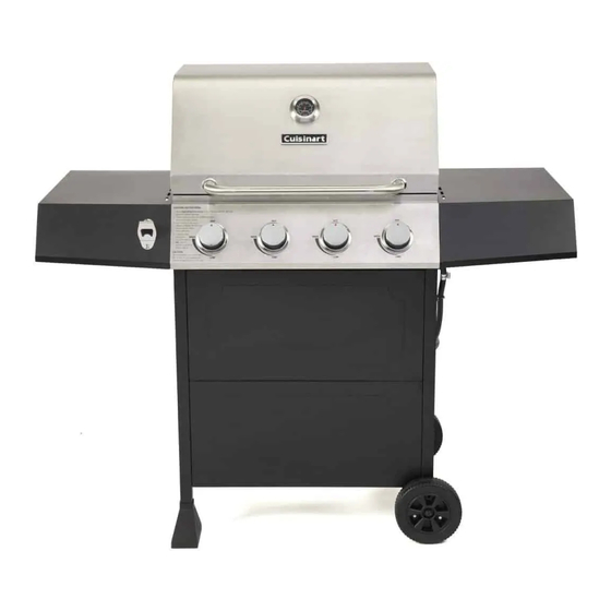
4 BURNER GAS GRILL
Customer Service Hotline
1-866-994-6390
DO NOT RETURN YOUR GRILL TO AMAZON.COM
Before running to your retailer, call our customer
service department at 1-866-994-6390 from 9:00am
to 5:00pm Eastern time, Monday through Friday.
1
Model NO.:CGG-7400
Advertisement

Related Manuals for Cuisinart CGG-7400


Summary of Contents for Cuisinart CGG-7400
-
Page 1: Cover
4 BURNER GAS GRILL Model NO.:CGG-7400 WARNING For Outdoor Use Only (outside any enclosure) WARNING 1. Improper installation, adjustment, alteration, service or maintenance can cause injury or property damage. 2. Read this instruction manual thoroughly before installing or servicing this equipment. -
Page 2: Table Of Contents
TABLE OF CONTENTS Cover …………….…………………………………….………...….………….………….….…………………..……..1 Table of contents……………………………………….………...….………….………………………….…….…..2 Safety Information…………………………………….………...….………….….………….……………..……..3 Exploded View……………….……………………………………………….......……….………..6 Parts list….……………..…..….……...…....……………..………………......7 Hardware Contents……………………………………………………………….………….……….….…..…..9 Assembly Instructions……………………..……………….……………………………………………...….….10 Connecting Regulator to the LP tank…………………..…………………….…......18 Check for Leaks…………….…………………………………….……………...….….……………………...…...20 L.P. Tank Information…………….…………………………………….……...….….……………….…..…..21 Lighting Instructions………….…………………………………….……...….….…………………..…..…...22 Care and Maintenance……………………………….………………………………………..………….……...23 Troubleshooting …………………………………………………………………..….…………………..………...27 Warranty………………………………………………………………………………………………………..………..28 Distributed by: The Fulham Group Newton, MA Manufacturer:... -
Page 3: Safety Information
SAFETY INFORMATION IMPORTANT: ALL INSTRUCTIONS AND SAFEGUARDS ON THIS SECTION MUST BE FOLLOWED TO PREVENT FIRE, DAMAGE AND/OR INJURY. This grill is for outdoor use only, and shall not be used in a building, garage, or any other enclosed area. Do NOT operate, light or use this appliance within 8 feet of walls, structures or buildings. - Page 4 SAFETY INFORMATION The LP gas cylinder used with this appliance must be: (a) Constructed and marked in accordance with the Specifications for LP-Gas Cylinders of the U.S. Department of Transportation (D.O.T.) or the National Standard of Canada, CAN/CSA-B339, Cylinders, Spheres and Tubes for Transportation of Dangerous Goods;...
- Page 5 SAFETY INFORMATION CALIFORNIA PROPOSITION 65 WARNING: (a)The burning of gas cooking fuel generates some byproducts which are on the list of substances known by the State of California to cause cancer, reproductive harm, or other birth defects. To reduce exposure to these substances, always operate this unit according to the use and care manual, ensuring you provide good ventilation when cooking with gas.
-
Page 6: Exploded View
EXPLODED VIEW... -
Page 7: Parts List
PARTS LIST PART DESCRIPTION PART NO ※Lid Assembly 2824BP01 ※Lid Axis 2411017 Lid Handle Bezel 5201176 Lid Handle 5206522 Temperature Gauge Bezel 5208127 Temperature Gauge 2414112 ※Lid Spacer 2100158 ※Firebox Assembly 5213554 Right Side Shelf 5210046 Drip Tray 5213563 Grease Cup 5210023 Rear Beam 5210058... - Page 8 PARTS LIST PART DESCRIPTION PART NO ※Regulator & Hose assembly 5210038 Control Knob 2403612 ※Knob Bezel 5210382 ※Manifold & Gas Valve Assembly 5213521 ※Control Panel 5213555 ※Bottle Opener 5014838 Left Side Shelf 5210045 ※Tube Burner Ignition Pin 2413901 ※Tube Burner 2413900 ※R Pin 2307001...
-
Page 9: Hardware Contents
HARDWARE CONTENTS AA M6X16 mm Screw BB M10 Fasten Nut CC M6 Washer ASSEMBLY PREPARATION THIS UNIT IS HEAVY. TWO PEOPLE ARE REQUIRED FOR SAFE ASSEMBLY! Some parts may contain sharp edges. Wear protective gloves if necessary. Read and follow all safety statements, warnings, assembly instructions and use and care instructions before attempting to assemble and use. -
Page 10: Assembly Instructions
ASSEMBLY INSTRUCTIONS IMPORTANT: ASSEMBLE ON FLAT AND SOFT SURFACE TO AVOID SCRATCHING. 1. Put Left Back Leg (27) and Left Front Leg (25) into Leg End Caps (23) as shown. 2. Assemble Left Side Cart Frame. 2.1. Loosen 6pcs pre-assembled M6X16mm Screws from “X” position and leave the screw heads protruding approximately 5mm. - Page 11 ASSEMBLY INSTRUCTIONS 3. Assemble Right Side Cart Frame. 3.1. Loosen 6pcs pre-assembled M6X16mm Screws from “X” position, and leave the screw heads protruding approximately 5mm. 3.2. Hang Right Side Beam (17) and Drip Tray Support (14) to Right Front Leg (18) and Right Back Leg (13) ,then fasten the screws on “X”...
- Page 12 ASSEMBLY INSTRUCTIONS 5. Attach Rear Beam 5.1. Loosen 4pcs pre-assembled M6X16mm Screws from Left Back Leg (27) and Right Back Leg (13), leave the screw heads protruding approximately 5mm. 5.2. Hang Rear Beam (12) onto Left & Right Back Leg on the screws and hand tighten only the screws on this point.
- Page 13 ASSEMBLY INSTRUCTIONS 7. Insert the Drip Tray (10) and Grease Cup (11) into the cart as shown. 8. Require two people to lift and place the Firebox Assembly onto the cart and fasten 4pcs AA Screws as shown. AA M6X1 6 mm Black Screw AA M6X16 mm Screw Screw...
- Page 14 ASSEMBLY INSTRUCTIONS 9. Assemble Lid Handle and Temperature Gauge 9.1. Attach Lid Handle (4) together with Lid Handle Bezels (3) onto Lid Assembly and fasten the screws. 9.2. Attach Temperature Gauge (6) together with Temperature Gauge Bezel (5) onto Lid Assembly and fasten the screws.
Need help?
Do you have a question about the CGG-7400 and is the answer not in the manual?
Questions and answers