thomann THE BOX MBA120W MKII User Manual
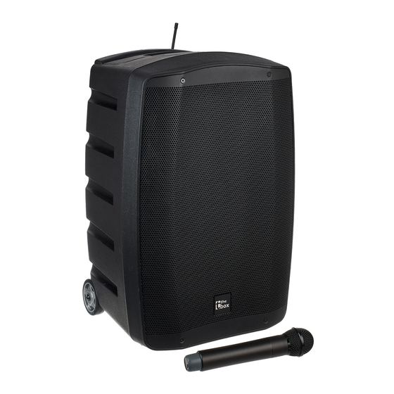
Battery-powered speaker
Hide thumbs
Also See for THE BOX MBA120W MKII:
- User manual (68 pages) ,
- User manual (64 pages) ,
- User manual (60 pages)
Table of Contents
Advertisement
Advertisement
Table of Contents

Related Manuals for thomann THE BOX MBA120W MKII


Summary of Contents for thomann THE BOX MBA120W MKII
- Page 1 MBA120W MKII battery-powered speaker user manual...
- Page 2 Musikhaus Thomann Thomann GmbH Hans-Thomann-Straße 1 96138 Burgebrach Germany Telephone: +49 (0) 9546 9223-0 E-mail: info@thomann.de Internet: www.thomann.de 29.08.2019, ID: 466279...
-
Page 3: Table Of Contents
Table of contents Table of contents General information..........................5 1.1 Further information........................... 6 1.2 Notational conventions........................7 1.3 Symbols and signal words....................... 8 Safety instructions..........................10 Features............................... 17 Installation..............................19 4.1 Battery operation..........................20 4.2 Remote control..........................22 4.3 Microphone............................23 Connections and operating elements................... - Page 4 Table of contents Protecting the environment......................56 battery-powered speaker...
-
Page 5: General Information
Our products and user manuals are subject to a process of continuous development. We there‐ fore reserve the right to make changes without notice. Please refer to the latest version of the user manual which is ready for download under www.thomann.de. MBA120W MKII... -
Page 6: Further Information
General information 1.1 Further information On our website (www.thomann.de) you will find lots of further information and details on the following points: Download This manual is also available as PDF file for you to download. Use the search function in the electronic version to find the topics of Keyword search interest for you quickly. -
Page 7: Notational Conventions
General information 1.2 Notational conventions This manual uses the following notational conventions: Letterings The letterings for connectors and controls are marked by square brackets and italics. Examples: [VOLUME] control, [Mono] button. Displays Texts and values displayed on the device are marked by quotation marks and italics. Examples: ‘24ch’... -
Page 8: Symbols And Signal Words
General information 1.3 Symbols and signal words In this section you will find an overview of the meaning of symbols and signal words that are used in this manual. Signal word Meaning DANGER! This combination of symbol and signal word indicates an immediate dangerous situation that will result in death or serious injury if it is not avoided. - Page 9 General information Warning signs Type of danger Warning – high-voltage. Warning – danger zone. MBA120W MKII...
-
Page 10: Safety Instructions
Safety instructions Safety instructions Intended use This device is designed for sound reinforcement. Use the device only as described in this user manual. Any other use or use under other operating conditions is considered to be improper and may result in personal injury or property damage. No liability will be assumed for damages resulting from improper use. - Page 11 Safety instructions DANGER! Danger for children Ensure that plastic bags, packaging, etc. are disposed of properly and are not within reach of babies and young children. Choking hazard! Ensure that children do not detach any small parts (e.g. knobs or the like) from the unit.
- Page 12 Safety instructions DANGER! Electric shock caused by high voltages inside Within the device there are areas where high voltages may be present. Never remove any covers. There are no user-serviceable parts inside. Do not use the device if covers, protectors or optical components are missing or damaged.
- Page 13 Safety instructions CAUTION! Possible hearing damage The device can produce volume levels that may cause temporary or permanent hearing impairment. Over an extended period of time, even levels that seem to be uncritical can cause hearing damage. Decrease the volume level immediately if you experience ringing in your ears or hearing impairment.
- Page 14 Safety instructions NOTICE! Power supply Before connecting the device, ensure that the input voltage (AC outlet) matches the voltage rating of the device and that the AC outlet is protected by a residual current circuit breaker. Failure to do so could result in damage to the device and possibly injure the user.
- Page 15 Safety instructions NOTICE! Possible damage by leaking batteries Leaking batteries can cause permanent damage to the device. Take batteries out of the device if it is not going to be used for a longer period. NOTICE! Possible damage due to incorrect storage Deep discharge can cause batteries to become permanently damaged or lose some of their capacity.
- Page 16 This equipment uses a frequency range that is free of charge and registration within the European Union. For more information, please visit: http://www.thomann.de. When operating, make sure that transmitter and receiver are set to the same channel. Never set more than one transmitter to the same channel.
-
Page 17: Features
Features Features The mobile PA system is characterized by the following features: Compact all-in-one system Power supply via AC mains power or through the built-in rechargeable batteries 10" woofer, 1" compression driver 120 W output power in mains operation, 80 W in battery operation Frequency range 55 Hz …... - Page 18 Features Spacious storage compartment for accessories embedded in the housing Compatible cover (Item no. 382254) not included battery-powered speaker...
-
Page 19: Installation
Installation Installation Unpack and check carefully there is no transportation damage before using the unit. Keep the equipment packaging. To fully protect the product against vibration, dust and moisture during transportation or storage use the original packaging or your own packaging material suitable for transport or storage, respectively. -
Page 20: Battery Operation
Installation 4.1 Battery operation You can also operate the device independently of the mains power supply with the supplied integrated VRLA rechargeable batteries. battery-powered speaker... - Page 21 Installation Installation and replacement of Disconnect the device from the mains. VRLA rechargeable batteries Remove the mounting screw of the battery compartment cover. Remove the two mounting screws of the fixing plate. Use only suitable VRLA rechargeable batteries of the same size and type (see Ä...
-
Page 22: Remote Control
Installation Charge the batteries completely after each use and during storage at least every two months. The maximum storage time for VRLA rechargeable batteries without charge cycle is six months. After this period is exceeded, the affected batteries may be unusable and must be disposed of properly. -
Page 23: Microphone
Installation 4.3 Microphone Installation and replacement of batteries The battery compartment of the microphone is located under the grip sleeve and shares the same thread with the microphone capsule. To access the battery compartment without acci‐ dentally unscrewing the microphone capsule, hold the microphone at the bottom of the antenna base and turn the sleeve as shown. -
Page 24: Connections And Operating Elements
Connections and operating elements Connections and operating elements Rear view - overview battery-powered speaker... - Page 25 Connections and operating elements Partial view A MBA120W MKII...
- Page 26 Connections and operating elements 1 Channel display. Double-digit display for selecting and displaying the radio transmission channel (range ‘01’ … ‘16’ ). 2 [RF | AF] The red indicator LED [RF] lights up when a radio signal is transmitted between microphone and receiver. The green indicator LED [AF] lights up when an audio signal from an external device is present.
- Page 27 Connections and operating elements 6 [DOWN | UP] Pushbutton for selecting the radio transmission channel. Proceed as follows to find a free channel: Turn the radio microphone (transmitter) and receiver (with the controller [POWER-VOL]) off. Use [DOWN | UP] to click through the available channels. If the displayed channel is already in use, the red LED [RF].
- Page 28 Connections and operating elements Partial view B battery-powered speaker...
- Page 29 Connections and operating elements 10 SD card slot. 11 Display ( Ä ‘Display’ on page 37). 12 USB port. 13 Selection and control buttons: [MODE] Selection button. Press this button to select an audio source: SD card, USB input or Bluetooth port. The active source is shown on the display.
- Page 30 Connections and operating elements Selection button. Press the button repeatedly to activate a playback mode. The active mode and the title of the cur‐ rent track will appear on the display: Normal ‘N’ . All tracks of the selected audio source are played in succession according to the MP3 file date. The prerequisite for this is that a subdirectory with the desired titles has been created on the data medium.
- Page 31 Connections and operating elements 14 [LEVEL] Gain control for channel 3. Use this control to adjust the level of the input signal in Channel 3. 15 [ON | LIMIT] Indicator LED (green). This LED lights solid in normal operation and flickers when the box is overdriven. In this case, turn the gain control of the active channel down to reduce the level of the input signal.
- Page 32 Connections and operating elements 20 [CH2] Signal input for channel 2, designed as XLR / 1/4" jack combo socket, beneath toggle switch for LINE and MIC input signal level. 21 [CH1] RCA input sockets to connect an external audio device to channel 1. 22 [LINE IN] 3.5 mm input socket to connect an external audio device to channel 1.
- Page 33 Connections and operating elements Partial view C MBA120W MKII...
- Page 34 Connections and operating elements 26 [BATTERY LEVEL] State of charge indicators. All four LEDs light when batteries are fully charged. When capacity decreases, the green LEDs 3, 2 to 1 go out one by one. If only the red LED lights the remaining battery capacity is low. Then connect the device to the mains power to charge the batteries.
- Page 35 Connections and operating elements Partial view D MBA120W MKII...
- Page 36 Connections and operating elements 31 Mounting screws of the fixing plate. 32, 33 VRLA batteries 1 and 2. Observe the correct polarity when wiring the batteries. Connect the red cable to the positive pole of battery 1 and the black cable to the negative pole of battery 2. Use the blue cable to connect the negative pole of battery 1 to the positive pole of battery 2.
- Page 37 Connections and operating elements Display a Play/Pause. b Endless loop. c Number of the currently playing track and number of tracks in the current folder. d Selected EQ setting. e Bit rate and file type of the currently playing track. f Symbol for the selected data source.
- Page 38 Connections and operating elements Remote control battery-powered speaker...
- Page 39 Connections and operating elements 31 [CHANNEL] No function. 32 [VOL– / VOL+] To decrease or increase the volume. 33 [PREV / NEXT] Forward (skip to the next track) or backward (skip to the previous track). 34 Numeric keypad for direct access to tracks. 35 [MODE] Selection button.
- Page 40 Connections and operating elements 36 [ENTER] This button opens a menu with the following options: ‘EQ’ – selects an equalizer setting, corresponds to the key [EQ] on the remote. ‘PLAY MODE’ – selects a play mode, corresponds to the key on the unit.
- Page 41 Connections and operating elements 38 [EQ] Selects an EQ setting: ‘NOR’ – Normal ‘POP’ – Pop music ‘ROCK’ – Rock music ‘JAZZ’ – Jazz ‘CLAS’ – Classic music ‘COU’ – Country music ‘BAS’ – Bass boost 39 [PLAY/PAUSE] Play / pause button to start / stop playback. MBA120W MKII...
- Page 42 Connections and operating elements Microphone battery-powered speaker...
- Page 43 Connections and operating elements 40 Microphone head grill to prevent damage and to reduce wind and breath noise. 41 Lower housing part. Unscrew to open. 42 [BATT] This LED shows the state of the batteries. When the microphone is turned on and the capacity of the battery is suffi‐ cient, the LED lights green.
- Page 44 Connections and operating elements 46 [GAIN] Control to adjust the microphone sensitivity. 47 [H/L] Switch for selecting the transmission level. In ‘L’ position, a low level is used to save the batteries. As a result, the range is reduced to about 10 m. In ‘H’ position, a high level is used for an expanded transmission range (about 30 m). This reduces battery life.
- Page 45 Connections and operating elements Playback via Bluetooth Establishing connection to Bluetooth device Follow the instructions given in the manual of the Bluetooth device and turn it on. Place it near the device. Press [MODE] and select the Bluetooth interface as the source for playback. After a few seconds your Bluetooth device is detected.
- Page 46 Connections and operating elements – ‘Lowbass’ – Bass boost ‘Deleted paired info’ – erases all information on last link with a Bluetooth device. Try this option to solve problems establishing a Bluetooth connection. ‘Device Information’ – shows information about the name and address of the Bluetooth interface of the device on the display.
-
Page 47: Technical Specifications
Technical specifications Technical specifications Amplifier / speaker Speaker Two-way system with 1" compression driver and 10" woofer Input connections 2 × XLR / 1/4" combo socket for micro‐ phone / line input with switchable sensi‐ tivity 1 × 3.5 mm phone socket for line input 2 ×... - Page 48 Technical specifications 80 W (battery operation) Frequency range 55 Hz … 18 kHz, –3 dB Radio link Carrier frequency UHF band (863 MHz … 865 MHz) NF frequency response 60 Hz … 16 kHz, –3 dB Modulation type Frequency modulation (FM) Signal-to-noise ratio >...
- Page 49 Technical specifications 2 × 12 V lead-gel rechargeable batteries (VRLA batteries, 5 Ah each), maintenance-free Recommended types: Ritar RT1250 Fiamm FG20451 Fuse 115 V: 5 mm × 20 mm, 2 A, 250 V, slow-blow 230 V: 5 mm × 20 mm, 1 A, 250 V, slow-blow Operating time per battery charge Music: approx.
- Page 50 Technical specifications Further information Incl. player Incl. microphone Incl. radio system Incl. subwoofer Incl. cover No (optional, item no. 382254) battery-powered speaker...
-
Page 51: Plug And Connection Assignment
Plug and connection assignment Plug and connection assignment Introduction This chapter will help you select the right cables and plugs to connect your valuable equip‐ ment in such a way that a perfect sound experience is ensured. Please note these advices, because especially in ‘Sound & Light’ caution is indicated: Even if a plug fits into the socket, an incorrect connection may result in a destroyed power amp, a short circuit or ‘just’... - Page 52 Plug and connection assignment In a professional environment, therefore, the balanced transmission is preferred, because this enables an undisturbed transmission of signals over long distances. In addition to the conduc‐ tors ‘Ground’ and ‘Signal’, in a balanced transmission a second core is added. This also transfers the signal, but phase-shifted by 180°.
- Page 53 Plug and connection assignment 1/4" TRS phone plug (mono, bal‐ anced) Signal (in phase, +) Signal (out of phase, –) Ground Three-pole 1/8" mini phone jack (stereo, unbalanced) Signal (left) Signal (right) Ground, shielding MBA120W MKII...
- Page 54 Plug and connection assignment XLR plug (balanced) Ground, shielding Signal (in phase, +) Signal (out of phase, –) Shielding on plug housing (option) RCA connection Drawing and table indicate the pin assignment of an RCA plug. Signal Ground, shielding battery-powered speaker...
-
Page 55: Cleaning
Cleaning Cleaning Device components Clean the device components that are accessible from the outside regularly. The cleaning fre‐ quency depends on the operating environment: damp, smoky or particularly dirty environ‐ ments can cause greater accumulation of dirt on the device components. Clean with a dry soft cloth. - Page 56 Protecting the environment Protecting the environment Disposal of the packaging mate‐ rial For the transport and protective packaging, environmentally friendly materials have been chosen that can be supplied to normal recycling. Ensure that plastic bags, packaging, etc. are properly disposed of. Do not just dispose these materials with your normal household waste, but make sure that they are fed to a recovery.
- Page 57 Protecting the environment Disposal of your old device This product is subject to the European Waste Electrical and Electronic Equipment Directive (WEEE) in its currently valid version. Do not dispose with your normal household waste. Dispose this device through an approved waste disposal firm or through your local waste facility.
- Page 58 Notes battery-powered speaker...
- Page 60 Musikhaus Thomann · Hans-Thomann-Straße 1 · 96138 Burgebrach · Germany · www.thomann.de...
Need help?
Do you have a question about the THE BOX MBA120W MKII and is the answer not in the manual?
Questions and answers
how do you recharge the hand mic
The Thomann MBA120W MKII handheld microphone uses LR6 AA (1.5 V) batteries or rechargeable Ni-MH batteries. To recharge it, remove the rechargeable Ni-MH batteries from the microphone and charge them using an external battery charger, as the microphone itself does not have built-in charging capability.
This answer is automatically generated