Table of Contents
Advertisement
Quick Links
Advertisement
Table of Contents

Related Manuals for Sewhacnm SI 4000


Summary of Contents for Sewhacnm SI 4000
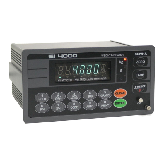
- Page 1 Digital Weighing Indicator SI 4000 Instruction Manual Version 1.11 (2007 06)
- Page 2 DIGITAL WEIGHING INDICATOR SI 4000 CONTENTS 1. Before Installation 4 page --------------- 1-1. Caution / Warning Marks --------------- 4page 1-2. Other Marks --------------- 4page 1-3. Copy Rights --------------- 4page 1-4. Inquiries --------------- 4page 2. Introduction 5 page --------------- 2-1. Introduction...
- Page 3 DIGITAL WEIGHING INDICATOR SI 4000 6. Interface 52 page --------------- 6-1. Serial Interface (RS-232C) --------------- 52 page 6-2. Current Loop Interface --------------- 55 page 6-3. Print Interface (Option 01 : Centronics Parallel Interface) --------------- 56 page 6-4. Analog Output Interface (Option 02 : 0~10V)
-
Page 4: Before Installation
1-3. Copy Rights 1). All Right and Authority for this Manual is belonged to Sewhacnm Co.,Ltd. 2). Any kinds of copy or distribution without Sewhacnm Co.,Ltd’s permission will be prohibited. 1-4. Inquiries If you have any kinds of inquiries for this model, please contact with your local agent or Head Office. - Page 5 With 2ports serial port communication and High Speed A/D conversion performance will lead you to precise weighing process. This “SI 4000” Weighing Indicator is simple application model, and it can be used for “Truck Scale, Platform Scale, Tank Scale. Please review this instruction Manual and learn more about information about “SI 4000”.
- Page 6 DIGITAL WEIGHING INDICATOR SI 4000 3. SPECIFICATION 3-1. Analog Input & A/D Conversion Input Sensitivity 0.3㎶ / Digit Load Cell Excitation DC 10V ( - 5V ~ + 5V ) Max. Signal Input Voltage Max.32mV [Zero] ±16PPM/℃ Temperature Coefficient [Span] ±3.5PPM/℃...
- Page 7 DIGITAL WEIGHING INDICATOR SI 4000 3-3. General Specification AC110/220V±10%), 50/60Hz, about 30VA Power Supply Operating Temperature Range -10℃ ~ 40℃ Operating Humidity Range Under 85% Rh (non-condensing) External Dimension 200mm(W)x105mm(H)x165mm(L) Net Weight(kg) About 2.3kg About 3.0kg Gross Weight(kg) ※ AC 110V, Power supply is an optional before ex-factory.
- Page 8 DIGITAL WEIGHING INDICATOR SI 4000 3-5-1. Status Lamp (ANNUNCIATORS) : “▼” Lamp is “ON”. When the weight is Steady, “▼” Lamp is turn on. Steady When the current weight is Zero, “▼” Lamp is turn on. Zero (Displayed weight is Zero, “▼” Lamp is turn on.) Tare function is set, “▼”...
- Page 9 DIGITAL WEIGHING INDICATOR SI 4000 Release set “HOLD” function. Under “TARE” setting, you can select weight display mode. First input, Gross Weight will be displayed, second input, Net weight will be displayed. ※ This key will be activated only under “TARE” set.
- Page 10 DIGITAL WEIGHING INDICATOR SI 4000 To Set “Auto Print” mode. Under Auto Print Mode, When the weight will be increased over than “Empty Range” and steady, steady weight will be printed automatically. ※ Under “Auto Print” mode, Steady weight will be printed and Save on Sub-Total and Grand-Total Data.
- Page 11 DIGITAL WEIGHING INDICATOR SI 4000 3-6. Rear Panel Option Card(1) Option Card(2) AC Power Input Load cell Connector External Input Serial Port(Standard) ① POWER AC IN - Power switch : Power on/off switch. - Fuse : AC250V / 0.5A , φ5.25 , 20mm.
- Page 12 DIGITAL WEIGHING INDICATOR SI 4000 4. INSTALLATION 4-1. External Dimension & Cutting Size (External Dimension) (unit : mm) 162.0 (Cutting Size) (unit : mm)
- Page 13 DIGITAL WEIGHING INDICATOR SI 4000 4-2. Assembly...
- Page 14 DIGITAL WEIGHING INDICATOR SI 4000 4-3. Load Cell Installation 4-3-1. Load Cell Connector Specification White Green Blue Shield 4-3-2. Load Cell Installation 1). You can connect Max. 8pcs of same capacity Load cells at once. (350Ω) 2). You have to make horizontal balance on the ground.
- Page 15 DIGITAL WEIGHING INDICATOR SI 4000 4-3-3. Load Cell Wire Connection 1). Please connect Indicator’s connector and Load cell cable basis on each color. 2). It is possible to connect Max. 8pcs same capacity load cells with parallel. (350Ω) 3). LOAD CELL Connector Standard : N16 - 05 4).
- Page 16 SI 4000 4-3-4. Formula to plan the precise weighing system This “SI 4000” weighing controller’s Max. input sensitivity is 0.2㎶ / Digit. And for precise weighing system, the following formula must be satisfied. Caution : “Input sensitivity” means Min. output voltage variation of weighing part to change 1digit. So, Cautions please do not make large input voltage to make reliable weighing system.
- Page 17 DIGITAL WEIGHING INDICATOR SI 4000 5. SET-UP 5-1. Calibration Adjust weight balance between “Real weight” on the load cell(Weight Part) and “Displayed weight of Indicator”. When you replace LOAD CELL or Indicator, you have to do Calibration process once again 5-2.
- Page 18 DIGITAL WEIGHING INDICATOR SI 4000 Step No.2 - Setting “Decimal Point” Decimal point position select with “0” key Press “Enter” and move the next step. Under this step, define the optimal position or Decimal point. Whenever pressing key, Decimal point will be changed, like XXX. – XX.X – X.XX - .XXX The Max.
- Page 19 DIGITAL WEIGHING INDICATOR SI 4000 Step No.4 - Measure the “DEAD Weight of Weighing Scale. Memorize “DEAD weight” of Weighing Machine Indicator will search “DEAD weight” during with “Enter”. 5sec, automatically. Under this step, measure the “DEAD Weight of Weighing Scale”.
- Page 20 DIGITAL WEIGHING INDICATOR SI 4000 Input prepared Test weight value and press key, then message will be displayed. Then load Test weight on weighing scale and press key. Then, indicator will make adjustment for “Standard weight value” and calculate “Span value”.
- Page 21 DIGITAL WEIGHING INDICATOR SI 4000 5-3. Simulation Calibration Mode (Calibrate without Test weight) Through this “Simulation Calibration Mode” you can make simple calibration without Test weight. This calibration mode uses “Load cells’ max. capacity” and “Max. Output Rate(mV)”, the weight adjustment degree might be less than “Test weight Calibration”.
- Page 22 DIGITAL WEIGHING INDICATOR SI 4000 Please input this max. capacity of load cell value with No. keys. After finishing input, press key and save and move to next step. Caution ※ If the plural No. of load cells are installed, please make sum the all load cells capacity and input.
- Page 23 DIGITAL WEIGHING INDICATOR SI 4000 Caution ※ (Max. capacity value / division value) can not be over 20,000.(as Indicator resolution is 1/200,00). If the value is over 20,000, Error message “ Err 01 “ will be displayed and move back “CAPA” mode again.
- Page 24 DIGITAL WEIGHING INDICATOR SI 4000 The Output rate is stated on “Test report” or “Label” and please input this value with No. keys. Normally, the Output rate will be 4digits under Zero, then input 4digits and input “0” additionally and make full 6digits.
- Page 25 DIGITAL WEIGHING INDICATOR SI 4000 5-4. Set-up Set-up means set the F-function and make SI 4000 weighing controller will perform more accuracy. (Considering external / internal environmental condition) 5-4-1. Enter the Set-up Mode 1). Method : Press key for 4sec. Then you can enter “F-Test” mode. Under this mode, press No.1 key and enter the “F-function”...
- Page 26 DIGITAL WEIGHING INDICATOR SI 4000 5-5. F-Function List General Function Setting Weight-Back up selection 0, 1 0 ~ 9 MOTION BAND Range setting ZERO TRACKING Compensation 0 ~ 9 Range setting Auto Zero Range setting 00 ~ 99 Digital Filter setting 00 ~ 19 “Zero/Tare”...
- Page 27 DIGITAL WEIGHING INDICATOR SI 4000 Communication Mode setting 0, 1, 2, 3 Parity Bit selection Mode 0 ~ 9 Serial Communication Speed selection 0, 1 DATA Transference Method selection Print Port selection 0, 1 (Under F32-01 setting, only) “Check-Sum” detection selection...
- Page 28 DIGITAL WEIGHING INDICATOR SI 4000 Other setting Empty Range setting X X X X X X X. X X X X X Span calibration value check DATE check/change XX. XX. XX TIME check/change XX. XX. XX XX. XX. XX Program & Hard ware Version Check Production Date Check X.XX X.XX.
- Page 29 “Manual initialization”, press “0” key or enter “Calibration mode”. Weight Back up Mode ※ Under this mode, SI 4000 memories “Zero” value of weighing part. So, when the power is recovered SI 4000 can display material weight. Motion Band Range setting This is set “Steady”...
- Page 30 DIGITAL WEIGHING INDICATOR SI 4000 Steady Break point Motion Band Range Motion Band Zero Range Motion Band Range In this case, if you increase “Motion Band Range”(F03 -03), the “Steady Break point” will be in the steady ※ range, and indicator will display “Steady” condition. – (Set value “1” means 50% of Digit)
- Page 31 DIGITAL WEIGHING INDICATOR SI 4000 Weight Zero breaks Display Current weight 0.075kg (1.5ⅹdigit) Display Zero time about 5msec. Auto Zero Range setting Within the “Auto Zero” range, weighing part is steady, indicator will display current weight as “Zero” ∫ If the weighing part is not “Steady”, indicator will display current weight.
- Page 32 DIGITAL WEIGHING INDICATOR SI 4000 Zero /Tare key Operation mode selection ● Activate when “Steady” condition, only Always activated Zero key Operation Range selection Activated within 2% of Max. Capacity Activated within 5% of Max. Capacity ● Activated within 10% of Max. Capacity Activated within 20% of Max.
- Page 33 DIGITAL WEIGHING INDICATOR SI 4000 “STEADY” condition check time setting During the set time period, estimate weighing part’s “STEADY” condition and display. ∫ If you set small value, indicator will take “STEADY” fast, if you set large value, indicator will take “STEADY” slow.
- Page 34 DIGITAL WEIGHING INDICATOR SI 4000 Auto HOLD RESET Time Setting Under “HOLD” setting, Automatic RESET time setting mode. ∫ “00” setting : Auto HOLD reset function not use. “05” setting : After 0.5sce, Automatic HOLD reset. HOLD Delay time setting After Pressing “HOLD”...
- Page 35 DIGITAL WEIGHING INDICATOR SI 4000 ■ Communication Mode setting (Serial Port 1. - Standard installed port) Parity Bit selection Mode ● No Parity Odd Parity Even Parity Serial Communication Speed selection 2,400bps 4,800bps ● 9,600bps 14,400bps 19,200bps 28,800bps 38,400bps 57,600bps...
- Page 36 DIGITAL WEIGHING INDICATOR SI 4000 ※ Through this function, you can selection print port, where indicator takes a “Print Command” from P.C. If you choose F33-00, the print data will be transfer to P.C with print format. If you choose the other port, the print data will be transfer through the other port.
- Page 37 DIGITAL WEIGHING INDICATOR SI 4000 AUTO Print Mode Selection ● When Weight is steady over than Empty Range, Automatically print. Over than Empty Range, Steady Lamp is “ON”, Automatically Print. ※ -01 setting : Just check “STEADY LAMP condition, and if the LAMP is ON, Auto print, Lamp is OFF, not printing.
- Page 38 DIGITAL WEIGHING INDICATOR SI 4000 Paper Withdraw Rate setting (After SUB/GRAND Total Print) ∫ Whenever set value increased, 1line will be added. Paper Withdraw Rate setting (After Continuous/Single Print) ∫ Whenever set value increased, 1line will be added. Printing Language Selection (If you install on Standard Serial Port) ●...
- Page 39 DIGITAL WEIGHING INDICATOR SI 4000 ■ Other Setting Under “Other setting mode”, you can not move to other function directly. ※ Press key and move to F01 and move to other function No. directly. EMPTY Range setting You can set “EMPTY” Range.
- Page 40 DIGITAL WEIGHING INDICATOR SI 4000 Production DATE Check Check the Product’s Production Year and Month. You can only check the s erial No. (Modification is prohibited) ※ ■ Communication Mode setting (Serial Port 2. - Optional Serial port) This setting will be activated only when “Optional Serial Port” is installed.
- Page 41 DIGITAL WEIGHING INDICATOR SI 4000 serial port, Please refer F65, 66, 67, 68. Print port selection (Under F32-01 setting, only) ● Same port as using for Command Mode. The other port. ※ Through this function, you can selection print port, where indicator takes a “Print Command” from P.C. If you choose F33-00, the print data will be transfer to P.C with print format.
- Page 42 DIGITAL WEIGHING INDICATOR SI 4000 AUTO Print Mode Selection ● When Weight is steady over than Empty Range, Automatically print. Over than Empty Range, Steady Lamp is “ON”, Automatically Print. ※ -01 setting : Just check “STEADY LAMP condition, and if the LAMP is ON, Auto print, Lamp is OFF, not printing.
- Page 43 DIGITAL WEIGHING INDICATOR SI 4000 C. External Display (SE 6005 / SE 6105 / SE 6300) Standard Serial Port Setting F32-00 : Simplex Mode Setting F35-00 : Data Transference Mode F36-00 : Stream Mode Fix F37-00/01/02 : Transferred Data format setting.
- Page 44 DIGITAL WEIGHING INDICATOR SI 4000 CASE 2. Standard Serial Port Setting – Data Transference Mode(P.C Monitoring) F32-00 : Simplex Mode setting F35-00 : Data Transference Mode F36-00/01/02 : 00(Steam Mode) 01(When “Steady” Condition, 1time transfer) 02(When key input, 1time transfer)
- Page 45 DIGITAL WEIGHING INDICATOR SI 4000 CASE 2. Standard Serial Port Setting – External Display Mode F32-00 : Simplex Mode Setting F35-00 : Data Transference Mode F36-00 : Stream Mode Fix F37-00/01/02 : Transferred Data format setting. F40-00 : Under “External Display” mode, F40-00 Fix Optional Serial Port Setting –...
- Page 46 DIGITAL WEIGHING INDICATOR SI 4000 CASE 2. Standard Serial Port Setting – Serial Print Mode F62-00 : Simplex Mode setting F65-01 : Print Mode setting : Auto Print Mode (User Select Option) Optional Serial Port Setting – Command Mode F62-01 : Command Mode F63-00(Nominate Printing port for “PRINT COMMAND”)
- Page 47 DIGITAL WEIGHING INDICATOR SI 4000 CASE 2. Standard Serial Port Setting – External Display Mode F32-00 : Simplex Mode Setting F35-00 : Data Transference Mode F36-00 : Stream Mode Fix F37-00/01/02 : Transferred Data format setting. F40-00 : Under “External Display” mode, F40-00 Fix Optional Serial Port Setting –...
- Page 48 DIGITAL WEIGHING INDICATOR SI 4000 CASE 2. Standard Serial Port Setting – Serial Print Mode F32-00 : Simplex Mode setting F35-01 : Print Mode setting F38-00/01 : 00 setting : Manual Print Mode( key input, 1time Print out) 01 setting : Auto Print Mode (When “Steady” Condition, 1time auto Print out) Optional Serial Port Setting –...
- Page 49 DIGITAL WEIGHING INDICATOR SI 4000 CASE 2. Standard Serial Port Setting – Serial Print Mode F32-00 : Simplex Mode setting F35-01 : Print Mode setting : Auto Print Mode (User Select Option) Optional Serial Port Setting – External Display Mode...
- Page 50 DIGITAL WEIGHING INDICATOR SI 4000 H. Standard Serial Port & Optional Serial Port – Data Transference Mode(P.C Monitoring) Standard Serial Port setting – Data Transference Mode F32-00 : Simplex Mode setting F35-00 : Data Transference Mode F36-00/01/02 : 00(Steam Mode) 01(When “Steady”...
- Page 51 DIGITAL WEIGHING INDICATOR SI 4000 J. Standard Serial Port & Optional Serial Port – Serial Print Mode Standard Serial Port Setting – Serial Print Mode F32-00 : Simplex Mode setting F35-01 : Print Mode setting : Auto Print Mode (User Select Option) Optional Serial Port Setting –...
- Page 52 DIGITAL WEIGHING INDICATOR SI 4000 6. INTERFACE 6-1. Serial Interface (RS-232C) RS-232C Serial Interface is sensitive/weak for electric Noise. So, please isolate with AC power cable and use shield cable to reduce the electric noise effect. 6-1-1. Signal Format ①. Type : EIA-RS-232C ②.
- Page 53 DIGITAL WEIGHING INDICATOR SI 4000 ②. Header 2. : NT : Net-Weight GS : Net-Weight, under TARE. ③. Data Bit(Number) 2B(H) : “+” Plus 2D(H) : “-“ Minus 2D(H) : “ “ Space 2E(H) : “.” Decimal Point ④. Unit : kg, g, t 6-1-3.
- Page 54 DIGITAL WEIGHING INDICATOR SI 4000 ST : Display “Steady” US : Display “Un-Steady” ② Header 2. : NT : Net-Weight GS : Net-Weight, under TARE. ③ Lamp Display : Current Lamp Condition (ON/Off Data) Bit 7 Bit 6 Bit 5...
- Page 55 DIGITAL WEIGHING INDICATOR SI 4000 6-2. Current Loop Interface “Current Loop” Interface is stronger for Electric Noise than “RS-232C” interface. So, it can be used for long distance communication.(About 100m long distance). Current Loop Interface supports, up to 9,600 Communication Speed, only.
- Page 56 DIGITAL WEIGHING INDICATOR SI 4000 6-3. Print Interface (Option 01 : Centronics Parallel Interface) This Print Interface Option is based on “Centronics Parallel Interface”, so this print interface can be connected other printers using this communication method. But, the print format is programmed based on our “SE7300”, and “SE7320” Industrial Printers, so you had better to use these printer for convenience.
- Page 57 DIGITAL WEIGHING INDICATOR SI 4000 6-3-4. Typical Interface Circuit Signal Name Circuit Sample BUSY, ACK Input (From Printer) Data0 ~ Data7 (To Printer) Output STROBE (To Printer)
- Page 58 DIGITAL WEIGHING INDICATOR SI 4000 6-3-5. Print Format < 42 Column only > Printing Type Printing Format ========================================== DATE : 2007-01-05 TIME : 11:34:01 PART NUMBER : 01 OPERATOR CODE : 080000 TARE-W GROSS-W NET-W 0.000 2.999 2.999 kg ==========================================...
- Page 59 DIGITAL WEIGHING INDICATOR SI 4000 ========================================== SUB-TOTAL DATE : 2007-01-05 English Printing format TIME : 11:55:17 (Sub-Total Print) PART NUMBER TOTAL COUNT TOTAL WEIGHT 24.000 kg ========================================== GRD-TOTAL DATE : 2007-01-05 TIME : 11:55:19 English Printing format PART SERIAL TOTAL-W (Grand-Total Print) 24.000 kg...
- Page 60 DIGITAL WEIGHING INDICATOR SI 4000 6-4. Analog Output Interface (Option 02 : 0~10V Output) This Option card converts weight value to Analog Voltage output(0~10V) and transfers to external devices(Recorder, P.L.C), controlled by voltage output. 6-4-1. Specification ①. Output Voltage : 0~10V DC output ②.
- Page 61 DIGITAL WEIGHING INDICATOR SI 4000 6-5. Analog Output Interface (Option 03 : 4~20mA Output) This Option card converts weight value to Analog Electric Current output(4~20mA) and transfers to external devices(Recorder, P.L.C), controlled by electric current output. 6-5-1. Specification ①. Output Current : 4~20mA (Output Range : 2~22mA) ②.
- Page 62 DIGITAL WEIGHING INDICATOR SI 4000 6-6. Serial Interface (option 04 : RS-232C/422/485) RS-422/485 serial interface is more stable for electric noise effect compare with other communication method, using electric current difference. But, install isolated place from Power cable or other electric cables and wires, and please use shielded cable for better performance.
- Page 63 ※ one within 100ms, the indicator will not response. (Under “Check-Sum”, the interval will be 150ms). ※ Caution : Please use Capital Letter to input Command. P.C ->> SI 4000 Command SI 4000 Response Current Weight Data(Decimal Point included) Current STX ID NO.
- Page 64 Each “WRITE” Command’s interval must be guaranteed at least 150ms. If you command another ※ one within 150ms, the indicator will not response. (Under “Check-Sum”, the interval will be 200ms). P.C ->> SI 4000 Command SI 4000 Response STX ID NO. WZER ETX...
- Page 65 DIGITAL WEIGHING INDICATOR SI 4000 (F38-00, 7byte Data Transference Format) 53h 54h 2Ch 4Eh 54h 2Eh 2Bh 30h 30h 30h 31h 52h 43h 57h 54h 30h 31h 2Eh 30h 30h 30h 6Bh 67h ID No. RCWT Current Weight (1,000) - 8byte ●...
- Page 66 DIGITAL WEIGHING INDICATOR SI 4000 (F38-00, 7byte Data Transference Format) 53h 54h 2Ch 4Eh 54h 2Ch 2Bh 30h 31h 52h 43h 57h 54h 30h 30h 31h 2Eh 30h 30h 30h 6Bh 67h ID No. RCWT Current Weight(1,000) - 7byte Indicator Response Data Format (STX ID NO. RCWT ST,NT,+0001.000 kg ETX)
- Page 67 DIGITAL WEIGHING INDICATOR SI 4000 7. Error & Treatment 7-1. Load Cell Installation Error Cause Treatment Remark 1).Input Resistance of 1). Load cell broken 1). Measure input/output “EX+” and “EX-“ is 2). Load cell isolation resistance of Load cell. about 350Ω~450Ω.
- Page 68 DIGITAL WEIGHING INDICATOR SI 4000 7-2. Calibration Process Error Cause Treatment When Max.capacity/digit Re-input the Max. Capacity, less than 20.00 Err 01 value is over 20.00 (Max. Capacity / Digit) Standard weight value is over Re-input Standard weight value with Number keys, Err 04 than Max.
- Page 69 DIGITAL WEIGHING INDICATOR SI 4000 7-3. Digital Weighing Indicator Error No. Display Cause Treatment 1. Under “TEST” mode 1, check analogue value. If you can not get any analogue value or there is no change although adding load, please check “CELL-Er”...
- Page 70 DIGITAL WEIGHING INDICATOR SI 4000 7-4. Indicator Test mode Through this “Test Mode”, you can check basic conditions of Indicator. This Test consist with total 7 tests. 7-4-1. Enter “Test Mode” Press key for 4sec, then display will show “F-Test”.
- Page 71 1. The Warrantee period, we can guarantee, is one(1) year from your purchasing date 2. Warrantee Exception Clause - Warrantee period is expired. - Any kinds of Mal-function or defection caused by Modification or Repair without Sewhacnm’s permission. - Any kinds of Mal-function, Defection, or External damage, caused by operator - Any kinds of Mal-function, Defection, caused by using spare part from Non-Authorized Distributor or Agent.
Need help?
Do you have a question about the SI 4000 and is the answer not in the manual?
Questions and answers