Table of Contents
Advertisement
Quick Links
Advertisement
Table of Contents

Subscribe to Our Youtube Channel
Related Manuals for Sewhacnm SI 480E


Summary of Contents for Sewhacnm SI 480E
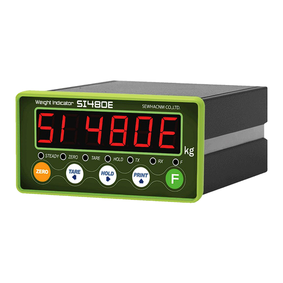
- Page 1 Digital Weighing Indicator SI 480E Instruction Manual 2014. 06. 25...
-
Page 2: Table Of Contents
CONTENTS 1. Before Installation ------------------------- 3 Page 2. Introduction ------------------------- 4 Page 3. Specification ------------------------- 5 Page 3-1. Specification ------------------------- 5 Page 3-2. Front Panel ------------------------- 6 Page 3-3. Rear Panel ------------------------- 8 Page 4. Installation ------------------------- 9 Page 4-1. Dimension & Cutting Size ------------------------- 9 Page 4-2. -
Page 3: Before Installation
This manual may be changed as the version is upgraded, without previous notice. Inquiries If you have any kinds of inquiries for this model, please contact your local agent or Head Office. Head Office : SEWHA CNM CO., LTD. Website : http://www.sewhacnm.co.kr Email : sales@sewhacnm.co.kr - 3 -... -
Page 4: Introduction
9. If the operation environment is dusty, regular cleaning might be needed. 2-3. Features 1. SI 480E model is the standard 1/8 DIN SIZE and compact enough, so it is easy to install. 2. It has wide range of DC Input. -
Page 5: Specification
3. SPECIFICATION 3-1 Specification Content Specification External Resolution 1/20,000 Internal Resolution 1/2,097,152 (±1,048,576) Input Sensitivity Min. 0.1µV/V Max Signal Input Voltage 3.0mV/V Load cell Excitation DC +5V A/D Conversion Method Performance Sigma-Delta Decimal Point 0, 0.0, 0.00, 0.000 10PPM/℃ 10PPM/℃ Drift 10PPM/℃... -
Page 6: Front Panel
3-2. Front Panel 3-2-1 Front Panel (Display / Key Pad) 3-2-2. State Lamp STEADY When the weight is “STEADY”, Lamp is ON. ZERO When the current weight is ”ZERO”, Lamp is ON. TARE “TARE” function is set, Lamp is ON. HOLD “HOLD”... - Page 7 1. To set the “HOLD” Function input : “HOLD”, 2 input : “HOLD Reset” ) 2.Calibration Mode , F-Function setting : Move to right 3. Under “SETUP” Mode, Enter into the “Calibration” Mode. 4. Go into test mode 1 5.Under HOLD setting first digit as “H” 1.
-
Page 8: Rear Panel
3-3 Rear Panel 1.POWER 2.INPUT 3. SERIAL I/F 4.LOAD CELL 1. Power DC IN: 24V (Power: 24V 1A recommended) 2. External Input terminal: Bottom side 2 port (Refer to F-233, 234 to select desired function of each input terminal) 3. Serial Interface terminal: Stand serial port is RS485 Communication Method Terminal Terminal... -
Page 9: Installation
4. INSTALLATION 4-1. External Dimension & Cutting Size External Dimension (unit: mm) 51480e Cutting Size (unit : mm) 4-2. Installation Components Connector (3EA) SI480E Pin terminal(15EA) User Manual 3P, 5P, 7P - 9 -... -
Page 10: Load Cell Installation
4-3 Load cell Installation Load Cell Wire Connection (In case of SEWHACNM’s Load cell) It depends on the manufacturer of load cell, please check the specification. -----Sewhacnm Co.,ltd. Load cell & wire color---- ※ Load cell wire color can be changed without prior notice. -
Page 11: Set Up
5. SET-UP 5-1. Set up This is the Menu which can set the all of the functions. There may be some display differences between real and on the manual. 5-1-1. Start “SET UP” Mode (Password is not used) 51480e 5et-Up When “SET UP”... - Page 12 To Go Each Mode Weight key during 4 seconds Pass word Calibration Calibration Simulation key during 4 seconds Pass word Calibration F-FUNCTION Mode key 4 times Analog Value key 4 times Test Mode1 Display key 4 times ...
- Page 13 ■ (Calibration) Adjusting “ZERO” Balance Adjust weight balance between “Real weight” on the load cell) and “Displayed weight of Indicator”. When you replace LOAD CELL or Indicator, you have to Calibration process once again. (When you start calibration mode, TARE, HOLD & PRINT will be reset.) Before processing calibration, please warm up the indicator during 15 min to guarantee more preciseness.
-
Page 14: Test Weight Calibration Mode
5-2 Test Weight Calibration Mode (Using test weight) 5-2-1. Start Test Weight Calibration Mode ---- On the screen “ “, input PASSWORD On pressing key for 4 seconds press On the screen “CALIBR“, press On the screen “SET.CAL” press Go into CALIBRATION MODE 5-2-2. - Page 15 5-2-3. “Decimal Point” and “Digit / Division” Value diui 0. 1 After “DIVI” is displayed, set Decimal point with key. Whenever you press key, the decimal point will be changed. And set Division value with key, finally press key to save the data. Max Decimal point will be 0.001, and digit can be selectable among 1, 2, 5, 10, 20, 50.
- Page 16 5-2-4. Measure the “DEAD” Weight of Weighing Scale. dead When “DEAD” is displayed, press key, then indicator will calculate Dead weight of scale part automatically. Cal-00 Indicator will search “DEAD weight” during 10~20 seconds to find the best condition. ※ To guarantee the preciseness, DEAD weight calculation (CAL00~CAL09) will be operated twice when resolution is less than 1/10,000.
- Page 17 When “UP” is displayed, load your test weight on the scale (weigh bridge) and press key. Ex) Load Cell CAPA : 20kg, division 0.001 Cal-10 Calculate Span value during 10 ~20 second, automatically. ※ To guarantee the preciseness, SPAN calculation (CAL00~CAL09) will be operated twice when resolution is less than 1/10,000.
-
Page 18: Simulating Calibration Mode
5-3. Simulation Calibration Mode(without Test weight) With this “Simulation Calibration Mode” you can make simple calibration without any “TEST weight” This calibration mode uses “Load cells’ max capacity” and “Max Output Rate(mV)”, so the weight adjustment degree might be less than “Test weight Calibration”. The guaranteed resolution of this “Simulation Calibration”... - Page 19 5-3-2. Setting “Capacity of Load Cell” Capa After “CAPA” is displayed, Check the max Capacity of your load cell. (Refer the label on the load cell, or test report.) Input the Max Capacity of Load cell. And press key. In case of multiple pieces of load cells are installed, make sum of each load cell’s capacity and make setting with max capacity.
- Page 20 5-3-4. Measure the “DEAD Weight” of Weighing Scale. dead When “DEAD” is displayed, press key with empty scale. The indicator starts to measure and find optimal “Dead weight value of Scale” automatically. Cal10 It takes 10 or 20 second to get the best situation.
- Page 21 If input wrong value, there will display “Err-01”, Setting “Capacity of Load Cell”. please go back to After recheck the label of load cell and retry the process. When “mV” is displayed, input Load cell Rated Output (mV), referring the load cell label. And press key to save.
-
Page 22: F-Function Setting
5-4. F-FUNCTION Setting Set-up means set the F-function and make optimal operation of SI 480E controller. ■ Starting F-FUNCTION Mode 5etUp kye 4 times Press Displaying “SETUP” press key. Make Function No. And Press Whenever press key, function No. increased. - Page 23 F-FUNCTION list(Summary) 5-4-1 F-list Subject Default Contents Equipment No. setting 01~99 00: Normal mode Weight–Back up Mode 01: Weight Back up Mode(Zero) 02: Weight Back up Mode(Zero&Tare) 00: Manual(Whenever “Print” key input) 01: Auto(At every steady states) 02: Auto(At the first steady states) Weighing Data Save Method 03: Auto(At weighing process finish) 04: Manual&...
- Page 24 00: Active within 2% of Max Capacity 01: Active within 5% of Max Capacity 02: Active within 10% of Max Capacity Zero key Operation Range 03: Active within 20% of Max Capacity 04: Active within 50% of Max Capacity 05: Active within 100% of Max Capacity 06: No limit 00: Active within 10% of Max Capacity 01: Active within 20% of Max Capacity...
- Page 25 00: Disuse 01: Zero 02: Tare 03: Tare removal 04: Tare/Tare removal External Input 1 Setting 05: Hold 06: Hold removal 07: Hold/Hold removal 08: Print 09: Subtotal Print 00: Disuse 01: Zero 02: Tare 03: Tare removal External Input 2 Setting 04: Tare/Tare removal 05: Hold 06: Hold removal...
- Page 26 00: Simplex / Stream Mode 01: Duplex / Command Mode Data transmission mode 02: Print Mode 03: Modbus(RTU) 00: Disuse “Check-Sum” under command mode 01: Use 00: Format 1 01: Format 2 Data Format under Stream Mode 02: Format 3 03: Format 4 00: Continuously 01: Single time on every steady state...
- Page 27 F-FUNCTION list(Detail) 5-4-2 (“●” Factory default) Equipment No. setting 01 ~ 99 ID No. setting with No. key. (01~99 selectable) Weighing Data Save Method selection Normal mode Weight Back up Mode(Zero) ● Weight Back up Mode(Zero&Tare) Weighing Data Save Method ●...
- Page 28 Steady Range During the set time period, estimate weighing part’s 01 ~ 99 “STEADY” condition and display. (Unit: 0.25 gradation) “STEADY” condition check time During the set time period, estimate weighing part’s “STEADY” condition and display. If you set small value, indicator will 01 ~ 99 take “STEADY”...
- Page 29 Tare Delay Time 00: Disuse 00 ~ 10 01 ~ 10: Use(Unit: 1 sec) Auto tare set when weighing starts ● Disuse Tare Removal Timing ● Manual Auto at empty range Auto at steady condition Auto Tare Removal Time Set time to tare removal 00 ~ 09 00: Disuse 01 ~ 09: Use (Unit : 1 sec)
- Page 30 External Input 1 Setting Disuse Hold ● Zero Hold/Hold removal Tare Hold/Hold removal Tare removal Print Tare/Tare removal Subtotal print External Input 2 Setting Disuse Hold Zero Hold/Hold removal Tare Hold/Hold removal Tare removal Print ● Subtotal print Tare/Tare removal Zero state lamp output standard ●...
- Page 31 Serial Communication Speed selection 2,400bps 4,800bps ● 9,600bps 14,400bps 19,200bps 28,800bps 38,400bps 57,600bps 76,800bps 115,200bps DATA transference Method selection ● Simplex Mode / Stream Mode Duplex Mode / Command Mode Print Mode MODBUS(RTU) Command mode “Check Sum” detection selection (F303-01) ●...
- Page 32 Print Format ● Continuous Print Single Print Print Output Delay Time 00 ~ 09 Unit: 1 sec Paper Withdraw Rate setting(After Continuous/Single Print) 00 ~ 09 Unit: 1 line add Paper Withdraw Rate setting(After SUB/GRAND Total Print) 00 ~ 09 Unit: 1 line add Grand total data delete ●...
- Page 33 5-4-3. Hidden Option How to enter Hidden function setting mode : Press Key during 4sec and input your password. Default password is (1111). Press key after input your password. Then show “SET.CAL” on the screen press “ ” key. F-LIST Subject Default Contents...
- Page 34 5-5. Test Mode Before starting the TEST mode, please remove operating devices. 5etUp Press key 4 times On the screen “SETUP” Test mode 1: Press ● Test mode 2: Press ● Cancel / Go back: Press key. ● TEST MODE 1 Analog Display ESC / BACK...
- Page 35 5-5-1. Analog Deviation Check Mode You can check the deviation of analog value. Display current Display from Display from analog value to ‘0’ 1 million unit ten million unit 5-5-2. Display check mode Test FND and LED Blink FND and LED by 1 Segment gradually. 5-5-3.
- Page 36 5-5-5. Standard Serial Interface Test Mode. C0rn1 Connect with PC or other devices through serial interface and check the transference and receipt. At the normal operation, display will be blinked. ※ TESTING PROTOCOL. Format: STX Id No. TEST ETX You cannot test Standard and Extended Serial Interface at the same time. ※...
- Page 37 INTERFACE 6-1-1. Serial Interface (RS – 485: Standard installed, Selectable) 5 1 4 8 0 e 5 1 4 8 0 e 5 1 4 8 0 e 32 pcs of Indicators are connectable. 6-1-2. Serial Interface (RS – 422: Standard, Selectable) 5 1 4 8 0 e 5 1 4 8 0 e 5 1 4 8 0 e...
- Page 38 6-1-3. Serial Interface (RS – 232 order spec) 5 1 4 8 0 e GND(T+) Serial communication interface is sensitive to electric noise. Install isolated place from Power cable or other electric cables and wires, and please use shielded cable for better performance. 6-1-4.
- Page 39 2.Format 2: ID Number + Data Transference (Refer F305-01 / 22 byte) Header1 Header2 OL : OVER LOAD NT : NET-WEIGHT(Tare is not set) ST : STEADY GS : when setting TARE US : UNSTEADY 3. Format 3: ID Number + State (Refer F305-02 / 17 byte) Header1 Header2 O : OVER...
- Page 40 6-1-5. Command Mode Under “Command Mode”, Indicator will recognize the receipt of Order based on 02h(STX) and 03h(ETX) signal, and transfers 06h(ACK), 15h(NAK). Error Code (Function 304 - 01 or 311 - 01) 0 (30h) Normality 3 (33h) Number data Error 1 (31h) Check-Sum Error Excess of write data’s allowable...
- Page 41 6-1-8. Read Command Detail Current Weight ASCII : STX ID(2byte) RCWT ETX HEX : 02 30 31 52 43 57 54 03 STX ID RCWT State1(1byte) State2(1byte) P decimal point(1byte) +/- (1byte) Current weight(7byte) Weight unit(2byte) ETX Response State1 : O(Over Load) , S(Steady), U(Unsteady) State2 : N(Net weight), G(Gross weight) Ex) Steady(S), TARE not used(N), 0.000kg Indicator memory data...
- Page 42 Grand Total data ASCII : STX ID(2byte) RGRD ETX HEX : 02 30 31 52 47 52 44 03 STX ID RGRD P decimal point(1byte) the no. of weighing (6byte) Response Accumulated weight(10byte) unit(2byte) ETX Ex) the no. of weighing : 10 , Accumulated Weight : 10.000kg Current Time data ASCII : STX ID(2byte) RTIM ETX HEX : 02 30 31 52 54 49 4D 03...
- Page 43 6-1-9. Write Command Detail Zero (same as “ZERO” key) ASCII : STX ID(2byte) WZER ETX HEX : 02 30 31 57 5A 45 52 03 Response Normal : STX ID ACK ETX Error : STX ID NAK ETX TARE ASCII : STX ID(2byte) WTAR ETX HEX : 02 30 31 57 54 41 52 03 Response Normal : STX ID ACK ETX Error : STX ID NAK ETX...
- Page 44 Time Setting ASCII : STX ID(2byte) WTIM time(6byte) ETX 예)12:00:00 Response Normal : STX ID ACK ETX Error : STX ID NAK ETX How to Calculate Check sum Sum the value from “STX” to “ETX” and converts to ASCII(2byte) and transfer. Convert the Sum value(HEX) to ASCII and transmit(28byte) .
- Page 45 6-1-10. Modbus Memory Map - RO : Read Only - RW : Read Write - Each P/N’s set point can’t over max capacity of Indicator. ex)35.00kg = 3,500 (0xDAC) - When you input date and time, it should be 6digit. ex) 1 January 2014 = 140101 (0x22345) 15(H) : 50(M) : 17(S) = 155017 (0x25D89)
- Page 46 6-1-11. Modbus memory register (1) Digital input register (Address : 17, Length : 2) INPUT1 INPUT2 INPUT3 INPUT4 (2) Lamp register (Address : 19, Length : 2) Steady Zero Tare OUT1 OUT2 OUT3 OUT4 Hold (3) Error register (Address : 21, Length : 2) Load cell Over Set point...
- Page 47 SI 480E DIN SIZE WEIGHING CONTROLER 6-2 Serial Print (F303 or F310-02 setting) – RS-232 Serial Interface. It can be connected with all kinds of Serial interface printer, but the printing format is already programmed and fixed with SE7200/7300 model.
- Page 48 SI 480E DIN SIZE WEIGHING CONTROLER 7. Error & Treatment 7-1. Load Cell Installation Error Cause Treatment Remarks 1) Load cell broken 1. Input Resistance of “EXC+” and “EXC-“ is about 2) Load cell isolation 1) Measure input/output 400Ω ±30 resistance error resistance of Load cell.
- Page 49 SI 480E DIN SIZE WEIGHING CONTROLER 7-2. Calibration Process Display Cause Treatment Re-input the Max Capacity, less than 20.00 When Max capacity/digit value is over 20,000 (Max Capacity / Digit) Re-input Standard weight value with Number keys, Standard weight value is over than Max Capacity ...
- Page 50 SI 480E DIN SIZE WEIGHING CONTROLER 7-3. Digital Weighing Indicator Display Cause Treatment 1. Under “TEST” mode 1, check analogue value. If you cannot get any analogue value 1. Load cell Error or there is no change although adding 2. Load cell cable Error load, please check load cell, load cell cable, “”...
- Page 51 SI 480E DIN SIZE WEIGHING CONTROLER WARRANTEE CETIFICATION This product is passed SEWHACNM strict quality test. If there is defect of manufacturing or abnormal detection within warrantee period, please contact our Agent or Distributor with this Warrantee certificate. Then, we will repair or replace free of charge.
Need help?
Do you have a question about the SI 480E and is the answer not in the manual?
Questions and answers