Table of Contents
Advertisement
Advertisement
Table of Contents

Subscribe to Our Youtube Channel
Related Manuals for Sewhacnm SI 4010R


Summary of Contents for Sewhacnm SI 4010R
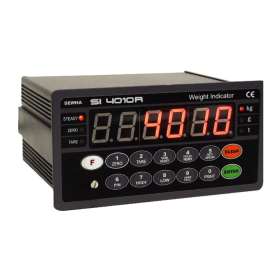
- Page 1 Digital Weighing Indicator SI 4010R Instruction Manual Version 3.17 (Apr. 2011)
-
Page 2: Table Of Contents
DIGITAL WEIGHING INDICATOR SI 4010R CONTENTS 1. Before Installation --------------- 3 page 2. Introduction --------------- 4 page 3. Specification -------------- 5 page --------------- 4. Installation 10 page 4-1. External Dimension & Cutting Size --------------- 10 page 4.2 Installation Components --------------- 10 page 4-2. -
Page 3: Before Installation
1-3. Copy Rights 1) All Right and Authority for this Manual is belonged to Sewhacnm Co.,Ltd. 2) Any kinds of copy or distribution without Sewhacnm Co.,Ltd’s permission will be prohibited. 1-4. Inquiries If you have any kinds of inquiries for this model, please contact with your local agent or Head Office. -
Page 4: Introduction
2-1. Introduction Thank you for your choice, this “SI 4010R” Industrial Digital Weighing Indictor.. This “SI 4010R” model is simple Comparison and Filling Application usage Digital Weighing Indicator, with powerful communication performance. With 2ports serial port communication and High Speed A/D conversion performance will lead you to precise weighing process. -
Page 5: Specification
DIGITAL WEIGHING INDICATOR SI 4010R 3. SPECIFICATION 3-1. Analog Input & A/D Conversion Input Sensitivity 0.3㎶ / Digit DC 10V ( - 5V ~ + 5V ) Load Cell Excitation Max. Signal Input Voltage Max.32mV [Zero] ±16PPM/℃ Temperature Coefficient [Span] ±3.5PPM/℃... - Page 6 DIGITAL WEIGHING INDICATOR SI 4010R 3-4. Option Card ※ Serial Interface (RS-232C) or Current Loop is Standard installed. In the Optional Serial port, there is no Current Loop function. Option No.1 Printer Interface : Centronics Parallel Analog Output (0~10V or 0~5V) Option No.2...
- Page 7 DIGITAL WEIGHING INDICATOR SI 4010R 3-5-2. Key Operation Make Weight value as Zero. Under F08, you can set the Zero key operation range, as 2%, or 5%, or 10%, or 20% of Max. Capacity. ※ Under “Tare” key input, Zero key will not be activate within operation range.
- Page 8 DIGITAL WEIGHING INDICATOR SI 4010R 1. Manual Print Whenever press this key, you can print out. 2. Calibration mode - Digit setting Whenever pressing “0”key, digit will be change 1, 2, 5, 10, and 50. - Decimal point position Whenever pressing “0”key, decimal point will be change.
- Page 9 DIGITAL WEIGHING INDICATOR SI 4010R 3-6. Rear Panel ②Option Card 1 ③ Option Card 2 ⑥ External Input ⑤ SERIAL I/F ① POWER AC IN ④ LOAD CELL Connector ① POWER AC IN - Power switch : Power on/off switch.
-
Page 10: Installation
DIGITAL WEIGHING INDICATOR SI 4010R 4. INSTALLATION 4-1. External Dimension & Cutting Size (External Dimension) (unit : mm) 4-2. Installation Components Communication Connector Power Cable Load-cell Cable (D-SUB 9P) -
Page 11: Load Cell Installation
DIGITAL WEIGHING INDICATOR SI 4010R 4-3. Load Cell Installation 4-3-1. Load Cell Connector Specification RED(EXC+) WHITE(EXC-) GREEN(SIG+) BLUE(SIG-) YELLOW(SHLD) 4-3-2. Load Cell Installation 1) You can connect Max. 8pcs of same capacity Load cells at once. (350Ω) 2) You have to make horizontal balance on the ground. - Page 12 SI 4010R 4-3-3. Formula to plan the precise weighing system This “SI 4010R” weighing controller’s Max. input sensitivity is 0.2㎶ / Digit. And for precise weighing system, the following formula must be satisfied. Caution : “Input sensitivity” means Min. output voltage variation of weighing part to change 1digit. So, Cautions please do not make large input voltage to make reliable weighing system.
-
Page 13: Set-Up
DIGITAL WEIGHING INDICATOR SI 4010R 5. SET-UP 5-1. Calibration Adjust weight balance between “Real weight” on the load cell(Weight Part) and “Displayed weight of Indicator”. When you replace LOAD CELL or Indicator, you have to do Calibration process once again 5-2. - Page 14 DIGITAL WEIGHING INDICATOR SI 4010R p 20. 0 00 6. Press key to save and move to next step. 7. Define the optimal Digit/Division value of weighing measurement. Whenever pressing key, the Digit/Division value will be changed like “1 2 5 10 20 50” .
- Page 15 DIGITAL WEIGHING INDICATOR SI 4010R Ex) Load Cell CAPA : 20kg, division 0.001 l 2. 0 00 Use test weight(at least 2kg) which is 10% of max CAPA(20kg) input test weight 2.000 13. After displaying “UP” ,please load “Test Weight” .
-
Page 16: Simulation Calibration Mode(Without Test Weight)
DIGITAL WEIGHING INDICATOR SI 4010R 5-3. Simulation Calibration Mode (Calibrate without Test weight) Through this “Simulation Calibration Mode” you can make simple calibration without Test weight. This calibration mode uses “Load cells’ max. capacity” and “Max. Output Rate(mV)”, the weight adjustment degree might be less than “Test weight Calibration”. - Page 17 DIGITAL WEIGHING INDICATOR SI 4010R 6. Define the optimal position or decimal point p 15. 0 0 Whenever pressing key, Decimal point will be changed. p 15. 0 0 7. Press key to save Digit /Decimal point and move to next step.
- Page 18 DIGITAL WEIGHING INDICATOR SI 4010R Cell0Ut 12. At this step input Max. Output rate(mV) of load cell. o1. 4 5800 13. Input Load cell Output Rate(mV/V) (refer the load cell label) Ex)Load cell Related output : 1.458 mV/V ※ Caution : Due to some variation between “State output rate” and “Real Output rate” of load cell, there might be some weight difference after finishing calibration.
-
Page 19: Set-Up
DIGITAL WEIGHING INDICATOR SI 4010R 5-4. Set-up Set-up means set the F-function and make SI 4000 weighing controller will perform more accuracy. (Considering external / internal environmental condition) ※remarks : In case that “P-W” is displayed, you have input the pass word to start calibration mode. - Page 20 DIGITAL WEIGHING INDICATOR SI 4010R 5-5. F-Function Detailed information ■ General Function Setting (“●” Factory default set value) Weight-Back up selection ● Normal Mode Weight Back up Mode Motion Band Range setting This is set “Steady” acceptable range of weighing part.
- Page 21 DIGITAL WEIGHING INDICATOR SI 4010R Tare key Operation Range selection Activated within 10% of Max. Capacity Activated within 20% of Max. Capacity ● Activated within 50% of Max. Capacity Activated within 100% of Max. Capacity “Hold” Mode selection ● Peak Hold : Measure Max. weight value and hold on display.
- Page 22 DIGITAL WEIGHING INDICATOR SI 4010R Auto TARE Reset time setting Automatic “TARE” reset time setting. ∫ 00 : not use 30 : after 3.0sec, Tare will be reset. Auto Print Delay time setting Auto Print Delay time setting. ∫ 00 : There is no Delay 30 : After 3.0sec auto print out., when the weight is steady over than Empty range.
- Page 23 DIGITAL WEIGHING INDICATOR SI 4010R ◆ Weighing Mode 1. Limit Mode – Simple Comparison Weight HIGH Near Zero TARE(IN) Output 1 Output 2 HIGH Output 3 Empty Weighing Mode HIGH EMPTY When the Weight When the Weight When the Weight is less Limit Mode 1.
- Page 24 DIGITAL WEIGHING INDICATOR SI 4010R ◆ Weighing Mode 2. Limit Mode – Reverse Simple Comparison Weight HIGH Near Zero TARE(IN) Output 1 Output 2 HIGH Output 3 Empty Weighing Mode HIGH EMPTY When the Weight When the Weight When the Weight is less Limit Mode 2.
- Page 25 DIGITAL WEIGHING INDICATOR SI 4010R ◆ Weighing Mode 3. Limit Mode Weight HIGH Near Zero TARE(IN) Output 1 Output 2 HIGH Output 3 Empty Weighing Mode HIGH EMPTY When the Weight When the Weight reaches to set value When the Weight is Relay will be “ON”...
- Page 26 DIGITAL WEIGHING INDICATOR SI 4010R ■ Communication Mode setting (Serial Port 1. - Standard installed port) Parity Bit selection Mode ● No Parity Odd Parity Even Parity Serial Communication Speed selection 2,400bps 4,800bps ● 9,600bps 14,400bps 19,200bps 28,800bps 38,400bps 57,600bps...
- Page 27 DIGITAL WEIGHING INDICATOR SI 4010R Mode selection (Under F32-00, F35-01 setting, only) ● Manual Print : Whenever “Print” key input. Auto Print : When the Weight is steady over “LOW” set value. Transferred Weight DATA Byte selection ● 7 Byte data Transfer 8 Byte data Transfer ■...
- Page 28 DIGITAL WEIGHING INDICATOR SI 4010R Printing Language Selection (If you install on Standard Serial Port) ● KOREAN ENGLISH Minus(-) symbol Print selection ● Print minus(-) symbol, if the weight is minus(-). Ignore minus(-) symbol Function / Clear key Activation display selection ●...
- Page 29 DIGITAL WEIGHING INDICATOR SI 4010R ■ Other Setting EMPTY Range setting You can set “EMPTY” Range. Within set range, indicator will not display current weight and just display “Zero”. X.X.X.X.X.X. “0.000” setting : When Net Zero, “Zero” status lamp and Near Zero relay will be output.
- Page 30 DIGITAL WEIGHING INDICATOR SI 4010R ■ Communication Mode setting (Serial Port 2. - Optional Serial port) This setting will be activated only when “Optional Serial Port” is installed. Parity Bit selection Mode ● No Parity Odd Parity Even Parity Serial Communication Speed selection...
-
Page 31: Interface
DIGITAL WEIGHING INDICATOR SI 4010R 6. INTERFACE 6-1. Serial Interface (RS-232C) RS-232C Serial Interface is sensitive/weak for electric Noise. So, please isolate with AC power cable and use shield cable to reduce the electric noise effect. 6-1-1. Communication with PC(Personal Computer) or Other devices... - Page 32 DIGITAL WEIGHING INDICATOR SI 4010R Parity Stop Data Byte – Refer “F40” Start Bit 6-1-4 Data Format(1) : ID Number will not be transferred. (Refer “F-function 37-0”) Including Decimal point Header 1. Header 2. Data Byte ( 7 or 8 byte )
- Page 33 DIGITAL WEIGHING INDICATOR SI 4010R ① Header 1. : OL : Over Load, Under Load ST : Display “Steady” US : Display “Un-Steady” ② Header 2. : NT : Net-Weight GS : Net-Weight, under TARE. ③ Data Bit(Number) 2B(H) : “+” Plus 2D(H) : “-“...
- Page 34 DIGITAL WEIGHING INDICATOR SI 4010R 6-1-7. Data Format : AD – 4321 Data Transference) – AD – 4321 18byte Format(F37-03) +,- / Including Decimal point 8byte WeightU Header 1 Header 2 Data(8) ① Header 1. : OL : Over Load, Under Load ST : Display “Steady”...
-
Page 35: Current Loop Interface
DIGITAL WEIGHING INDICATOR SI 4010R 6-2. Current Loop Interface “Current Loop” Interface is stronger for Electric Noise than “RS-232C” interface. So, it can be used for long distance communication.(About 100m long distance). ※ Current Loop Interface supports, up to 9,600 Communication Speed, only. -
Page 36: Print Interface (Option 01 : Centronics Parallel Interface)
DIGITAL WEIGHING INDICATOR SI 4010R 6-3. Print Interface (Option 01 : Centronics Parallel Interface) This Print Interface Option is based on “Centronics Parallel Interface”, so this print interface can be connected other printers using this communication method. But, the print format is programmed based on our “SE7300”, and “SE7320” Industrial Printers, so you had better to use these printer for convenience. - Page 37 DIGITAL WEIGHING INDICATOR SI 4010R 6-3-5. Print Format < 42 Column only > Single Print Format Continuous Print Format Date : 2008-05-10 Date : 2008-05-10 Time : 14:38:33 Time : 14:38:33 Code S/N Weight Code S/N Weight 000001 1.000kg 000001 1.000kg...
-
Page 38: Analog Output Interface (Option 02 : 0~10V)
DIGITAL WEIGHING INDICATOR SI 4010R 6-.4 Analog Output Interface (Option 02 : 0~10V Output) This Option card converts weight value to Analog Voltage output(0~10V) and transfers to external devices(Recorder, P.L.C), controlled by voltage output. 6-4-1. Specification ① Output Voltage : 0~10V DC output ②... -
Page 39: Analog Output Interface (Option 03 : 4~20Ma)
DIGITAL WEIGHING INDICATOR SI 4010R 6-5. Analog Output Interface (Option 03 : 4~20mA Output) This Option card converts weight value to Analog Electric Current output(4~20mA) and transfers to external devices(Recorder, P.L.C), controlled by electric current output. 6-5-1. Specification Output Current... -
Page 40: Serial Interface (Option 04 : Rs-232C/422/485)
DIGITAL WEIGHING INDICATOR SI 4010R 6-6. Serial Interface (option 04 : RS-232C/422/485) RS-422/485 serial interface is more stable for electric noise effect compare with other communication method, using electric current difference. But, install isolated place from Power cable or other electric cables and wires, and please use shielded cable for better performance. - Page 41 DIGITAL WEIGHING INDICATOR SI 4010R 6-7. BCD Input ( Option 05) – Input for Part No. selection. This “BCD interface” option card can be applied on PLC (Programmable Logic Controller), or Score Board applications. Each Input circuit is isolated with “Photo-Coupler”, from external devices electrically.
-
Page 42: Bcd Output(Option 06)
DIGITAL WEIGHING INDICATOR SI 4010R 6-8. BCD Output Interface( Option 06) This “BCD interface” option card can be applied on PLC (Programmable Logic Controller), or Score Board applications. (NPN TYPE) Each Input circuit is isolated with “Photo-Coupler”, from external devices electrically. -
Page 43: Command Mode
DIGITAL WEIGHING INDICATOR SI 4010R 6-9. Command Mode 6-9-1. Read Command (Standard Serial Port and Optional Port is same.) Current weight ASCII : STX ID(2Byte) RCWT ETX HEX : 02 30 31 52 43 57 54 03 (ID No.: 01) STX ID NO. - Page 44 DIGITAL WEIGHING INDICATOR SI 4010R SI4010R REPONSE STX IN NO. RWRS Weight(7/8byte), Ex input(4byte), Output(3byte) ETX P/N Data ASCII : STX ID(2Byte) RPNO ETX HEX : 02 30 31 52 50 4E 4F 03 (ID No. : 01 ) SI4010R REPONSE STX IN NO.
-
Page 45: Error & Treatment
DIGITAL WEIGHING INDICATOR SI 4010R 7. Error & Treatment 7-1. Load Cell Installation Error Cause Treatment Remark 1.Input Resistance of 1.Load cell broken 1. Measure “EX+” and “EX-“ is 2. Load cell isolation input/output resistance about 350Ω~450Ω. resistance error of Load cell. - Page 46 DIGITAL WEIGHING INDICATOR SI 4010R 7-3. Digital Weighing Indicator Error Display Cause Treatment 1. Under “TEST” mode 1, check analogue value. If you can not get any analogue value 1. Load cell Error or there is no change although adding load, “CELL-...
-
Page 47: Indicator Test Mode
DIGITAL WEIGHING INDICATOR SI 4010R 7-4. Indicator Test mode Through this “Test Mode”, you can check basic conditions of Indicator. This Test consist with total 7 tests. 7-4-1. Enter “Test Mode” key for 4sec, then display will show “F-Test”. Press Under this display, press No.2 key and enter the “Test Mode”. - Page 48 2. Warrantee Exception Clause - Warrantee period is expired. - Any kinds of Mal-function or defection caused by Modification or Repair without Sewhacnm’s permission. - Any kinds of Mal-function, Defection, or External damage, caused by operator - Any kinds of Mal-function, Defection, caused by using spare part from Non-Authorized Distributor or Agent.
Need help?
Do you have a question about the SI 4010R and is the answer not in the manual?
Questions and answers