Table of Contents
Advertisement
Quick Links
2015 © Gibson Innovations Limited.
All rights reserved.
This product has been manufactured by, and is sold
under the responsibility of Gibson Innovations Ltd., and
Gibson Innovations Ltd. is the warrantor in relation to
this product.
Philips and the Philips Shield Emblem are registered
trademarks of Koninklijke Philips N.V. and are used
under license from Koninklijke Philips N.V.
A
B
H
C
D
I
E
F
J
G
5
6
8
sqm7842_27_2L_um_150730.indd
1-3
Register your product and get support at
www.philips.com/support
User manual
Manual del usuario
UM_SQM7842
27_EN_V1.0
WK15314
1
2
4
3
7
*
9
E n gl i sh
1 Important safety instructions
SQM7842
Caution
•
Read these instructions before you begin. If you are unsure of any
part of the process, contact a professional contractor or installer
for assistance. Improper installation can result in injury or damage.
•
The wall or mounting surface must be capable of supporting
the combined weight of the mount and the display; if not, the
structure must be reinforced.
•
Locate pipes, wires, or any other hazards in the wall where you
wish to install the mount before drilling.
•
Safety gear and proper tools must be used. Failure to do so can
result in injury or damage.
•
Two people are recommended for installation. Do not attempt to
lift a heavy display without assistance.
•
Follow all instructions and recommendations regarding adequate
ventilation and suitable locations for mounting your display.
Consult the owner's manual for your particular display for more
information.
•
This wall mount is intended for use only with the maximum
weight of 45 kg (100 lbs). Use with heavier than the maximum
weights indicated may result in instability causing possible injury.
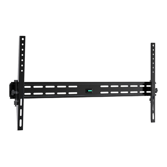
2 Tilt wall mount (for LCD, Plasma, and LED displays)
What's in the box
Wall plate (x1)
Mount arm (x2)
User manual (x1)
Hardware kit (x1)
Hardward kit
M8 x 63 lag bolt (x4)
A
Lag bolt washer (x4)
B
Concrete anchor (x4)
C
M6 x 12 screw (x4)
D
M6 x 30 screw (x4)
E
Tools required
•
Phillips head screw driver
•
Ratchet or driver with 13 mm (1/2") socket
•
Electric or portable drill
•
6 mm (1/4") drill bit and stud finder for drywall installation
•
10 mm (3/8") Masonry bit for concrete installation
3 Installation
Mount to the drywall
Caution
For safety reasons, this mount must be secured to at least two
wood studs no less than 16" apart. The studs must be capable of
supporting the combined weight of the mount and display.
1 Use a high quality stud finder to locate two adjacent
studs where you wish to install your mount. Mark both
edges of each stud to help identify the exact center.
Note
You must use the center of each stud to avoid cracking or splitting
the wood during installation.
2 Place the wall plate against the wall and level it using the
*
integrated bubble level.
3 While another person holds the wall plate in position,
mark four locations (two per stud) for securing the
mount to the wall (see Fig. 1).
4 Set the wall plate aside and drill a 6 mm (1/4") pilot hole
at each marked location.
5 Place the wall plate back against the wall and attach it
using the lag bolts
(see Fig. 2). Do not over-tighten these bolts and do not
release the wall plate until all bolts are in place. Ensure
that the wall plate remains level after all bolts are secured.
Mount to the concrete wall
Caution
For safety reasons, the concrete wall must be capable of
supporting the combined weight of the mount and the display. The
manufacturer takes no responsibility for failure caused by walls of
insufficient strength.
1 Place the wall plate against the wall in the desired
location and level it using the integrated bubble level.
2 While another person holds the wall plate in place, mark
four evenly spaced locations on the wall for securing the
mount (see Fig. 3).
3 Set the wall plate aside and drill a 10 mm (3/8") hole at
each marked location. Remove any excess dust from the
holes.
4 Insert a concrete anchor
flush with the concrete surface (see Fig. 4). A hammer can
be used to lightly tap the anchors into place if necessary.
M8 x 12 screw (x4)
F
M8 x 30 screw (x4)
G
M6 washer (x4)
H
M8 washer (x4)
I
Spacer (x8)
J
and lag bolt washers
provided
A
B
into each hole so that it is
C
30/07/2015
18:00:58
Advertisement
Table of Contents

Subscribe to Our Youtube Channel
Related Manuals for Philips SQM7842


Summary of Contents for Philips SQM7842
-
Page 1: Important Safety Instructions
Gibson Innovations Ltd., and Wall plate (x1) Gibson Innovations Ltd. is the warrantor in relation to this product. Mount arm (x2) Philips and the Philips Shield Emblem are registered UM_SQM7842 User manual (x1) trademarks of Koninklijke Philips N.V. and are used 27_EN_V1.0 under license from Koninklijke Philips N.V. - Page 2 ubicación marcada. Elimine el exceso de polvo de los orificios. Note E sp a ñ o l 4 Introduzca un taco para hormigón en cada orificio hasta que estén a ras de la superficie de hormigón (consulte la If the concrete wall is covered by a layer of plaster or drywall, the 1 Instrucciones de seguridad importantes imagen 4).
Need help?
Do you have a question about the SQM7842 and is the answer not in the manual?
Questions and answers