Advertisement
Quick Links
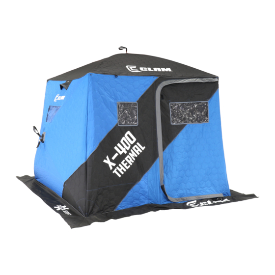
SPECIFICATIONS
▪
Part Numbers: 110127
▪
Set Up Size: (L 188" x W 77" x H 82")
▪
Packed Size: (L 75" x W 48" x H 20")
▪
W e i g h t: 170 lbs.
▪
Instructions Document No: 104933-B
Please contact customer service directly at the E-mail or phone number listed below for any
quality issues. ONCE USED THIS PRODUCT CANNOT BE RETURNED TO STORE.
** Warranty cannot be honored without an original, dated receipt **
** REGISTER YOUR PURCHASE ONLINE AT CLAMOUTDOORS.COM **
IMPORTANT-PLEASE READ:
This product is warranted to the original retail purchaser (from an authorized dealer) and is non-transferable.
Clam Outdoors has a three year manufacturer's defect warranty from the date of original purchase. Warranty
does not cover cracked or worn bases (if runner kits have not been installed as recommended), cracked
windows, tent tears or cuts, or broken or bent hoops due to high wind weather conditions or unattended use.
Defective parts will be replaced or repaired (at the manufacturer's option) if found to be defective within three
year from the date of original purchase. Warranty will be void if product has been subject to neglect, misuse,
improper installation, misapplication, alteration, accident including but not limited to improper maintenance, or use
of unauthorized parts or attachments. Please read the entire owner's manual to ensure proper installation, use,
storage and care of your Clam Shelter.
To submit a warranty claim request, please use one of the following methods:
Customer Service Hrs: 9am to 4pm, Monday – Friday Central Standard Time
Clam Outdoors, Inc.
Attn: Customer Service – Warranty Department
12135 Brockton Lane
Rogers, MN 55369
Phone: 763-231-4120
Fax: 763-231-4121
Email:
customerservice@clamcorp.com
Website:
Clamoutdoors.com
In your request, please include your full name, address, phone number, a copy of your receipt, a brief description
of the problem, and pictures to clearly show the area(s) of concern. Our Warranty Department will review your
request, and a Clam representative will contact you regarding your claim status. All returns must be shipped to us
postage pre-prepaid.
It is expressly understood that Clam Outdoors Inc., liability for its products, whether due to breach of
warranty, negligence, strict liability, or otherwise, is limited to the repair of the product as stated above. Clam is not
liable for any injury, loss, damage, or expense, whether direct or consequential, including but not limited to loss of
use, income, profit, or damage to material arising in connection with the sale, installation, use of, inability to use,
or the repair or replacement of Clam products. Clam reserves the right to make alterations or modifications in
its products at any time, which in its opinion, may improve the performance and efficiency of the product. Clam
shall not be obligated to make such alterations or modifications to products already in service.
STEP 6
WARRANTY INFORMATION
LIMITATION OF LIABILITY
MODELS 10127
Advertisement

Related Manuals for Clam THERMAL X 400


Summary of Contents for Clam THERMAL X 400
- Page 1 It is expressly understood that Clam Outdoors Inc., liability for its products, whether due to breach of warranty, negligence, strict liability, or otherwise, is limited to the repair of the product as stated above. Clam is not liable for any injury, loss, damage, or expense, whether direct or consequential, including but not limited to loss of use, income, profit, or damage to material arising in connection with the sale, installation, use of, inability to use, or the repair or replacement of Clam products.
-
Page 2: Parts List
STEP 6 PARTS LIST QTY. PART NO. DESCRIPTION 104904 BASE, X400 104892 TUBE, HOOP, X200/X400 104897 TUBE, HALF HOOP, X200/X400 109560 LIGHT STICK LARGE 104906 TENT, X400 THERMAL 104922 KIT, SPRDR POLES, X400 (INCLUDES THE FOLLOWING) 104913 ASSY, SPREADER, ROOF, .88 X 40 104915 ASSY, SPRDR, PORCH, X200/X400 101399... - Page 3 STEP 6 HARDWARE FASTENERS REFERENCE...
-
Page 4: Required Tools
STEP 6 REQUIRED TOOLS #2 AND #3 PHILLIPS HAND SCREW 3/8 AND 7/16 COMBINATION WRENCH OR SOCKETS #2 PHILLIPS SCREW BIT 3/8 DRILL BIT POWER DRILL... - Page 5 STEP 6 *USING A DROP OF OIL ON ALL NUTS WILL EASE THE ASSEMBLY PROCESS. *IT IS BEST TO USE THE AID OF ANOTHER PERSON DURING ASSEMBLY. STEP 1 INSTALL ANY RUNNER KIT OPTIONS BEFORE ASSEMBLING SHELTER. REFER TO RUNNER KIT INSTRUCTIONS 1.
- Page 6 STEP 3 STEP 6 CHOOSE WHICH LOCATION YOU PREFER TO HAVE BATTERY LOCATED. LIGHT POLE WIRE WILL NEED TO BE ABLE TO REACH BATTERY. 1. INSTALL BATTERY BRACKET, ASSEMBLY (108829) AS SHOWN USING 3/8” DRILL BIT OR REFER TO INSTALLATION MANUAL THAT IS INCLUDED WITH KIT STEP 4 1.
- Page 7 STEP 5 STEP 6 1. ASSEMBLE LIGHT STICK, 109560, TO HALF POLES, 104897, AS SHOWN. DO NOT CUT ANY OF YOUR POLES 104897 STEP 6 2. ASSEMBLE REMAINING POLES AS SHOWN 104892...
- Page 8 STEP 6 STEP 7 1. INSTALL HOOP POLES OVER POLES AND SUPPORTING SPREADER POLES AS SHOWN 2. INSERT(101249) ROPE ENDS THRU HOLES IN FRONT OF BASE AND KNOT EACH END. LIGHT STICK (109560) WIRE TO BE POSITIONED TO SAME SIDE AS BATTERY HOLDER!! LIGHT STICK WIRE DO NOT INSTALL FRONT LIGHT STICK WIRE...
- Page 9 STEP 8 STEP 6 ROTATE THE SWIVEL (101399) 45 DEGREES TO AID IN THE INSTALLATON PROCESS AS SHOWN. 1. ASSEMBLY AS SHOWN AND SECURELY TIGHTEN. SAME BLOCK STYLES MUST BE ALIGNED TO EACH OTHER STEP 9 1. INSTALL THE ASSEMBLY FROM STEP 7 TO SEAT AS SHOWN AND SECURELY TIGHTEN...
- Page 10 STEP 10 STEP 6 1. INSTALL SEAT COVERS OVER SEAT AS SHOWN USING VELCRO STRAPS TO FASTEN IN PLACE STEP 11 1. ASSEMBLE THIS END OF THE SEAT ASSEMBLY AS SHOWN AND SECURELY TIGHTEN.. 104905 ASSEMBLED VIEW...
- Page 11 STEP 12 STEP 6 1. SLIDE THE ASSEMBLY FROM PREVIOUS STEP THRU SEAT BLOCKS AS SHOWN. STEP 7 STEP 13 1. ASSEMBLE THIS END OF THE SEAT ASSEMBLY AS SHOWN AND SECURLEY TIGHTEN 104905 COMPLETED SEAT ASSEMBLY ASSEMBLED VIEW...
- Page 12 STEP 14 STEP 6 1. SLIDE FRONT OF SEAT ASSEMBLY INTO OUTER FLANGE OF BASE AND DROP BACK SIDE INTO PLACE. THEN SNAP (102512) LATCH INTO POSITION TO SECURE SEAT ASSEMBLY AS SHOWN STEP 15 1. DRAPE THE TENT, PN 104906 OVER THE HOOP POLES. ATTACH THE TENT TO THE POLES ON THE INSIDE WITH THE VELCRO STRAPS.
- Page 13 FOLDING SEQUENCE IMPORTANT!! WHEN COLLAPSING THE X400 SHELTER IT IS VERY IMPORTANT TO COLLAPSE THE FRONT HOOP POLES FIRST TO RELIEVE THE TENSION ON THE TENT WHEN FOLDING. FAILURE TO COLLAPSE THE FRONT POLES FIRST MAY CAUSE THE TENT TO TEAR AT THE CORNERS AND WILL NOT BE COVERED UNDER WARRANTY...
-
Page 14: Safety Instructions
(NOTE: Pulling behind an ATV or snowmobile may result in premature wear of the base). ▪ In windy conditions it is advised to secure your shelter to the ice using Clam’s Ice Anchor Kit (PN 108064) and Ice Anchor Installation Tool (PN 108348). -
Page 15: Frequently Asked Questions
Q: What will help keep mice or rodents from eating the tent of my Clam or Fish Trap? A: We recommend that you keep your tent in a sealed plastic tote with laundry dryer sheets or moth balls. If the shelter is stored in a barn or shed take the tent off the house and store it in a rodent-free environment such as in your home. - Page 16 We are only set up to ship warranty or replacement parts required to MAINTAIN a Clam shelter (tents, poles, parts, patch kits, etc.). No accessories – see a local dealer or an online dealer of Clam products. If the replacement parts are not under warranty you will be charged for the product plus actual shipping charges.
Need help?
Do you have a question about the THERMAL X 400 and is the answer not in the manual?
Questions and answers