Table of Contents
Advertisement
Quick Links
Advertisement
Table of Contents

Subscribe to Our Youtube Channel
Related Manuals for Alton VICTORIAN DURHAM


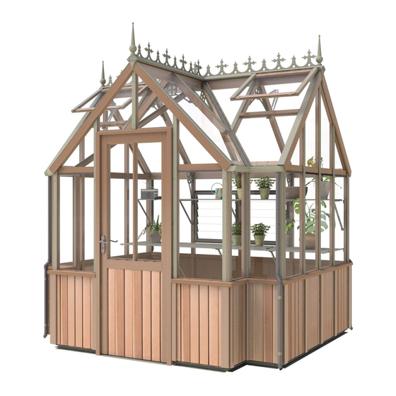
Summary of Contents for Alton VICTORIAN DURHAM
- Page 1 DURHAM PORCH HB 7 x 8 7 x 12...
-
Page 2: Table Of Contents
7’ Wide Victorian HB Cedar Greenhouse Assembly Instructions Contents: Section Page Introduction Base Preparation / Dimensions Overview Base Assembly 9-10 Rear Assembly 11-15 End Gable Assembly 16-21 Porch Assembly 22-25 Frame Assembly 26-28 Door Assembly 29-35 Roof Assembly 36-38 Mid Rail Assembly 39-40 Half Board Installation Louvre Installation... -
Page 3: Introduction
Introduction Thank you for purchasing your new Alton greenhouse. We recommend you familiarise yourself with the instructions and read all safety information before you commence assembly. HELPLINE: 0116 267 7091 Safety Warning Glass, aluminium and timber can potentially cause injury. Please ensure you wear protective goggles, gloves, headgear and suitable footwear when assembling and glazing the building. -
Page 4: Base Preparation / Dimensions
Finally, and most importantly, choose a site where your Alton Greenhouse will look right so that it will complement your garden. We cannot emphasis how important it is to have a proper base for your Alton Greenhouse to be erected upon. It is essential that the BASE IS FLAT, LEVEL AND SQUARE AS WELL AS BEING SUBSTANTIAL enough to take the weight of the greenhouse including its 3mm glass. - Page 5 Base Dimensions Recommended 3’ X 2’ Slab (2” thick) (910mm X 610mm) 2” thickness (50mm) Slab Base Size (Recommended) Note: The base should always be larger than 5 : 1 your building. Note: If a membrane is used this may hinder drainage.
-
Page 6: Overview
Overview To build your new greenhouse you will need the following tools: Spirit Level Pencil PZ2 Screwdriver Bit Cordless Screwdriver (2 would be ideal, 1 to drill and 1 to screw) 4mm Drill Bit 7mm Masonry Bit Hammer Drill Hammer Wooden/Rubber Mallet Tall step ladders x 2 Tape Measure... -
Page 7: Overview 2
Overview You can build the sides and gables flat on the ground and then with help or using a prop position the first one ready for installation. You then work your way around the greenhouse connecting each section. Once you have completed the gables and sides you can install the ridge and the roof. Glazing the structure is very simple but be very careful of the edges of the glass as the panes will break into tiny peaces if you catch an edge on a hard surface such as concrete. -
Page 8: Base Assembly
Base Assembly Diagram 1 Lay out your aluminium base sections as the diagram shows. Use the twist-in crop head bolts in the bolt channels for attaching the base brackets (D174M), EV0311M diagram 1. The base brackets should always be positioned either side of the door, in the corners, in the middle of the end gables and equally spaced down the side. -
Page 9: Rear Assembly
Rear Assembly To start building your greenhouse begin by laying out the components for your rear side flat on the ground like the diagram below. Use the tables below to identify your building length and the components with the part numbers and sizes. First of all drill pilot holes through the bottom of each mortise on the cill section (e.g.EV0018) (diagram 2, page 10). -
Page 10: Rear Assembly 4
Rear Assembly Internal Pilot hole, it is easiest to drill Diagram 2 down through the middle of the Make sure the side bars are pushed all the mortise to make way in, you may find they need a light tap sure you get the with a wooden mallet or something similar. -
Page 11: End Gable Assembly
End Gable Assembly (two required on this model) Internal Dia. 4 6ft End Gable x 1 EV0413 Part Name Part Size Number (mm) Rear Cill EV0404 1821 Roof Corner R EV0480 1324 Roof Corner L EV0481 1324 Side Corner R EV0502 1650 Side Corner L... - Page 12 End Gable Internal Now slot the 2 longer gable bars (EV0504 / EV0505) into the cill. These also need to locate with the Dia. 6 middle rear purling (diagram 6) . Diagram 6 Internal Next fit both left and right purlings (EV0408 / EV0414 to the standard glazing bars (EV0501).
-
Page 13: End Gable Assembly 5
End Gable Assembly You will need to drill a pilot hole in the bottom of each side corner bar as shown in diagram 7. This should Internal come through half way up the mortise slot. Now slot the side corner bar into place, fix the bottom Dia. - Page 14 Pilot hole End Gable Assembly here Dia. 9 Once the side corner bars are secure slot the above purling glazing bars into place. With all of the gable bars in place drill pilot holes through the lap joints at the end of each bar.
- Page 15 End Gable Assembly Diagram 11 External Dia. 12 Dia. 11 Diagram 12 With all the components now in place flip the gable end over so you now have the outside edge facing you. Be careful doing this as some of the parts are not completely supported, it is a good idea to have a helper at this point.
- Page 16 Porch Front Assembly Internal 6ft Porch Front Part Name Part Size Number (mm) Front Cill EV0005 Roof Corner R EV0480 1324 Roof Corner L EV0481 1324 Side Corner R EV0502 1650 Side Corner L EV0503 1650 Gable Purling R EV0408 Gable Purling L EV0414 Gable Bar R...
- Page 17 Porch Front Assembly Internal Dia. 14 EV0408 EV0414 Diagram 14 Now slot the purling bars into place, again as with the end assemblies these will be fixed later.
- Page 18 Porch Front Assembly Internal Drill the pilot holes again as diagram 15 shows. Fix the cill to the corner bar with an 80mm CSK screw. Dia. 16 Internal Dia. 15 Diagram 15 Diagram 16 Internal Internal As before (keeping the inside edges flush) drill a pilot hole close to the inside face of the purlings tenon (diagram 16), then fix with a 25mm countersunk screw.
- Page 19 Porch Front Assembly Slot the above purling glazing bars Internal into place ready to take the roof Dia. 17 corner bars. You should now drill the pilot holes shown in diagram 17. Pilot hole Diagram 17 here Slot the roof corner bars onto the gable Internal bars and fix with 40mm Pan Head screws (diagram 18).
- Page 20 Porch Front Assembly Flip each gable section over so you can fix the purling bars with 25mm countersunk screws (diagram 19). Diagram 19 Dia. 19 External External Porch Returns Assembly Your handed porch returns (diagrams 20 internal view, 23 Porch Returns external view) allow you to connect your end gable assemblies to the front porch assembly.
- Page 21 Diagram 21 80mm CSK Screws Porch Returns Assembly cont. Diagram 20 7 x 12 example Internal Dia. 21 50mm CSK Screws 80mm CSK Screws Dia. 22 Diagram 24 Diagram 22 Dia. 24 External 50mm CSK Screw central position on EV0791 10mm from top Dia.
-
Page 22: Frame Assembly
Frame Assembly Before you position your sections onto the aluminium base you should drill the pilot holes in the bottom of the end gable side corner bars (EV0502 / EV0503) shown in diagram 28. The position of these holes should be about 19mm from the side face and 30mm measured from the bottom end of the bar. -
Page 23: Frame Assembly 7
Frame Assembly External Diagram 27 Keep faces flush Diagram 28 Make sure the side corner bar is located correctly and the front face is flush with the end of the eaves bar, mark out the pilot hole positions shown in diagrams 29 and 30. Diagrams 31 and 32 on the next page show the direction the holes should be drilled in. - Page 24 Frame Assembly Before fixing this corner make sure the inside Diagram 31 faces are all flush (diagram 31). When you are happy that the purling is located correctly (it is normal that the purling is set back slightly from the glass rebate on the front of the building) start by inserting the 80mm screw through the side of the eaves bar into the tenon on the end of the purling.
- Page 25 Frame Assembly With help or using props for extra support, position the other end gable on to the base and repeat the steps from page 22 to 24. It is best NOT to fix this gable to the aluminium base at this point as you will want some adjustment when attaching the porch return side sections, but keep this supported at all times.
- Page 26 Door Installation Your door will arrive already installed in the frame with Diagram 34 the lock and lock plate attached. All you need to do is attach the door handle to install this to the building. Start by sliding the spindle through the top hole in the door (diagram 34), then locate one of the door handles on this and fix with the screws provided.
- Page 27 Door Installation Take the door to the greenhouse frame assembly Diagram 36 and slide it into place. Unlock and open the door so that it is 90 degrees to the frame as shown in the illustration on the next page. Fix through You will need to pack the outside edge of the open this face...
- Page 28 Door Installation Once the door frame is secure drill a pilot hole through the mortise slot in the door frame header (diagram 38). Dia. 37 50mm Screws Diagram 38 Slot the above door glazing bar (EV0471) into the mortise slot in the door frame header and secure it with a 50mm CSK screw (diagram 39).
-
Page 29: Roof Assembly
Roof Assembly Dia. 40 Diagram 40 You will need two sets of step ladders at this point and a helper. Slot the ridge bar (8’ - EV0445 / 12’- EV0447) onto the tenons of the roof corner bars at both gable ends of the building. -
Page 30: Roof Assembly 9
Roof Assembly Diagram 41 External Diagram 42 X-ray The central glazing bars should also have a pilot hole drilled and be fixed to the ridge bar with an 80mm CSK screw (diagrams 41-43). Diagram 43 X-ray... - Page 31 Roof Assembly Now the ridge is in place you can install the roof bars. Slot the bars into the ridge first, the tenon may be a little tight so this might require a tap with a wood or rubber mallet. Once this has located correctly locate the bottom of the bar with the trench in the eaves bar/s.
- Page 32 Roof Assembly With all the roof bars in place drill pilot holes vertically down through the roof bars, refer to diagram 30 (page 23) for the location of this hole. Make sure the roof bars are tight in to the eaves bar on the inside of the building and fix with 100mm screws (diagrams 45 and 46).
- Page 33 Before you begin construction of the porch roof you Roof Assembly firstly need to check that your building is square and level, are the internal diagonal measurements equal? With so many precision components meeting from different directions you need to take time now to aid construction throughout the rest of the build.
- Page 34 Your roof hip porch bars (EV0788) can now each be lowered Roof Assembly into place (pointed end towards the porch ridge) and secured with two 25mm csk screws at the top (diagram 49) and one at the bottom (diagram 50). Bottom view On each hip (EV0788) you will notice a notched out section on the underside face.
- Page 35 The handed roof jack glazing bars now need to be fitted, Roof Assembly see diagrams 55 and 56. They attach to the ridge and porch ridge as per previous roof bars using 80mm CSK screws. The bottom of each bar (EV0776, EV0777) rests onto the EV1159M brackets.
- Page 36 Once the greenhouse frame is up and secured to the Mid Rail Installation aluminium base using 25mm Pan Heads you can install the mid rails, starting with the rear side. 8ft long Part Name Part Size Number (mm) Front R EV0424 Front L EV0425...
- Page 37 Now Fit the mid rails to the end gables. Again slot Mid Rail Installation them into place, pilot drill internally and fix them with 50mm CSK screws through the gable bars and corner bar. Make sure the two mid rails are lined up well on the outside before fixing to the corner bar (diagram 60).
- Page 38 Continue fitting the mid rails working towards the Mid Rail Installation doorway using 50mm and 80mm CSK screws where appropriate. Remember to pilot drill the holes first and to keep all the joints nice and tight. 7 x 12 example EV0905 EV0903 EV0424...
-
Page 39: Half Board Installation
You can now insert the wooden half board panels Half Board Installation into the greenhouse frame. Start with the first panel on the rear side of the building and work your way round inserting all panels in their various sizes. The Half Board Panels cedar capping is fixed with 40mm or 50mm pan head screws (see next page), if it is not windy then... - Page 40 The capping comes in three styles see profiles Half Board Installation in the table. The corner capping is wider to cover the gap Half Board Capping created by the standard cap on the side of the building. It should be fitted up to this capping Part Name Part Profile...
- Page 41 Louvre x 1 Part Name Part Size Louvre Assembly Number (mm) Louvre Top/Bottom D165M To start building your louvre you first need to assemble the Louvre Side Insert D166M handed sides. Combine the two side sections with the two Louvre Side D168LM inserts, see diagram 62 to create the side assemblies.
- Page 42 Glass Size Code 78 712 EV457X496X39 (see diag.) Glazing EV405X920X515 (see diag.) Standard cedar capping or the upgrade aluminium capping? EV405X540X135 (see diag.) EV610X1345X838 (see diag.) If you have the Aluminium capping you EV556X810X23 (see diag.) need to slide the glazing rubber into EV610X725X218 (see diag.) channels on the back of the capping (see...
- Page 43 Glazing Note: All channels in the aluminium capping should have rubber inserted, even if it is going onto the timber. (x6) (x4) (x2) (x2) Keep the short flange pointing The louvre can replace any of the EV610 x 916 panes. upwards on the outside.
-
Page 44: Glazing (Part 1)
You need to decide where in the building you are having your Glazing (part 1) louvers. Below is an example of how it might be fitted. The louvre can replace any of the 610 x 916 panes, but make sure the handle operates and that there is no interference with the glass in the location that you choose. - Page 45 Glazing (part 1) Diagram 65 Glass retaining bead Dia. 65 External Diagram 66 External Silicone bead External Eaves Bar...
-
Page 46: Gutter And Downpipe Installation
Internal Louvre Glazing If you haven’t already done so you could now install the louvre glass (diagram 67). Make sure the tabs on the glass retainers are pinched slightly so they hold the glass tight. Standing on the inside of the building slot the first louvre slat in until it hits the bottom tab of the retainer. - Page 47 Gutter and Downpipe Installation Diagram 68 25mm Pan Screw Diagram 69 External Diagram 70 External The handed porch gutters are also secured with 25mm pane heads. They have a flexible black plastic insert (EV1168) in each re- turn corner which needs to be siliconed into place to stop the gutter joint...
- Page 48 Gutter and Downpipe Installation To install the downpipes straight to the floor cut the pipe as per the diagrams below. Use a small amount of silicone at each joint. The brackets can share the same hole as the capping for the panels.
- Page 49 Gutter and Downpipe Installation Diagram 73 If you want to connect the pipe to a waterbutt cut the pipe appropriately and simply use the D207 joints to divert the pipe. Its likely you will need to fix the downpipe brackets higher up, again try to use a standard capping screw location (diagram 73).
-
Page 50: Glazing (Part 2)
Glazing Next you need to decide on the location of your roof vents. These can NOT be fitted side by side. Once you have decided this start by installing the glass that goes underneath the vents. Use 2 of the glass stops (EV0313M) per pane (part 2) diagram 76. - Page 51 Glazing (part 2) External complete glazing by fitting the roof panes. Slide these all the way up the glazing bars, making sure they tuck into the groove in the ridge. Slot 2 of the glass stops (diagrams 78 and 79) on Diagram 78 and lower the pane down onto the eaves...
- Page 52 Glazing (part 2) Once all the glazing has been finished you can install the ridge cover caps. This is a universal part that can be used with either cedar or aluminium capping. Simply place this on top of the ridge bar and fix in place using 40mm Pan Head screws though the pre-drilled holes.
-
Page 53: Roof Vent Installation
Roof Vent Installation Dia. 81 Dia. 82 Take the vent frame that is ready assembled and fix the vent hinge to one Diagram 81 end through the 4 pre drilled holes using the 20mm screws, diagram 81. Once this is in place fix the plastic vent filler (EV0323) also with a 20mm screws, its is important to make a pilot hole before fixing the plastic filler to prevent... - Page 54 Roof Vent Installation Once you have assembled the roof vents you can now install them to your building. Prepare the ridge hinge (EV0314M) by running a bead of silicone along the back edge (diagrams 83 and 84). Diagram 83 External D220 EV0314M Diagram 84...
- Page 55 Roof Vent Installation Internal Dia. 87 Diagram 87 Now fit your autovents to the slam rail and to the bottom of the roof vents, diagram 87. Use 19mm screws to secure the top arm of the autovent to the roof vent, do this with the roof vent in the closed position so that you get the bracket in the correct...
-
Page 56: Optional Cresting
Optional Cresting Dia. 88 Diagram 88 From one end of the building and from the front of your porch slide your cresting pieces along channel in the ridge cover caps making sure they are in the correct orientation (diagram 88). -
Page 57: End Caps And Finials
End cap and Finial Diagram 89 X-ray Diagram 90 The end cap and finial bolt together with a 22mm M6 bolt. The easiest way to attach this is to slide the end cap onto the end of the ridge cover cap, then slide the bolt on the end cap (the head should locate in the lower recess of the end cap), with the bolt in... -
Page 58: Finish Installation
Diagram 91 Finish installation When you are happy with the final position of your greenhouse and all the sides are vertical and square greenhouse to the ground. Use brown rawl plugs, 50mm screws and a 7mm hammer drill to secure it through the base brackets previously attached... -
Page 59: Optional Auto Louvre Installation
Optional Auto Louvre Installation (part 1) Once the louvre is installed in the greenhouse you can replace the manual handle with the automatic unit. First of all remove the screw to release the arm (diagram 93). Next Remove the handle from the frame of the louvre (diagram 94). - Page 60 Optional Auto Louvre Installation (part 2) Offer the opener up to the Diagram 96 Diagram 99 frame with the plates and washers and slide the louvre arm into position. This now gives you the correct location for the opener (diagram 96). You now need to mark the frame and to drill two holes, use a 2.5mm drill bit...
-
Page 61: Parts Lists
Parts Lists EVPORCL8HB1 Evo Victorian with Porch Common Length 8ft Long **HB** ‐ 1 of 2 Quantity EV0016 Cill Side 8ft long EV0016 2476mm 1 EV0419 Eaves Bar 8ft long EV0419 2564mm 1 EV0438 Mid Rail Side 8ft EV0438 2564mm *HB* 1 EV0501 Glazing Bar Side EV0501 1588mm *HB* 3 EV0304M ALU Side Base 8ft long EV0304 2474mm **MOSS** 1 EV0622M ALU Vic Gutter 8ft long EV0622 2564mm **MOSS** 1 EVPORCL8HB2 Evo Victorian with Porch Common Length 8ft Long **HB** ‐ 2 of 2 EV0902 Porch Mid Rail 1ft Deep LH 1 EV0903 Porch Mid Rail 1ft Deep RH 1 EV0906 Porch Cill 1ft Deep 2 EV0908 Porch Eaves Rail 1ft Deep LH 1 EV0909 Porch Eaves Rail 1ft Deep RH 1 EV0325 ... - Page 62 EV0628M 1 ALU Vic Ridge Cap 8ft long EV0628 2602mm **MOSS** D211 Grey Downpipe Length 1625mm 2 EVPORHOU68P6B2 Evo Victorian with Porch 6x8 House Box ‐ 2 of 2 EV0313M Glass Stop EV0313 **MOSS** 12 EV0537M Alton Eaves Bracing EV0537 **MOSS** 4 EV0538M Alton Ridge Bracing EV0538 **MOSS** 2 EVPACVIC Victorian Component Pack 1 EVPACVENT Vent pack bundle for Evo 2 EVSMA01 Smalls Pack No 01 for Evolution 1 EVSMAVIC01 Smalls Pack No 01 for Victorian ...
- Page 63 1 EV0902 Porch Mid Rail 1ft Deep LH 329mm 1 EV0903 Porch Mid Rail 1ft Deep RH 329mm 1 EV0906 Porch Cill 1ft Deep 286mm 2 EV0908 Porch Eaves Rail 1ft Deep LH 373mm 1 EV0909 Porch Eaves Rail 1ft Deep RH 373mm 1 EV0293M ALU Front Base 5ft wide EV0293 500mm **MOSS** 2 EV0538M Alton Ridge Bracing EV0538 **MOSS** 1 EV1163M Porch Gutter 1ft deep LH 332mm **MOSS** 1 EV1164M Porch Gutter 1ft deep RH 332mm **MOSS** 1 EV1169M Porch Base 1ft deep LH 330mm **MOSS** 1 EV1170M Porch Base 1ft deep RH 330mm **MOSS** 1 D211 Grey Downpipe Length 1625mm 2 EVPACPOR Evo Victorian Porch Component Pack 1 ...
- Page 64 EV0251M ALU Roof Vent Capping EV0251 596mm **MOSS** 4 8 EV0688M ALU Vic Capping Roof 6ft wide EV0688 1328mm **MOSS** 3 7 EV0693M ALU Vic Capping Roof Corner 6ft wide EV0693 1328mm **MOSS** 4 EV1184M Porch Valley Jack Capping 6ft LH_Alu 849mm **MOSS** 1 Roof EV1185M Porch Valley Jack Capping 6ft RH_Alu 849mm **MOSS** 1 EV0598 Cedar Capping for HB Panel EV0598 668mm 13 17 Panels EV0599 Cedar Capping for HB Panel Corner EV0599 668mm 4 EV0227 Glazing PVC 10m (m700) 1729D10GP coil 7 ‐ Rubber EV0231 Glazing PVC 100m (m700) 1729D10GP coil ‐ Helpline 0116 267 7091 www.birstall.com alton@birstall.com...
Need help?
Do you have a question about the VICTORIAN DURHAM and is the answer not in the manual?
Questions and answers