Table of Contents
Advertisement
Advertisement
Table of Contents
Troubleshooting

Related Manuals for Human HumaStar 300


Summary of Contents for Human HumaStar 300
- Page 1 HumaStar 300 | Service Manual Cat No. 17901s/2...
- Page 3 No part of this documentation may be reproduced in any form, nor processed, copied or distributed by means of electronic systems, without prior permission of Human GmbH in writing. Since all precautionary measures were taken into account in producing these operating instructions, the manufacturer accepts no responsibility for any errors or omissions.
-
Page 5: Table Of Contents
1.2 uSeR WaRRanty 1.3 intended uSe of tHe inStRuMent 1.4 geneRal Safety WaRningS 1.5 diSpoSal ManageMent ConCept 1.6 inStRuMent diSinfeCtion 1.7 bioHazaRd WaRning 2 tHe analyzeR - HuMaStaR 300 2.1 geneRal deSCRiption 2.2 Main CHaRaCteRiStiCS 2.3 opeRation 2.4 uSeR WaRRanty 2.5 inStallation 2.5.1 Unpacking... - Page 6 2.8 SoftWaRe 3 oveRall bloCk diagRaMM (p/n: ei0110.01) 3.1 poWeR Supply ConneCtionS (p/n:ei0107.01) 3.2 Main poWeR Supply aSSeMbly (p/n: ay0097.04) 3.2.1 PCB Power Distribution (P/N: 17970/27) 3.2.2 Transformer (P/N: EM0050.01) 3.2.3 PC Power Supply (P/N: 17956/1) 3.2.4 Power Supply + 24V (P/N: 17956/2) 3.3 poWeR Supply boaRd (p/n: 17970/7) 3.4 poWeR Supply MaintenanCe 3.4.1 To remove the Power supply...
- Page 7 Contents 4.4.4 17970/24.A.PM (assembly drawing) 5 poWeR Supply pHotoMeteR laMp (p/n: 17970/10) 5.1 tRouble SHooting guide 5.2 SpaRe paRt liSt 5.3 enCloSed doCuMentation 5.3.1 17970/10.A.SC (electrical diagram) 5.3.2 17970/10.A.PM (assembly drawing) 6 MiCRopRoCeSSoR aSSeMbly (p/n: ea0073.02) 6.1 Cpu Slave (p/n:17970/8) 6.2 MotHeR boaRd (p/n: 17970/9) 6.3 MaintenanCe 6.3.1 CPU slave board replacement...
- Page 8 8.5 tRouble SHooting guide 8.6 SpaRe paRt liSt 8.7 enCloSed doCuMentation 8.7.1 17970/26.A.SC (electrical diagram) 8.7.2 17970/26.A.PM (assembly drawing) 8.7.3 17970/26.A.SC (electical diagram) 8.7.4 17970/26.A.PM (assembly drawing ) 8.7.5 EB0092.01.A.SC (electrical diagram) 8.7.6 EB0092.02.A.PM (assembly drawing) 8.7.7 EB0092.03.A.PM (assembly drawing) 8.7.8 EB0092.04.A.PM (assembly drawing) 8.7.9 EB0092.05.A.PM (assembly drawing) 8.7.10...
- Page 9 Contents 10.5.3 EB0033.02.A.SC (electrical diagram) 10.5.4 EB0033.03.A.SC (electrical diagram) 10.5.5 EB0033.03.0.PM (assembly drawing) 10.5.6 EB0122.01.0.SC (electrical diagram) 10.5.7 8EB0122.01.0.PM (electrical drawing) 11 enCodeR MotoRe 11.1 enCodeR MotoR + HoMe (p/n eb0120.01) 11.2 MaintenanCe 11.2.1 Replacement of the Encoder board 11.3 tRouble SHooting guide 11.4 SpaRe paRt liSt 11.5 enCloSed doCuMentation 11.5.1 EB0072.01.A.SC (electrical diagram)
- Page 10 14 CoMputeR Module (p/n: ay0096.01, p/n: ay0199.01) 14.1 CoMputeR pC MaSteR (p/n: 17889) 14.2 paSSive boaRd 6 Slot iSa buS (p/n: 17810/7) 14.3 Multi - SeRial poRt (p/n: 910.002.031) 14.3.1 Check and the configuration multi-serial board parameters 14.4 ConfiguRation of bioS 14.5 to inStall SoftWaRe fRoM Cd-RoM to HaRd deSk 14.5.1 To Save the SW Archives 14.5.2 Preparation HW...
- Page 11 Contents 16 HydRauliC SySteM (p/n: Hy0012.01) 16.1 HydRauliCS of tHe SaMpling SySteM 16.2 HydRauliCS of tHe inCubation batH 16.3 HydRauliCS of WaSHing and dRying tHe CuvetteS 16.4 WaSte HydRauliCS 16.5 MaintenanCe 16.5.1 General RuLes 16.5.2 Peristaltic Pumps 16.6 tRouble SHooting guide 16.7 SpaRe paRt liSt 16.8 enCloSed doCuMentation 16.8.1 HY0012.01.F.CM (Hydraulic diagram page 1 out of 4)
- Page 12 18.2.3 Reaction and Measurement System Checks 18.3 deviCed foR MaintenanCe 18.3.1 To remove casing 18.4 pHotoMeteR Module 18.4.1 Photometer 18.4.2 To Equalize and Replace Filters 18.4.3 Replace Motor and Belt. 18.4.4 Replace and clean lenses 18.5 teMpeRatuRe adjuStMent and ContRol 18.5.1 Check Temperature in Incubation Bath 18.5.2 Check Temperature in the Reagent Chamber 18.6 pRepaRation SySteM...
- Page 13 Contents 19 geneRal tRouble SHooting guide 19.1 pRobleMS WitH poWeR Supply 19.2 pRobleMS WitH MaSteR CoMputeR and itS Cpu SlaveS 19.3 pRobleMS WitH diluteR 19.4 MeCHaniCal MoveMent pRobleMS 19.5 teMpeRatuRe pRobleMS 19.6 pRobleMS WitH pHotoMeteR, pRe-aMplifieR and laMp 19.7 pRobleMS WitH unReliable ReSultS 19.8 pRepaRation pRobleMS 19.9 pRobleMS WitH level SenSoRS and MiXeR 19.10 pRobleMS Cooling SySteM...
- Page 14 21 optional ModuleS 21.1 baR Code ReadeR 21.1.1 Bar Code Reader Interface (P/N: EB0111.01) 21.1.2 Assembly Procedure and Maintenance 21.1.3 Bar Code Reader Optical Alignment 21.1.4 Trouble Shooting Guide 21.1.5 Spare Part List 21.2 doCuMentation 21.3 iSe Module (p/n: kg0019.04) 21.3.1 Introduction 21.3.2 Some Highlights and Specifications 21.3.3 ISE Control Board (P/N: EB0181.02)
- Page 15 Contents...
- Page 17 Contents...
-
Page 19: Safety Instructions
HUMAN, not regularly maintained, used with equipment not approved by HUMAN or used for purposes for which it was not designed. -
Page 20: Intended Use Of The Instrument
1.4 general Safety Warnings Use only chemical reagents and accessories specified and supplied by HUMAN and/or mentioned in this manual. Place the product so that it has proper ventilation. The instrument should be installed on a stationary flat working surface, free from vibrations. -
Page 21: Disposal Management Concept
1.6 instrument disinfection Analytical instruments for in vitro diagnostic involve the handling of human samples and controls which should be considered at least potentially infec- tious. Therefore every part and accessory of the respective instrument which may have come into contact with such samples must equally be considered as potentially infectious. -
Page 22: Biohazard Warning
1.7 biohazard warning Analytical instruments for in vitro diagnostic application involve the handling of human samples and controls which should be considered at least potentially infectious. Therefore every part accessory respective instrument which may have come into contact with such samples must equally be considered as potentially infectious. - Page 23 safety InstruCtIons notes:...
- Page 24 gerätename | User manual...
-
Page 25: The Analyzer - Humastar 300
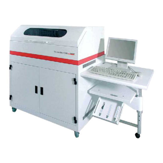
2 tHe analyzeR - HuMaStaR 300 2.1 general description HUMASTAR 300 – is an automatic Random Access Clinical Chemistry Analyzer. HUMASTAR 300 – with its sophisticated updated software offers great versatili- ty and speed of operation. Its unique characteristics and user friendliness make this analyzer the top in its class with its productivity and throughput of 300 Clinical Chemistry tests plus 180 ISE tests per hour. - Page 26 SaMple CapaCity: 40 PRIMARY TUBES or small plastic sample cups; including 16 places reserved for Standards and Controls, plus 4 places for STATS. Possibi- lity to add samples continuously during operation, up to 240 Patients with up to 30 different chemistries can be processed at a time. Reagent CapaCity: 30 On-line reagents.
- Page 27 - humastar 300 liquid level SenSoR: both the reagent and Sampling Probes have built-in liquid sensors and mixer to assure a correct sample preparation. keyboaRd: a full keyboard for easy programming of patients with demogra- phics, including a mouse for easy operation and navigation inside the software.
-
Page 28: Operation
bi-diReCtional inteRfaCe: via a built-in serial port RS 232/C connection to EDP systems. 2.3 operation The analyzer is a self sufficient system that uses some peripherals, such as Mo- nitor, Mouse, keyboard and printer. The analyzer consists in three parts: - Reagent plate Chamber: plate containing 30 On-line reagents with a choice to cool or leave the reagents at room temperature. -
Page 29: User Warranty
HUMAN shall replace or repair any defective item in its factory in Rome at no charge, except transportation changes. Instruments for repair have to be sent to HUMAN with all transportation charges prepaid. -
Page 30: Installation
2.5 installation 2.5.1 unpaCking Shipping and packing materials have been selected to provide maximum pro- tection during transportation under normal handling conditions. notice: once the carrier has taken possession of the system for transportati- on from the factory, carrier assumes all liability until delivery. -
Page 31: Installation
At the time of installation the system will be checked to ensure proper ope- rations. During installation, at least one person in the laboratory will be trained in operation and maintenance of the ANALYZER. The HUMASTAR 300 a highly sophisticated, high precision, sensitive instrument. Proper installation will ensure optimum performance. 2.5.3 enviRonMental RequiReMentS The system should be mounted on a table or workbench in an area free from vibration, draughts, dust, strong magnetic fields or direct sunlight.1.4.4. -
Page 32: Power Requirements
2.5.6 poWeR RequiReMentS A standard 230 Volt/50 Hertz or 115 Volt/60 Hertz - 400 Watts power is re- quired, as indicated on the back of the instrument. A 3-wire outlet is used to assure proper electrical grounding. If the laboratory power supply varies by more than 10%. It is recommended to install an external stabilizer an UPS no break with a minimum rating is 500 VA. -
Page 33: Connections In The Back Of The Analyzer
- humastar 300 2.6.2 ConneCtionS in tHe baCk of tHe analyzeR figuRe 6 Connections in the back of Analyzer 1. Power supply input socket (10). Make sure there is a proper GND. 2. Power Switch ON/OFF (11). 3. Power input socket for AIR PUMP (12). -
Page 34: Hydraulic Connections
2.6.3 HydRauliC ConneCtionS figuRe 7 Hydraulic Connections note: use only bi-di- stilled water for the in- cubation bath. Connect as „Figure 7“, Waste container, Wash Solution, Liquid for incubation bath. WaSH Solution: Fill container with 5 liters of dist. water and add 3 drops of tween 20. -
Page 35: Analyzer Components
2.7 analyzer Components 2.7.1 MonitoR HUMASTAR 300 can operate with every type of monitor (CRT or LCD) as long as it has a 15 pin VGA connector. The monitor with the help of the graphic software will guide the operator step by step through all operations. When needed click on (?) HELP a detailed help page will be displayed. -
Page 36: Reagent Chamber
figuRe 9 Analytical System analytical plate 2.7.4 Reagent CHaMbeR The reagent plate is devided into 30 compartments to contain 50 ml reagent bottles. l (cod. 17950/S) or 5 ml (cod. 17905/S) by means of an adaptor (cod. 17906/S). Cooling can be selected individually for each reagent, by opening a window to let forced cool air to penetrate. -
Page 37: Reagent Arm
- humastar 300 2.7.5 Reagent aRM The Reagent Arm holds the Probe which is connected to the diluter. The Pro- be aspirates the reagent and deposits it into the reaction cuvette. The Arm has three positions: Reagent bottle – reaction cuvette – washing well. The Reagent... - Page 38 17961/1 tube - 5ml The segments are available for primary tubes of 16x100 and 12.5x75 mm. The pre-dilution cups are available from HUMAN. Code 18720/31. Sample ID can be programmed manually using a Bar Code Reader, or an optical pen.
-
Page 39: Sampling Arm
- humastar 300 2.7.7 SaMpling aRM The sampling Probe is connected to the Diluter to aspirate the sample to be ana- lyzer from the Sample Plate and transferred into the reaction-cuvette and mix it with the warm reagent. The sampling Arm moves to several positions:... -
Page 40: Probe Washing Well
2.7.8 pRobe WaSHing Well The washing and cleaning of the Probe is impor- figuRe 14 tant to avoid carryover or contamination. After Washing Station each operation the Probe enters the Washing well, where it is washed internally by Pump P1 and externally by Pump P P5 with wash solution and finally it is dried externally by an air jet to eliminate any wash residue or drops. - Page 41 - humastar 300 figuRe 15 (17915 sample dilutor w syringe 17916 reagent dilutor w syringe Reagent Syringe = 1000 µl max. (cod. 17916/1 – syringe with piston) Sample Syringe = 600 µl max. (cod. 17915/1 – syringe with piston) Syringe holder valve (cod.
-
Page 42: Peristaltic Washing Pumps
700 nm. 2.8 Software The HUMASTAR 300 software has been divided into 8 parts in order you make it easy and user friendly for the operator, all smartly enclosed in a book form. Detailed information and procedures are described in the “Operator’s Manual”. - Page 43 - humastar 300...
- Page 44 gerätename | User manual...
- Page 45 overall BloCk DIagramm (P/n: eI0110.01) 3 oveRall bloCk diagRaMM (p/n: ei0110.01) teCHniCal deSCRiption This Block Diagram is the basic guide to find all the necessary information about the Analyzer. It shows graphically all the connections between the modules and the PCB’s. doCuMentation EI0110.01.0.DW (block diagram) 3.1 power Supply Connections (p/n:ei0107.01)
- Page 46 Power supply voltages SPS.PC FUSE F1 2,5A + 5 VDC FOR DIGITAL CIRCUIT EA0067.02 EB0046.01 PC COMPUTER ADC CONVERTER INTERNAL CIRCUIT EB0089.01 EB0089.01 PCB DC-DC CONVERTER FUSE F1 1,6A +11 VDC PHOTOMETER LAMP EB0054.01 EB0054.01 SPS.PC -12 VDC MULTISERIAL PORT EA0067.02 SPS.PC + 12 VDC...
-
Page 47: Pcb Power Distribution (P/N: 17970/27)
overall BloCk DIagramm (P/n: eI0110.01) 3.2 Main power Supply assembly (p/n: ay0097.04) teCHniCal deSCRiption This section describes all the Power Supply parts. The module generates the following voltages: + 5.0 V - 5.0 V + 12 V - 12 V + 24 V 18 Vac 48 Vac... -
Page 48: Pc Power Supply (P/N: 17956/1)
3.2.2 tRanSfoRMeR (p/n: eM0050.01) teCHniCal deSCRiption The transformer T1 becomes a gal- vanic separator and has two prima- ries both at 230 and 115 Vac. Primary (PH1 - PH2) 230/115 Vac Secondary (S1+S2) 18-0-18 Vac Secondary (S3) 48 Vac Secondary (S4) 230 Vac doCuMentation EM0050.01.B.SC (electrical diagram) 3.2.3 pC poWeR Supply (p/n: 17956/1) -
Page 49: Power Supply + 24V (P/N: 17956/2)
overall BloCk DIagramm (P/n: eI0110.01) 3.2.4 poWeR Supply + 24v (p/n: 17956/2) teCHniCal deSCRiption This module is supplied from the se- condary 230V transformer EM0050.01 and supplies the stabilized + 24V for the motors and to the power supply of the photometer lamp. - Page 50 Block diagram EB0043.01 Power supply +23 / -23 V Power supply 48 VAC 48VAC Input AC voltage +23 / -23 V Output Power supply analogic +15V voltage +15 V Incubation incubation bath bath control +15 V +12 V Refrigerator Input +12 V refrigerator control +24 V...
-
Page 51: Power Supply Maintenance
overall BloCk DIagramm (P/n: eI0110.01) Closed figuRe 18 Closed Setting Jumpers Closed Ref. test point Range note figuRe 19 < 2,75 V ± 0,05 Adj. R48 Nominal voltages +5 V ± 0,1 Adj. R47 +3,075 V ± 0,05 Adj. R26 R38 side VR2 +5 V ±... - Page 52 5. To access inside the power supply, remove screws (3) and its back panel (1). figuRe 20 gerätename | User manual...
-
Page 53: Replacement Of The Pc Power Supply
overall BloCk DIagramm (P/n: eI0110.01) 3.4.2 ReplaCeMent of tHe pC poWeR Supply 1. Disconnect connectors J2, J3, J4 from board (5) see „Figure 20“, remove screws (3) from the top panel and remove the panel (4). 2. Remove the input connector of 220Vac (black cable) from J4 the distribution board (8), see „Figure 21“. -
Page 54: Fuse Replacement
3.4.4 fuSe ReplaCeMent use fuses as indicated on the name plate. Make sure to reinert the fuse contai- ner selecting the right voltage. indicated by the symbol . Remove the power cord and extract the fuse container (17). 3.4.5 to ReplaCe tRanSfoRMeR 1. -
Page 55: Replace Power Supply + 24V
3.5 trouble Shooting guide This section lists a series of possible problems and how to solve them. In order to identify some of these problems, it is necessary to use the Diagnostic Program “HUMASTAR 300 TOOLS“. defect Causes and Remedies Make sure that the power cord is well inserted. - Page 56 Replace the fuses as described above. Disconnect the cord that is connected to the AUX plug. Turn ON the analyzer. if the problem persists: the fuses are fre- Disconnect all connectors J1, J2, J3, J4 from the power quently burnt supply board 17970/7.
- Page 57 overall BloCk DIagramm (P/n: eI0110.01) Check the PWR ON voltage of the Sampling System. Replace F4 Missing the + 24v in If fuse burns – disconnect J8 Sampling System Check voltage VDC on J2, board 17970/7, if necessary replace the power supply +24V - 17956/2 Replace board 17970/7 Check the PWR ON voltage of the Cuvette System Replace F3...
- Page 58 Check fuse F5 – F8 Check voltage +12V between terminals 7-8 J10, board 17970/7 Check +15V on terminal 8 of U3, on board 17970/7 Check voltage on TP3 < +2,75V board 17970/7, if neces- Refrigeration in Re- sary adjust with R48 agent Chamber does not cool.
-
Page 59: Spare Parts
BloCk DIagramm (P/n: eI0110.01) 3.6 Spare parts to assure a rapid and effici- ent technical service to its clients HuMan suggests to keep in stock all the parts mar- ked with the symbol (•). Order requests have to have the fol-... - Page 60 Fuse (int.) f5H250v (Φ 5x20 mm) per 680.010.250 230 Vac Fuse (int.) f8H250v (Φ 5x20 mm) per 680.010.280 115 Vac Power cord with AUX socket – for AIR EA0066.01 PUMP WC0066.01 Power cord +24 V WC0067.01 Power cord 230 Vac WC0068.01 Power cord AIR PUMP signal WC0105.01...
-
Page 61: Enclosed Documentation
overall BloCk DIagramm (P/n: eI0110.01) 3.7 enclosed documentation 3.7.1 ei0110.01.0.dW (bloCk diagRaM) 3.7.2 ei0107.01.0.dW (bloCk diagRaM) 3.7.3 ei0107.01.0.SC (eleCtRiCal diagRaM) 3.7.4 17970/27.b.SC (eleCtRiCal diagRaM) 3.7.5 17970/27.a.pM (aSSeMbly dRaWing) 3.7.6 eM0050.01.b.SC (eleCtRiCal diagRaM) 3.7.7 ea0067.02.0.SC (eleCtRiCal diagRaM) 3.7.8 17970/7.a.SC (eleCtRiCal diagRaM) 3.7.9 17970/7.b.pM (aSSeMbly dRaWing) - Page 62 gerätename | User manual...
- Page 63 overall BloCk DIagramm (P/n: eI0110.01)
- Page 64 gerätename | User manual...
- Page 65 overall BloCk DIagramm (P/n: eI0110.01)
- Page 66 gerätename | User manual...
- Page 67 overall BloCk DIagramm (P/n: eI0110.01)
- Page 68 gerätename | User manual...
- Page 69 overall BloCk DIagramm (P/n: eI0110.01)
- Page 70 gerätename | User manual...
- Page 71 overall BloCk DIagramm (P/n: eI0110.01)
- Page 72 gerätename | User manual...
-
Page 73: Interface Pump - Valves (P/N: 17970/24)
InterfaCe PumP - valves (P/n: 17970/24) 4 inteRfaCe puMp - valveS (p/n: 17970/24) teCHniCal deSCRiption The present functions are devided into three sections. diagram 17970/24.SC page 1 of 3 include: Control Valve V4 via U1, OC2 and Control valve V5 via U1, OC1 and Control pump P6 by means of si- gnal E_P6C that enables the inte- grated circuit U2. - Page 74 diagram 17970/24.SC page 2 of 3 include: Distribution of signals (CK, LP, EN, CW-CCW, SYNC) to control diluter D1 via board 17970/11. Distribution of signals (E_P1CA, LP, CK) to control pump P1 via board EB0033.03. Distribution of signal E_P4CA to control pump P4 via board EB0033.02. Control pump P8 via U1, OC6 and Q6.
-
Page 75: Maintenance
InterfaCe PumP - valves (P/n: 17970/24) Closed table 2 Setting jumpers documentation 17970/24.a.SC (electric diagram pag. 1/3) 17970/24.a.SC (electric diagram pag. 2/3) 17970/24.a.SC (electric diagram pag. 3/3) 17970/24.a.pM (assembly drawing) 4.1 Maintenance Remove the outside panels: (see “General Maintenance“ section “To remove operations to be done outside panels”). -
Page 76: Trouble Shooting Guide
4.2 trouble Shooting guide This section its a series of symptoms or problems and how to solve them. To solve some of the problems use the Diagnostic Program “HUMASTAR 300 TOOLS“. defect Causes and Remedies Check the voltage PWR ON of the Reagent System (See also „3.5 Trouble Shooting Guide“.) - Page 77 InterfaCe PumP - valves (P/n: 17970/24) Check the start voltage PWR ON of the measuring cuvette system. (See also „3.5 Trouble Shooting Guide“.) Check voltage +24V on J6 (DL2 ON) Check fuse F1 pump p7 does Check the resistance of the motor, should be about 25 ohm, not start if necessary replace.
-
Page 78: Spare Part List
Code Sub_Code description and fast technical ser- 17970/24 Pump and valve driver interface vice, HuMan suggests to 680.010.225 Fuse 2,5A keep in stock the parts in- dicated with (•). When or- dering make sure to give 4.4 enclosed documentation... - Page 79 InterfaCe PumP - valves (P/n: 17970/24)
- Page 80 gerätename | User manual...
- Page 81 InterfaCe PumP - valves (P/n: 17970/24)
- Page 82 gerätename | User manual...
- Page 83 InterfaCe PumP - valves (P/n: 17970/24)
- Page 84 gerätename | User manual...
-
Page 85: Power Supply Photometer Lamp (P/N: 17970/10)
Power suPPly Photometer lamP (P/n: 17970/10) 5 poWeR Supply pHotoMeteR laMp (p/n: 17970/10) technical description The function of this board is to generate a stabilized voltage of +11V for the Photometer lamp. The output voltage can be adjusted with PR1. item test point Range... -
Page 86: Trouble Shooting Guide
5.1 trouble Shooting guide This section lists a series of Symptoms or Problems and how to solve them. To solve some of the problems use the Diagnostic Program “HumaStar 300 TOOLS “. defects Causes and Remedies Check if the lamp is interrupted... -
Page 87: Enclosed Documentation
Power suPPly Photometer lamP (P/n: 17970/10) 5.3 enclosed documentation 5.3.1 17970/10.a.SC (eleCtRiCal diagRaM) 5.3.2 17970/10.a.pM (aSSeMbly dRaWing) - Page 88 gerätename | User manual...
- Page 89 Power suPPly Photometer lamP (P/n: 17970/10)
- Page 90 gerätename | User manual...
- Page 91 mICroProCessor assemBly (P/n: ea0073.02) 6 MiCRopRoCeSSoR aSSeMbly (p/n: ea0073.02) teCHniCal deSCRiption The system consists of a PC (MASTER) and three µprocessors (SLAVES). SLAVE (1) controls the complete robotics of the Reagent System such as: Rotation of the Reagent plate Movement of the Arm with its Reagent Probe. Reagent Diluter and its pump SLAVE (2) controls the whole Analytical System (cuvette system), such as: Rotation of the measuring cuvette plate...
-
Page 92: Cpu Slave (P/N:17970/8)
6.1 Cpu Slave (p/n:17970/8) teCHniCal deSCRiption The structure of this board is shown in block diagram EB0045.XX and its electri- cal diagram EB0045.00.B.SC. The processor unit (U1) consists of a microcontroller U1, a memory RAM (U3) and a programmed memory (U2) including a bidirectional I/O port. The serial transmission unit RS-232 (U10) is used to Transmit/Receive data bi-directionally to the PC master. - Page 93 mICroProCessor assemBly (P/n: ea0073.02) all voltages are referred to gnd-a = gnd-d = tp2 = tp3 (with jp1 closed) closed table 5 open Settings jumpers board description device layout Ref. Software p/n table 6 EPROM 27C2001 17970/8 PD0052.01 List of programmable devices EEPROM 256 K 17970/8 GAL16V8...
- Page 94 Signal Sensor Reagent SENSOR_LR Level Flag Home Reagent HOME_PRR Probe Flag Home Reagent HOME_PIR Plate Flag Home Reagent HOME_BRR Flag Sync Diluter D2 SYNC_DR Reagents SYNC_0 SYNC_1 SYNC_2 A_CLKR Signal Clock B_CLKR Signal Clock E_P4R Enable Start Pump P4 ONC_R Start Air Pump Direction Reagent PR_CWR...
- Page 95 mICroProCessor assemBly (P/n: ea0073.02) E_BRR Start Reagent Arm E_PIR Start Reagent Plate Low power Motor D_LOWR Diluter D2 Low power Motor P2_LOWR Pump P2 Low power Motor BR_LOWR Reagent Arm Low power Motor PI_LOWR Reagent Plate Low power motor PR_LOWR Reagent Probe E_MIXERR Start Mixer...
- Page 96 Flag [Wash] Minimum SENSOR_S3C Liquid Level inside Wash So-lution Container Flag [tb High] Maxi- SENSOR_S4C mum Liquid Level inside Incu-bation chamber Flag [tb low] Minimum SENSOR_S5C Liquid Level inside Incu- bation chamber TEMP_BTC Temperature Incubation chamber C_BUSY Busy line A/D converter HOME_PRHIC Flag Position High Cu- vette Washing Arm START...
- Page 97 mICroProCessor assemBly (P/n: ea0073.02) I2CSCLC Serial Clock Line E_P7C Enable Start Pump P7 D0_C Bit D0 A/D D1_C Bit D1 A/D D2_C Bit D2 A/D D3_C Bit D3 A/D D4_C Bit D4 A/D D5_C Bit D5 A/D D6_C Bit D6 A/D D7_C Bit D7 A/D Reset Micro-controller...
- Page 98 +12V Power supply 12v AGND Ana logic GND TX232CA Transmission Data Line RX232CA Receiving Data Line HOME_DCA Flag Home Diluter D1 Samples SENSOR_LCA Signal Sensor Sample Li- quid Level HOME_PRCA Flag Home Sample Probe HOME_PICA Flag Home Sample Plate HOME_BRCA Flag Home Sampling Arm SYNC_DCA Flag Sync Diluter D1 Sample...
- Page 99 mICroProCessor assemBly (P/n: ea0073.02) PWR_ONCA +24/Vcc On/Off Sam- pling System I2CSDACA Serial Data Line I2CSCLCA Serial Clock Line E_DCA Enable Diluter D1 Sam- E_P1CA Enable Pump P1 E_BRCA Enable Sampling Arm E_PICA Enable Sample Plate D_LOWCA Low power motor Diluter Low power motor Pump P1_LOWCA Low power motor Sam-...
-
Page 100: Mother Board (P/N: 17970/9)
6.2 Mother board (p/n: 17970/9) teCHniCal deSCRiption The Mother Board receives all the signals from the three CPU slaves, A/D Conver- ter as well as from all the other modules present in the analyzer. The functions of the board 17970/9 are: To Interface the CPU, Reagents, Measurement and Sampling Systems, in connectors J14, J17 e J15 To Interface the A/D converter board, in connector J23. - Page 101 mICroProCessor assemBly (P/n: ea0073.02)
- Page 102 figuRe 24 0,25 µ s ± 0,005 = 4MHz 7 ms ± 0,5 Clock Signal U9, terminal TP6 ≥ + 2 Vpp figuRe 25 Clock Signal U3, terminal TP5 item test point Range table 7 From + 11,0V to + 12,5V Nominal Voltages From + 4,75V to + 5,25V Pin 1 J24...
-
Page 103: Maintenance
mICroProCessor assemBly (P/n: ea0073.02) board description device layout Ref. Software p/n 17970/9 Mother Board GAL16V8 PD0040.01 figuRe 28 17970/9 Mother Board PIC16F84A PD0042.01 List of Pragrammable 17970/9 Mother Board GAL16V8 PD0041.01 Devices 17970/9 Mother Board GAL16V8 PD0040.01 doCuMentation 17970/9.A.SC (electrical diagram) 17970/9.B.PM (assembly drawing) 6.3 Maintenance... -
Page 104: Trouble Shooting Guide
6.4 trouble Shooting guide This section lists a series of symptoms and problems and how to solve them. To solve some of the problems use the Diagnostic Program “HUMASTAR 300 TOOLS“. defect Causes and Remedies there are no flag WaRningS on... - Page 105 mICroProCessor assemBly (P/n: ea0073.02) Possibly the sensor inside the incubation bath is damaged. Remove connector from cable WC0099.01 and check that the green DL4 no flag WaRning is given when is ON, otherwise: liquid level inside incubation Check the continuity of connection Sen- bath is low (tb loW) sor-Cable-Connector.
- Page 106 Missing the +5V power supply, Check fuse When turning on the analyzer, Check on J1 +5V (pin 1-2/3-4) no acoustic (beep) is heard from If fuse is burned, remove all the flat cables, the Cpu slave board. then insert one at a time to identify the one that cause the fuse to blow.
-
Page 107: Spare Part List
CPU slave 17970/8 technical service to its clients, PD0052.01 EEPROM U2 HuMan suggests to keep in stock PD0011.01 Programmable Device U5 all the parts that are marked with PD0012.02 Programmable Device U7 (•). When Ordering parts, make... -
Page 108: Enclosed Documentation
6.6 enclosed documentation 6.6.1 eb0045.00.b.SC (eleCtRiCal diagRaM) 6.6.2 17970/8.a.pM (aSSeMbly dRaWing) 6.6.3 17970/9.a.SC (eleCtRiCal diagRaM) 6.6.4 17970/9.b.pM (aSSeMbly dRaWing) gerätename | User manual... - Page 109 mICroProCessor assemBly (P/n: ea0073.02)
- Page 110 gerätename | User manual...
- Page 111 mICroProCessor assemBly (P/n: ea0073.02)
- Page 112 gerätename | User manual...
- Page 113 mICroProCessor assemBly (P/n: ea0073.02)
- Page 114 gerätename | User manual...
-
Page 115: Diluter Driver (P/N: 17970/11)
DIluter DrIver (P/n: 17970/11) 7 diluteR dRiveR (p/n: 17970/11) teCHniCal deSCRiption This PCB commands the stepper motor of the Diluter, which transforms the screw rotation into a linear movement of the syringe. Led (D1) is on, indicating the presence of the + 24v power supply. The mechanical zeRo position of the screw is obtained when both signals HoMe e and SynC are aligned. - Page 116 item test point Range figuRe 29 Pin 1 J2 From +23,5V to +24,5V Nominal Voltages Pin 20 U1 From +4,75V to +5,25V From +690 to +710mV Reg. PR1 (with Pin 15 U2 piston moving) Da +90 a +120mV (with piston in stand Pin 15 U2 still) all voltages are referred to gnd-d = gnd-a = tp3...
-
Page 117: Maintenance
DIluter DrIver (P/n: 17970/11) 7.1 Maintenance Remove the outside panels. (see “General Maintenance” – removal of outside panels) 7.1.1 ReplaCeMent of dRiveR boaRd (See Figure 29) operation to be done with the analyzer turned off. for diluter mainte- nance see Section 13 figuRe 31 1. -
Page 118: Trouble Shooting Guide
7.2 trouble Shooting guide This section lists a number of symptoms and problems and how to solve them. To solve some of the problems use the Diagnostic Program “HumaStar 300 toolS“. defect Causes and Renedies Check the start up voltage of PWR ON of the Reagent and Sampling Systems. -
Page 119: Spare Part List
DIluter DrIver (P/n: 17970/11) 7.3 Spare part list to assure a rapid and ef- Code Sub_Code description ficient technical assi- 17915 Complete Sample Diluter Module stance to its clients, Hu- 17916 Complete Reagent Diluter Module Man suggests to keep in ... - Page 120 gerätename | User manual...
- Page 121 DIluter DrIver (P/n: 17970/11)
- Page 122 gerätename | User manual...
-
Page 123: B Motor Control Motor (P/N: 17970/26)
motor Control assemBly (P/n:ay0113.01, ay0114.01) 8 MotoR ContRol aSSeMbly (p/n:ay0113.01, ay0114.01) teCHniCal deSCRiption Containers AY0113.01 AY0114.01 hold the modules that control the stepper motors. On the side of AY0114.01 is inserted the power supply board for the photometer lamp. 8.1 M/b Motor Control Motor (p/n: 17970/26) teCHniCal deSCRiption The function of this module is to interface the drivers that control the stepper motors of the Sampling System and that of the Cuvette Measuring System. - Page 124 In fig. 30 are indicated the modules in container AY0113.01 17970/22 17970/23 17970/20 17970/21 17970/20 figuRe 32 We highly suggest not to modify the positions of the modules. When re- placing - use modules with the same codes indicated in front of each module.
-
Page 125: B Motor Control (P/N: 17970/26)
motor Control assemBly (P/n:ay0113.01, ay0114.01) Closed figuRe 33 Settings jumpers doCuMentation 17970/26.A.SC (electrical diagram) 17970/26.A.PM (assembly drawing) 8.2 M/b Motor Control (p/n: 17970/26) teCHniCal deSCRiption The function of this module is to interface the drivers that control the stepper motors in the Sampling and the Cuvette measuring Systems. The Interface has the following characteristics: J1 and J2: input +24V for driver modules J3: input signals from cuvette plate activated via transition into driver mo-... - Page 126 In „Figure 34“ are shown the modules in container AY0114.01 17970/25 17970/21 17970/20 17970/20 figuRe 34 We highly suggest not to modify the positions of the mo- dules. When replac-ing - use modules with the same codes indicated in front of each module. REAGENT ARM REAGENT PLATE REAGENT PROBE...
- Page 127 motor Control assemBly (P/n:ay0113.01, ay0114.01) Closed table 8 Setting jumpers doCuMentation 17970/26.A.SC (electrical diagram) 17970/26.A.PM (assembly drawing) 8.3 driver for Stepper Motor (p/n:17970/20 - 23) teCHniCal deSCRiption Function of this board is to: Control the stepper motor. Keep the motor under charge during stand-by. Give sense of rotation Select the +24V, via fuse F1.
- Page 128 Hardware Configuration Table 9 indicates for each board, the calibration voltage, and position of jumpers. description low Range test Current Setting jumpers jpX version adj. power=Stand- point o=open, C=Closed ADJ. CURRENT table 9 Low power EB0092.02 work 0,25 Low power EB0092.03 work n o t...
-
Page 129: Maintenance Control Motor Assembly
motor Control assemBly (P/n:ay0113.01, ay0114.01) Color descriptopn Power Supply +5V Power Supply +24V Green Enable to start motore Yellow Flag Sync - Home High Yellow Flag Home all voltages are referred to gnd - d = gnd - a = tp1=tp2 doCuMentation EB0092.01.A.SC (electrical diagram) -
Page 130: Trouble Shooting Guide
8.5 trouble Shooting guide Below are listed a number of symptoms and problems and how to solve them. To solve some of the problems use the Diagnostic Program “HumaStar 300 toolS“. defect Causes and Remedies Check the start up voltage PWR ON of the Reagent System (see also „3.5 Trouble... - Page 131 motor Control assemBly (P/n:ay0113.01, ay0114.01) Check the start up voltage PWR ON of the Cuvette measuring System. (see also „3.5 Trouble Shooting Guide“.) Check if red LED is ON (DL1) + 24V on the driver modules Check fuse F1 on modules 17970/20 - 23 Cuvette Washing probe and Check voltage +24V on J2 board 17970/26 cuvette plate do not move.
-
Page 132: Spare Part List
8.6 Spare part list to assure a rapid and effici- ent service to its clients, Code Sub_Code description HuMan suggests to keep in 17970/26 Mother board control motor stock all the parts marked with 17970/26 Mother board control motor (•). When ordering parts, make ... -
Page 133: Enclosed Documentation
motor Control assemBly (P/n:ay0113.01, ay0114.01) 8.7 enclosed documentation 8.7.1 17970/26.a.SC (eleCtRiCal diagRaM) 8.7.2 17970/26.a.pM (aSSeMbly dRaWing) 8.7.3 17970/26.a.SC (eleCtiCal diagRaM) 8.7.4 17970/26.a.pM (aSSeMbly dRaWing ) 8.7.5 eb0092.01.a.SC (eleCtRiCal diagRaM) 8.7.6 eb0092.02.a.pM (aSSeMbly dRaWing) 8.7.7 eb0092.03.a.pM (aSSeMbly dRaWing) 8.7.8 eb0092.04.a.pM (aSSeMbly dRaWing) 8.7.9 eb0092.05.a.pM (aSSeMbly dRaWing) 8.7.10 eb0092.06.a.pM (aSSeMbly dRaWing) - Page 134 gerätename | User manual...
- Page 135 motor Control assemBly (P/n:ay0113.01, ay0114.01)
- Page 136 gerätename | User manual...
- Page 137 motor Control assemBly (P/n:ay0113.01, ay0114.01)
- Page 138 gerätename | User manual...
- Page 139 motor Control assemBly (P/n:ay0113.01, ay0114.01)
- Page 140 gerätename | User manual...
- Page 141 motor Control assemBly (P/n:ay0113.01, ay0114.01)
- Page 142 gerätename | User manual...
- Page 143 motor Control assemBly (P/n:ay0113.01, ay0114.01)
- Page 144 gerätename | User manual...
-
Page 145: Data Processing Of The Optical Signal
Data ProCessIng of the oPtICal sIgnal 9 data pRoCeSSing of tHe optiCal Signal 9.1 preamplifier (p/n: 18720/8) teCHniCal deSCRiption (ay0041.02) The monochromatic light from the photometer, passes through the quartz cu- the complete assembly vette immerged in an incubation bath, hits the photosensitive detector (OD1), Code is: 17970/90 which in turn generates an output current proportional to the intensity of light received. -
Page 146: Converter A/D (P/N: 17970/19)
9.2 Converter a/d (p/n: 17970/19) teCHniCal deSCRiption The analogic signal that comes from the pre-amplifier (18720/8) enters the amplifier stage and further to the analog digital converter A/D to be mea- sured. The A/D converter (U2), with a 16 bit resolution is controlled by a mi- croprocessor (U3). - Page 147 Data ProCessIng of the oPtICal sIgnal Ref. Check point Range + 5 ± 0,2V Pin 14 / U3 + 5 ± 0,2V + 15 ± 0,25V - 15 ± 0,25V all voltages are referred to gnd - d = gnd - a = jp1 0,25 µ...
-
Page 148: Photometer (P/N:17970/30)
9.3 photometer (p/n:17970/30) teCHniCal deSCRiption The HumaStar 300 photometer has eight narrow band interference filters inside a filter wheel. A halogen light source passes through the filters to produce a monochromatic light to measure the intensity of color of the reaction inside the quartz reaction cuvette. -
Page 149: Maintenance
Data ProCessIng of the oPtICal sIgnal 9.4 Maintenance Remove the outside covers. (see instruction in „18 Maintenance“). 9.4.1 pHotoMeteR Module The maintenance procedure for the Photometer Module, see „18.4 Photometer Module“. 9.4.2 ReplaCeMent of tHe pReaMplifieR To replace the preamplifier board – see „18.4 Photometer Module“. this operation should 1. -
Page 150: Trouble Shooting Guide
9.5 trouble Shooting guide This section lists some of the symptoms and problems and how to solve them. For some of the problems use the Diagnostic Program of “HumaStar 300 toolS“. defect Causes and Remedies Change the liquid (plain bi-distilled water) in the incubation bath. - Page 151 Data ProCessIng of the oPtICal sIgnal Photometer lamp is about to burn out- chan- ge lamp. Check the stability of the lamp voltage of +11V Check the stability of the power supply on TP15 (+ 15V) and TP6 (– 15V) board 17970/19 the output signal from Replace the pre-amplifier board.
- Page 152 Check the start up PWR ON voltage of the Cu- vette System. (See also „3.5 Trouble Shooting Guide“.) during operation program Activate rotation of the filter wheel and signals “ fatal eRRoR..” check the ON/OFF of the LED HOME on driver after having given an in- 17970/23 termittent acoustic beep.
-
Page 153: Spare Part List
Data ProCessIng of the oPtICal sIgnal 9.6 Spare part list to assure a rapid and effici- ent service to the clients, Code Sub_Code description HuMan suggests to keep in 17970/30 Photometer Assembly stock all the parts marked with EM0036.01 Motor (•). When ordering make sure MA0149.01... - Page 154 gerätename | User manual...
- Page 155 Data ProCessIng of the oPtICal sIgnal...
- Page 156 gerätename | User manual...
- Page 157 Data ProCessIng of the oPtICal sIgnal...
- Page 158 gerätename | User manual...
-
Page 159: Persistaltic Pump Driver (P/N: Eb0033.Xx)
PersIstaltIC PumP DrIver (P/n: eB0033.XX) 10 peRSiStaltiC puMp dRiveR (p/n: eb0033.XX) teCHniCal deSCRiption Function of the board: To control the stepper motor To vary the speed of the motor To keep the motor under charge during standby do not change the positions of the jumpers. - Page 160 Configuration of the hardware Table 9 indicates for each board, the calibration voltages and position of the jumpers. The figure below shows the disposition of the pumps inside the analyzer. documentation To avoid malfunction, do NOT change the positions of these pumps. When chan- ging a pump or a PCB make sure to it has exactly the same identification number indicated on the on the board or on the pump assembly.
- Page 161 PersIstaltIC PumP DrIver (P/n: eB0033.XX) Range Current position of jumpers jpX table 10 version adj. Clock (ms) adj. description (mv) o=open, C=Closed EB0033.01 500± 20 >1, 6<1, 8 PR2 O C 1-2 C Pump P5 600Hz (*) >0,95<1,05 EB0033.02 500 ± 20 C 1-2 C Pump P4 1000Hz EB0033.03 1000 ±...
-
Page 162: Maintenance
board description device layo.Ref. Software p/n table 11 EB0122.01 Driver pump COP8SAA716 PD0024.01 List of programmable devices doCuMentation EB0122.01.0.SC (electrical diagram) EB0122.01.0.PM (assembly drawing) 10.2 Maintenance Remove the outside panes (See „18 Maintenance“ ) operation to be done with analyzer turned off. 10.2.1 ReplaCeMent peRiStaltiC puMp dRiveR boaRd the replacement procedu- the rotation of all the pumps is anticlockwise. -
Page 163: Replacement Of The Linear Pump Driver Board P6
Section 15. 10.3 trouble Shooting guide This section lists a series of symptoms or problems and how to solve them. To solve some of these problems us the Diagnostic Program “HuMaStaR 300 toolS“. Defect Causes and Remedies Check the start up PWR ON voltage of the Sam- pling System (see also „3.5 Trouble Shooting... - Page 164 Check the start up PWR ON voltage of the Sam- pling and Reagent Systems (see also „3.5 Trou- ble Shooting Guide“.) Check fuse F1 on board EB0033.02 pump p4 does not start. Replace board EB0033.02 Check and if necessary replace board 18720/24 Check and if necessary replace the CPU slave board of the Sampling System 18720/8 Check the start up PWR ON voltage of the Cu-...
-
Page 165: Spare Part List
PersIstaltIC PumP DrIver (P/n: eB0033.XX) 10.4 Spare part list Code Sub_Code description to assure a rapid and efficient EB0033.01 Driver board pump P5 service to ones clients, Hu- EB0033.02 Driver board pump P4 Man suggests to keep in stock the EB0033.03 ... - Page 166 gerätename | User manual...
- Page 167 PersIstaltIC PumP DrIver (P/n: eB0033.XX)
- Page 168 gerätename | User manual...
- Page 169 PersIstaltIC PumP DrIver (P/n: eB0033.XX)
- Page 170 gerätename | User manual...
- Page 171 PersIstaltIC PumP DrIver (P/n: eB0033.XX)
- Page 172 gerätename | User manual...
- Page 173 PersIstaltIC PumP DrIver (P/n: eB0033.XX)
- Page 174 gerätename | User manual...
-
Page 175: Encoder Motore
enCoDer motore 11 enCodeR MotoRe teCHniCal deSCRiption Function of this board is to verify the correct operation of the stepper motors. A disk mounted on the motor axis with a hole and two small con- centric windows at 90° from each other, passes between two Opto switches D1 and D3, these gene- rate two symmetric square waves... - Page 176 HaRdWaRe ConfiguRation do not change the po- Table 10 shows the position of the jumpers present on the board. sitions of the jumpers. version assembly position of jumpers jpX table 12 description encoder Mechanical o=open, C=Closed (ADL) (ADH) (TST) Encoder vertical move- EA0044.01 AY0105.01 ment of Probe...
- Page 177 enCoDer motore Scheda descrizione dispositivo layo. Ref. Software p/n table 13 EB0072.01 Encoder PIC16F84A PD0053.01 List of programmable Devices doCuMentation EB0072.01.A.SC (electrical diagram) EB0072.01.A.PM (assembly drawing) 11.1 encoder Motor + Home (p/n eb0120.01) teCHniCal deSCRiption Its function is to verify the correct operation of the stepper motors. On the motor axis is mounted a disk with a small hole and two concentric windows at 90°...
- Page 178 Signal table HoMe (H) SynC (S) out (d) do not change the po- sition of the jumpers. to see assembly se- HaRdWaRe ConfiguRation quence, go to the previ- „Table 12“ indicates the position of the jumpers present on the board ous paragraph.
- Page 179 enCoDer motore version Mechanical position of jumpers jpX table 14 description encoder assembly o=open, C=Closed (ADL) (ADH) (TST) EA0076.02 AY0163.01 Encoder rotation SAMLE plate Encoder rotation REAGENT EA0076.02 AY0164.01 plate Encoder rotation Cuvette anali- EA0076.01 AY0104.04 tycal plate Colore Giallo Segnal SYNC Verde Segnal serial data transfer...
-
Page 180: Maintenance
11.2 Maintenance Remove the outside covers. (See „18 Maintenance“) 11.2.1 ReplaCeMent of tHe enCodeR boaRd operation to be done with 1. Remove the two connectors J1 and J3 (if mounted) from the encoder assem- analyzer turned off. bly (5) P/N: EA0076.xx o EA0044.xx. -
Page 181: Trouble Shooting Guide
11.3 trouble Shooting guide This section lists a series of symptoms and problems and how to solve them. To solve some of the problems use the Diagnostic Program - “HuMaStaR 300 toolS“. defect Causes and Remedies this procedure is valid for all encoders. -
Page 182: Spare Part List
this procedure is valid for all encoders. Check, perform a manual Reset of the CPU slabe board and make sure that the DL5 and DL6 are flashing intermittently. Check the start up PWR ON voltage of both the Reagent and Sampling Systems. (see also „3.5 Trouble Shooting Guide“.) Check voltage +5V on J1 Replace the programmable device PD0053.xx... -
Page 183: Enclosed Documentation
enCoDer motore 11.5 enclosed documentation 11.5.1 eb0072.01.a.SC (eleCtRiCal diagRaM) 11.5.2 eb0072.01.a.pM (aSSeMbly dRaWing) 11.5.3 eb0120.00.0.SC (eleCtRiCal diagRaM) 11.5.4 eb0120.01.0.pM (aSSeMbly dRaWing) - Page 184 gerätename | User manual...
- Page 185 enCoDer motore...
- Page 186 gerätename | User manual...
- Page 187 enCoDer motore...
- Page 188 gerätename | User manual...
-
Page 189: Liquid Level Sensor (P/N:17970/31)
lIquID level sensor (P/n:17970/31) 12 liquid level SenSoR (p/n:17970/31) teCHniCal deSCRiption figuRe 39 Function: A circuit inside the Probe that enables to detect the presence and the level of a reagent and/or sample. It’s a capacitive type of ope- ration based on the measurement of a variation in signal coming from a square wave due to an additional capacity of the liquid in contact with... -
Page 190: Maintenance
Bottle Type : type 1= 50ml type 2= 6ml documentation 17970/31.0.SC (electricaldiagram) 17970/31.0.PM (assembly drawing) 12.1 Maintenance all the following opera- tions are to be made with analyzer turned off. 12.1.1 ReplaCeMent of level SenSoR and itS flat Cable Level Sensor Board 1. -
Page 191: Trouble Shooting Guide
(P/n:17970/31) 12.2 trouble Shooting guide This section lists a series of problems and how to solve them. To solve some of the problems use the Diagnostic Program “HuMaStaR 300 toolS“. defect Causes and Remedies Make sure that the connection between the board EB0124.xx... -
Page 192: Spare Part List
Level sensor board technical service to the cli- WC0101.02 Flexible flat cable ents, HuMan suggests to keep in stock all the parts marked with (•). When ordering parts make 12.4 enclosed documentation sure to include: Code number, description and quantity. - Page 193 lIquID level sensor (P/n:17970/31)
- Page 194 gerätename | User manual...
- Page 195 lIquID level sensor (P/n:17970/31)
- Page 196 gerätename | User manual...
-
Page 197: Maintenance
oPtICal sensor (P/n: eB0086.XX, Pn: ea0071.01, P/n: ea0075.01) 13 optiCal SenSoR (p/n: eb0086.XX, pn: ea0071.01, p/n: ea0075.01) teCHniCal deSCRiption This device an (optical switch) is used in several modules to detect the cor- rect mechanical position of HOME or SYNC. These have two levels LOW or HIGH (LLL o LLH) namely (0 / +5 V). -
Page 198: Trouble Shooting Guide
13.2 trouble Shooting guide This section lists a series of Symptoms and Problems and how to solve them. To solve some of the problems use the Diagnostic Program “HuMaStaR 300 toolS“. defect Causes and Remedies this procedure is valid for all the optical Sen- sors. -
Page 199: Enclosed Documentation
oPtICal sensor (P/n: eB0086.XX, Pn: ea0071.01, P/n: ea0075.01) 13.4 enclosed documentation 13.4.1 eb0086.00.0.SC (eleCtRiCal diagRaM) 13.4.2 ea0071-75.00.0.SC (eleCtRiCal diagRaM) - Page 200 gerätename | User manual...
- Page 201 oPtICal sensor (P/n: eB0086.XX, Pn: ea0071.01, P/n: ea0075.01)
- Page 202 gerätename | User manual...
-
Page 203: Computer Module (P/N: Ay0096.01, P/N: Ay0199
ComPuter moDule (P/n: ay0096.01, P/n: ay0199.01) 14 CoMputeR Module (p/n: ay0096.01, p/n: ay0199.01) deSCRiption The computer module (see the block diagram) consists of a passive back- plane board (17810/7), a CPU Master board (17889) and a multi-serial board (910.002.031). The CPU master board has the following functions: To control the three SLAVE boards and the Bar Code reader via the multi- serial board. - Page 204 in assembly ay0199.01 the To identify correctly the various parts – see the figures below. H.d.d. is positioned vertical- ly between the computer board and the multi-serial board. 1 vga Motor 2 CoM1 Host 3 Mouse keyboard 4 CoM2 - iSe 5 printer 6 Serial Multiport 1 6 Slot iSa buS...
-
Page 205: Passive Board 6 Slot Isa Bus (P/N: 17810/7)
ComPuter moDule (P/n: ay0096.01, P/n: ay0199.01) 1 Cn1 2 S1 3 j1 4 j3 5 j5 6 j6 7 S2 Settino jumpers attention ! a WRong configuration could daMage the Cpu. S1-1 S2-1 3,3v-3,3v S1-2 S2-2 5-3 6-4 S1-3 S2-3 S1-4 S2-4 S1-5... -
Page 206: Check And The Configuration Multi-Serial Board Parameters
14.3 Multi - Serial port (p/n: 910.002.031) deSCRiption Supplies to the CPU Master board four serial ports, furthermore communication with the three CPU SLAVE boards and the Bar Code reader. position of jumper Open 14.3.1 CHeCk and tHe ConfiguRation Multi-SeRial boaRd paRaMe- teRS The image on the side indicates the error signal, when the serial communication between the CPU master and the three CPU slaves is absent or the configuration... - Page 207 ComPuter moDule (P/n: ay0096.01, P/n: ay0199.01) For a correct configuration of the multi-serial board proceed as below: Turn ON the analyzer and wait for booting. When the first green image ap- pears on the monitor, press the key “CtRl” until all the desktop Windows is loaded.
-
Page 208: Configuration Of Bios
To check if there is a hardware difference between the peripheries. Proceed as follows: From desktop Windows click on [StaRt] and select in succession [programs] [accessories] [System tools] [System information], the below figure will be dis- played. Should the time-out pro- blem persist see the “trou- ble Shooting guide”... - Page 209 ComPuter moDule (P/n: ay0096.01, P/n: ay0199.01) 2. Select ‘STANDARD CMOS SETUP ‘ and enter the parameters as shown below: When finished press ‘ ESC ‘ to go back to the Main Menu. 3. Select ‘BIOS FEATURES SETUP‘ enter the parameters as shown below: When finished introducing the data, press ‘ESC‘...
- Page 210 4. Select ‘CHIPSET FEATURES SETUP‘ and enter the parameters as shown below: When finished introducing the data, press ‘ ESC ‘ to return to the Main Menu. 5. Select ‘POWER MANAGEMENT SETUP‘ enter parameters as shown below: When finished introducing the data, press ‘ ESC ‘ to return to the Main Menu. gerätename | User manual...
-
Page 211: To Install Software From Cd-Rom To Hard Desk
ComPuter moDule (P/n: ay0096.01, P/n: ay0199.01) 6. Select ‘PNP /PCI CONFIGURATION‘enter parameters as shown below: When finished introducing the data, press ‘ ESC ‘ to return to the Main Menu. 7. Select ‘INTEGRATED PERIPHERALS‘ enter parameters as shown below: When finished introducing the data, press ‘ ESC ‘ to return to the Main Menu. during start up of Windows, the bioS may update some peripheric drivers. -
Page 212: To Save The Sw Archives
14.5.1 to Save tHe SW aRCHiveS 1. Turn ON the analyzer. 2. Go to Windows desktop 3. Using the Service Disk enter “SAVEDBCHEM.EXE” to save the Methods, Con- trols, Standards and Profiles, presently memorized in the system. It is suggested to have a printed copy of the Methods, Controls, Standards, Calibrators and Profiles, programmed in the analyzer software, to avoid loo sing data in case the Service Disk has been damaged. -
Page 213: To Restore Hw
ComPuter moDule (P/n: ay0096.01, P/n: ay0199.01) 8. On request to override the present information present on “C”, press “OK”. If requested to resize the disk , select “Automatic resize” 9. Select “Fast Mode” 10. Press “Next” 11. Press “Finish”, and wait until installation is completed 12. -
Page 214: To Replace The Multi-Serial Board
2. Remove the six nuts that hold the passive board. 3. Replace the board following the operation in reverse. 14.7 trouble Shooting guide To solve some of the Problems use the Diagnostic Program “HuMaStaR 300 toolS“. defect Causes and Remedies See „3.5 Trouble Shooting Guide“. - Page 215 ComPuter moDule (P/n: ay0096.01, P/n: ay0199.01) Make sure that the monitor is connected to a power socket. Make sure that monitor is inserted correct- ly to the computer PC board. analyzer is on and does init, Check the output to monitor by connec- but monitor does not display ting another monitor.
- Page 216 Make sure that the BIOS recognizes cor- rectly the computer PC board at 233MHz- MMX and 64 Mb of memory. program is slow to come up. Reinstall the software via CD-ROM Replace the HDD Replace the computer PC board Click with the right on the monitor and re- Mouse pointer works but when peat the operation.
-
Page 217: Spare Part List
Complete Assy for computer module AY0096.01 17889 ent technical service to 1° version the clients, HuMan suggests Complete Assy for computer module AY0199.02 17889 to keep in stock the parts 2° version marked with (•). When orde- 910.002.031... - Page 218 gerätename | User manual...
-
Page 219: Miscellaneous
mIsCellaneous 15 MiSCellaneouS In this section are described some of the modules integrated in the Analyzer. 15.1 diluter (p/n: ay0069.05) teCHniCal deSCRiption The Diluter module aspirates and dispenses samples and reagent by a linear movement of a highly precise syringe piston. Each Diluter is controlled by a CPU Slave board. - Page 220 15.2 air pump (p/n: ay0121.02) teCHniCal deSCRiption The Air pump generates an air flow necessary to dry clean the reaction cu- vettes after wash, as well as dry clean the two Probes after each operation. Connections: The Air Pump is controlled by the analyzer via a socket in the back of the analyzer “AIR PUMP”.
-
Page 221: Maintenance
mIsCellaneous doCuMentation AY0115.01.0.SC (electrical diagram) 15.4 thermostat (p/n: ay0131.01) deSCRiption The Thermostat heats and controls the liquid temperature inside the incubati- on bath to 37°C. Liquid in the thermostat is heated by a resistance and controlled electronically by an internal temperature sensor. A linear pump (P6) circulates the liquid continuously between the thermostat and the cuvette incubation bath. - Page 222 7. Replace belt (13), and reassemble the SYNC disk (14). 8. Remove pulley (11) and align it with the belt. Lock screws (19). Tighten slight- ly screws (9). Tighten the belt and lock screws (9). 9. Remove the board 10. 1Insert the spacer (D10) between the upper support (2) and the spiral housing (19) approach it by turning the pulley (11).
- Page 223 mIsCellaneous 15.5.1.2 to replace the Syringe 1. Remove screw (5) and knob (4) operation that holds the piston. Attention be done in case do not loose the isolating was- of a leak, a break or her (10). badly reproducible 2. Unscrew the syringe (2). results.
-
Page 224: Thermostat
15.5.2 tHeRMoStat 15.5.2.1 to empty the hydraulics of the thermostat and incubation bath operation to be This operation can be done using the Analyzer Maintenance (F8) or the Dia- done with ana- gnostic Tester.exe. lyzer turned on. to empty the hydraulics using the analyzer Maintenance: 1. - Page 225 mIsCellaneous 15.5.2.3 Replacing the heating element 1. Follow the description above for figuRe 40 “Replacement of Thermostat”. 2. Remove the two contacts from connector P1. 3. Remove screws (11) to remove the cover (1). 4. Remove the nuts (4) that hold the heating element (2).
-
Page 226: Cooling System
to fill Hydraulics using the operational program : 1. Fill the 1liter container with plain bi-distilled water. 2. Turn ON the Analyzer 3. The start up program will fill the hydraulics automatically. to fill Hydraulics using the diagnostic program: 1. Fill the 1liter container with plain bi-distilled water. 2. - Page 227 mIsCellaneous 15.5.3.2 to Replace the peltier it is suggested to clean the 1. Proceed as above until 4. dissipators every 2 years to 2. Remove screws (11) that hold the fan support (12) to the dissipator (14). eliminate the accummulated 3.
- Page 228 Make sure that the fan (8) inside the Reagent chamber works peoperly and cool air is pumped in the direction of the arrow. Make sure fans (22) are in operation and are pumping the hot dissipated air in the direction of the arrows. figuRe 42 15.5.3.3 to Replace the fans See Figure 39...
- Page 229 mIsCellaneous 15.5.3.5 Replace the transformer See Figure 40 1. Disconnect power supply figuRe 44 connector (P1) that connects the transformer to the air pump motor (4). 2. Disconnect the cables from the switch/ voltage changer (2) 3. Remove the screws that hold the transformer.
-
Page 230: Trouble Shooting Guide
For 230v - 1.25 a - Φ5x20 and for 115v - 1.6a - Φ5x20. 15.6 trouble Shooting guide To solve of the problems it will be necessary to use the Diagnostic Program “HuMaStaR 300 toolS“. default Causes and Remedies diluter does not work See „7.2 Trouble Shooting Guide“. -
Page 231: Spare Part List
17970/11 Electronic board ent technical ser- EM0011.01 Motor vice to the clients, MS0551.01 Sphere screw( order together with 218.230.210) HuMan suggests 218.230.210 Spiral nut for screw(order together with MS0551.01) 218.152.068 Syringe belt to keep in stock the AY0121.02 Air Pump parts marked with 756.040.015... -
Page 232: Enclosed Documentation
15.8 enclosed documentation 15.8.1 ay0121.00.0.SC (eleCtRiCal diagRaM) 15.8.2 M0145.01.0.SC (eleCtRiCal diagRaM) 15.8.3 ay0115.01.0.SC (eleCtRiCal diagRaM) 15.8.4 ea0098.01.0.SC (eleCtRiCal diagRaM) gerätename | User manual... - Page 233 mIsCellaneous...
- Page 234 gerätename | User manual...
- Page 235 mIsCellaneous...
- Page 236 gerätename | User manual...
- Page 238 gerätename | User manual...
-
Page 239: Hydraulic System (P/N: Hy0012
hyDraulIC system (P/n: hy0012.01) 16 HydRauliC SySteM (p/n: Hy0012.01) teCHniCal deSCRiption To simplify the description and facilitate to identify the devices in diagram (HY0012.01), the explanation of the hydraulics has been divided into four parts. Some components will have numbers in parenthesis [ ] which are referred to diagram (HY0012.01). -
Page 240: Hydraulics Of Washing And Drying The Cuvettes
16.3 Hydraulics of Washing and drying the Cuvettes Consists in: Pump p5 (17931): dispenses Wash Solution into the cuvettes. Pump p8 (17937): aspirates the Wash Solution from the cuvettes. Pump p3 (17937): aspirates the residues of liquid inside the cuvettes. AIR pump (17904p): pumps air into the cuvettes to dry them Washing Arm complete with Probe (17936). -
Page 241: Peristaltic Pumps
hyDraulIC system (P/n: hy0012.01) Clean the incubation bath and the thermostat as described in the mainte- nance Table. Check the recycling inside the incubation bath, pump P6 and Valve V4. Make sure that both the filling and the drain of the incubation bath are done pro- perly within the 2 to 3 min, if necessary change the water filter at the ent- rance to pump P6. - Page 242 16.5.2.3 volume setting in pump (cuvette washing) turn on the analyzer and load the diagnostic test program. 1. Remove tubing [16] from the washing Probe and place it into a 100 ml gra- duated cylinder. 2. Click on [pWR on] reaction cuvette section. 3.
- Page 243 hyDraulIC system (P/n: hy0012.01) 16.5.2.6 Replace the water filter on pump p6 1. Drain the incubation bath, see „15.5.2.1 To empty the hydraulics of the Ther- mostat and incubation bath“. 2. Detach the input and output of the filter. 3. Replace the filter. (Note: pay attention to the direction of the arrow printed on the filter „Figure 42“.) 16.5.2.7 Replace valves v4 and v5 The first part of this procedure has to be done with analyzer ON.
-
Page 244: Trouble Shooting Guide
16.6 trouble Shooting guide This section lists a series of problems and how to solve them. To solve some of the problems it is necessary to use the Diagnostic Test Program. “HuMaStaR 300 toolS“. defect Causes and Remedies Make sure that the tubing leading to the thermostat are full of liquid. - Page 245 hyDraulIC system (P/n: hy0012.01) the time to fill the incubation Check the points as above chamber has increase (more Check the efficiency of valve V4 then three cycles are necessary Check for obstructions in the tube connec- to fill) tors or in the manifold tubing. Check tubing (24) connected to the ther- mostat (66), at the end drainage this tu- bing has to be completely empty.
-
Page 246: Spare Part List
17930 Peristaltic Pump Assembly P1 – P2 ent technical assistance to EB0033.03 Electronic board ones customers, HuMan sug- EM0025.01 Motor gests to keep in stock the parts MC0024.01 Rotor pump indicated with (•). When orde- A01120.01... -
Page 247: Enclosed Documentation
hyDraulIC system (P/n: hy0012.01) MS0885.01 Manifold 17933/3 Rotor for pump P3 – P7 – P8 16.8 enclosed documentation 16.8.1 Hy0012.01.f.CM (HydRauliC diagRaM page 1 out of 4) 16.8.2 Hy0012.01.f.CM (HydRauliC diagRaM page 4 out of 4) 16.8.3 Hy0012.01.f.CM (SpaRe paRt liSt page 2 out of 4) 16.8.4 Hy0012.01.f.CM (SpaRe paRt iiSt page 3 out of 4) - Page 248 gerätename | User manual...
- Page 249 hyDraulIC system (P/n: hy0012.01)
- Page 250 gerätename | User manual...
- Page 251 hyDraulIC system (P/n: hy0012.01)
- Page 252 gerätename | User manual...
-
Page 253: Test Program
test Program 17 teSt pRogRaM 17.1 description The Test Program guides the technician to trouble shoot for a possible error or problem. This particular Diagnostic Program (independent of the maintenance operating program) is especially dedicated for the technical service engineer. Each analyzer part or module can be checked and tested to assure its correct operation. -
Page 254: Diagnostic Utility
“CTRL” and hold it until all of the desktop Windows has been loaded. 2. Insert diskette “HuMaStaR 300 toolS” into drive A, and proceed as follows: Double click on icon “floppy A“ A window will open with the following choices: : 1. -
Page 255: To Run Diagnostics Using The Tester.exe
test Program 17.3 to Run diagnostics using the tester.exe Double-click on “tester.exe” and wait for the program to be loaded, until the image below will be displayed. TEST Sampling TEST Cuvette TEST Reagents The analyzer incorporates a computer PC “MASTER“ and three CPU “SLAVE “.boards. -
Page 256: Utility Reagent System
Note (1): All movements have a fixed timing for execution, beyond which they are stopped. to repeat a test it is necessary to reactivate pWR on. Whenever there is a problem, such as a motor loosing steps, or finds friction or an obstacle, the system automatically disables the move- ment by interrupting the power supply of +24 V. - Page 257 test Program The first operation is to activate pWR on to supply +24V to the circuits, with the same command are transferred to the CPU slave, the Test parameters for the Reagent System. iMpoRtant: The tests can be run only after all the moving parts of the Reagent System are in position HOME.
- Page 258 do not go over its maximum Enables the command to move the Probe, allowed starting from HOME position. Before run- Sample = max 350 ning this test: Reagent = max 800 (1) (2) Position the Probe and the Reagent plate cuvette = max 590 Move z...
- Page 259 test Program This test activates a random programmed Before running this test bring ARM rotation starting from HOME position. teSt aRM Probe and Plate into Home posi- Enter the number of cycles into window: 16.3.1 tion. “REAGENTS TESTS REPEATS" This test moves the Diluter Piston, to run Move Maximum value that can be 3000...
- Page 260 17.3.2.1 Reagent liquid level Sensor 1. Dispense 40 ml of dist. Water into a container and place it into the Reagent plate in position 1. 2. Execute in succession: [HoMe z] [HoMe plate] [HoMe arm]. 3. Click on “Position” and select “Bottle 1“. 4.
- Page 261 test Program 17.3.2.2 bar Code Reader for Reagents (optional) Note: The reader is activated for the following codes: UPC/EAN Code 39 Interleaved 2 / 5 Codabar Code 128 is reserved to identify the Reagent Rack. Follow this test - step by step: the baR Code Reader 1.
-
Page 262: Utility Reaction Cuvette - Measuring System
17.3.3 utility ReaCtion Cuvette - MeaSuRing SySteM Follow the figure: First of all activate pWR on the +24V, the same command transfer to the Test parameters of the CPU slave Reaction Cuvette-measuting System. during this phase, no iMpoRtant: These tests can be run only when all movements of the System are other commando will be in position HOME. - Page 263 test Program utility Reaction Cuvette - Measuring System n o t e p a r a - Command description Warning ( p a r a - meter graph) Cuts power supply to the modules of the System (+24 pWR off Axtivates power supply +24 V to the modules of the pWR on System and loads the working parameters.
- Page 264 Position of the selected Enables the CPU slave to rotate the photometer filter filter F1 ÷ F8 Move wheel. filteRS warning For this test enter the parameter into Test window “ To specify the filter, see 16.3.1 Filter “. “General Maintenance” “Photometer Module”.
- Page 265 test Program To activate the valve, click on [] At the end, stop the val- valve v5 To stop the valve, click on [O] ve by clicking on [O] To start pump click [] At the end, stop the val- p3 puMp To stop pump click [O] ve by clicking on [O]...
- Page 266 17.3.3.1 photometer This test is to control: Lamp alignement. Control of filters and photometer stability. Control of the ADC converter Click on [photometer] a window opens below the cuvette test, as follows: The reading scale of the converter goes from a decimal value (called count) of 0 (zero) to 65.535 (16 bit).
-
Page 267: Utility Of The Sampling System
test Program 17.3.4 utility of tHe SaMpling SySteM For these tests see figure below: during this phase no othet commands are accepted. in any case avoid to activate other tests, which may create malfunctions. To start, activate pWR on +24V for the circuits, with that command are also transferred to the CPU slave, all the Test parameters for the Sampling System. - Page 268 utility of the Sample System Com- p a r a m e - (note) description Warnings mand paragraph pWR off Cut voltage of +24V to the Sampling System Activate the +24 V to the Sampling System, pWR on test parameters will be transferred automa- tically.
- Page 269 test Program The test activates a program of a random movement of the Sample plate. Enter the TEST number of cycles into window: “mm/10“. Position probe and plate into PLATE “SaMple teSt RepeatS“. HOME position 16.3.1 Before running this Test: Position Probe and plate into HOME position.
- Page 270 17.3.4.1 liquid level Sensor for Samples 1. Dispense 600 µl of dist. Water into a sample cup. 2. Position the cup into position 1, on the sample plate. 3. Execute a [HoMe z], [HoMe piatto] and [HoMe arm]. 4. Click on “position” and select “Sample 1“ 5.
-
Page 271: Printmeth.exe
test Program 17.3.4.2 Sample bar Code Reader (optional) the reader is ac- UPC/EAN tive for the fol- Code 39 lowing codes: Interleaved 2 / 5 Codabar Code 128 is reserved to identify the sample Rack. Follow step by step the following test: 1. - Page 272 Double click on “printMeth.exe” and wait until the program is loaded. After a few seconds the image below will be displayyed. Select the data to be saved and where to: a : \ C :\ analyzer Press “execute“ to save the data. After each saved file a confirmation will be requested.
- Page 273 test Program Calcium,def,08/09/10,63,Falso,,Falso, CalNormal,ghi,31/12/10,43,Falso,,Falso, Chol,02,,151,Falso,0,Falso, To print these files in a more legible form, open the files in EXCEL, and insert the following parameters: a) Select the type of file that is best for the data.: Select: deliMit b) Select the COMMA type that is better for some of the data. Select: CoMMa...
-
Page 274: Satsmith.exe
Press END to end operation and to open the file EXCEL. (see image below) Adapt the columns and the lines to fit the whole data comfortably, then activate print. 17.5 SatSmith.exe This program enables to activate and de-activate some special functions of the analyzer and to modify some specific parameters. -
Page 275: Savedbchem.exe
test Program program features LockSystem: Disables the specific keys on a Windows keyboard, including the combination of more keys. ShutDown: Enables the automatic switching OFF of the analyzer at the end of a working cycle. AutoRun: Enables the automatic START of Clinical Chemistry program. password Password: Enables to change the password to access expert mode. -
Page 276: Communication Protocol
In any case it will generate a Message-errors in RED with the No. 3051. 17.7 Communication protocol 17.7.1 data eXCHange WitH HoSt CoMputeR The HuMaStaR 300 software enable to exchange data with other computers, via a serial port RS – 232 or from a floppy disk. There are two instructions: 1. -
Page 277: Host Computer Setup
Program 17.7.2 HoSt CoMputeR Setup HuMaStaR 300 has a built-in serial line RS232 (COM 1) that enables to pre- set the communication speed via its software. Such modification takes place by programming the serial port via the computer board. For further information section 16 paragraph 16.5. -
Page 278: Transfer Of A Worklist (Reception From Host)
numberoflines: is the number of lines that are to be transferred, its format is 5 digits with leading spaces. dataRecord: is described in the paragraph ”Transmition and Reception” Each field of DataRecord has to be different from the others with a separating character “... - Page 279 test Program parameter dimension Max accepted values ID Patient (1) 13 characters Empty / Alphanumeric Last Name (2) 16 characters Empty / Alphanumeric First name 12 characters Empty / Alphanumeric 2 digit Empty / Number 0 = Female 1 digit 1 = Male Time entered 4 carat.
-
Page 280: Transferring Results To Host Computer
P # 23|||18|0|||0|°GLUPRE§ 08E7 P # 24|||18|0|||0|°GLUPRE§ 08E8 P # 25|||18|0|||0|°GLUPRE§ 08E9 P # 26|||18|0|||0|°GLUPRE§ 08EA P # 27|||18|0|||0|°GLUPRE§ 08EB P # 28|||18|0|||0|°GLUPRE§ 08EC P # 29|||18|0|||0|°GLUPRE§ 08ED Where: P # 1|Rossi|Mario|48|1||Ematologia|0|°AST§°BilBic§°CREAT§°GLUC§ 189E P + spazio: start of DataRecord (space = ASCII 32 - HEX20) # 1: identification of sample (max 13 characters) Rossi :... - Page 281 test Program Comments Empty / Alphanumeric – 22 carat. 0 = Serum/Plasma 1-digit Type of Sample 1 = Urine 2 = CSF Test Name Alphanumeric - 6 carat. -1 = To repeat – 2 digits 0 = OK 1 = Result lower then Normal Range 2 = Result higher the Normal Range 3 = Optical Density out of Range 4 = Reagent Blank out of Range...
- Page 282 BUN : Test name (max 6 characters) Type of Result (see table) 10.2 : Rresult (use period for the decimal point) mg/dl : Measurement Units 15 : Min. Normal Value 50 : Max Normal Value 200406201030 : Format date year – month – day – hour - minutes 189E : Checksum hexadecimal CR :...
- Page 283 test Program...
- Page 284 gerätename | User manual...
-
Page 285: Maintenance
maIntenanCe 18 MaintenanCe 18.1 preface This paragraph describes the step by step operations that the analyzer does when turned ON and during its normal operating cycle. 18.2 operating program Checks The Maintenance Program (F8) is part of the operating program, divided into three parts: 1. -
Page 286: Reagent System
the analyzer is ready to operate, otherwise a red Š triangle will go ON, indica- ting a malfunction. Click on the arrow next to the triangle, a window will open to indicate the sy- stem with the malfunction. In the Maintenance Program (F8), the malfunction will be indicated in red WaRning in the column “Result”. -
Page 287: Sampling System
maIntenanCe to perform checks: All checks can be easily performed without a problem, however, special attenti- on is needed when checking and/or activating the peristaltic pumps. In order not to create malfunctions when activating the pumps, proceed as fol- lows: Position the Reagent Arm above the WaSHing Well (WaSH), if necessary activate command [Arm on Wash]. -
Page 288: Reaction And Measurement System Checks
to perform checks: All checks can be easily performed without a problem, however, special attenti- on is needed when checking and/or activating the peristaltic pumps. In order not to create malfunctions when activating the pumps, proceed as fol- lows:. Position the Sampling Arm above the WaSHing Well (WaSH), if necessary activate command [arm on Wash]. - Page 289 maIntenanCe In order not to create malfunctions, proceed as follows: 1. [valve v4 on-off]: Make sure that pump p6 is working, if necessary activate [pump p6 on]. 2. [pump p5 on-off]: turns ON and OFF the pump. It expels Wash Solution aspirated from the Wash Solution Container.
-
Page 290: Deviced For Maintenance
18.3 deviced for maintenance Table 13 displays the devices that are available upon request and are necessary for checking and mechanical alignment of the Analyzer. figuRe 49 Code RefeR. nuMbeR. deSCRiption table 15 MS1126.01 Cuvette Extractor MS1127.01 Device to center the cuvette washing Probe MS1129.01 Device for homing The Sampling Probe MS1131.01... -
Page 291: To Remove Casing
maIntenanCe 18.3.1 to ReMove CaSing all the procedures described The Analyzer casing has three removable panels, that can be removed if neces- below may seem complica- sary. ted, however, the authorized The following procedures refer to „Figure 42“ and „Figure 43“. service engineers will know which panel (or all panels) to 18.3.1.1 top Cover (4) - Page 292 18.3.1.4 to Replace the plexiglas panel 1. Remove screws (15) that hold the Plexiglas panel to the hinge, and remove it. 2. Remove screws (8) and washers (9). 3. Remove the supports (6) and (7) from the panel. 4. Insert the new panel and assemble in reverse as described above. figuRe 50 figuRe 51 gerätename | User manual...
- Page 293 maIntenanCe 18.4 photometer Module 18.4.1 pHotoMeteR Reaction and Measurement System, Incubation chamber, Cuvette plate, Washing System, Photometer module with lamp. 18.4.1.1 to Replace photometer lamp 1. Remove the side panel (operation to be done 2. Disconnect the photometer lamp from its power supply board. with analyzer turned off 3.
- Page 294 procedure 1: alignment of lamp using analyzer Maintenance (f8) 8. Turn On the Analyzer. 9. Pipette into cuvette 38 - 500 µl of dist. water. 10. Go to Maintenance (f8) – Reaction Measurement System. 11. Execute command [plate Home ]. 12.
-
Page 295: To Equalize And Replace Filters
maIntenanCe 27. Loosen screws (3 or 4) and rotate the ADJ Vertic. (1 or 2) and maxi- mize the value displayed in “READINGS”. Lock the blocking screw. If necessary repeat the alignment to obtain an optimum value that is between 39.000 e 60.000. 28. - Page 296 1. Disactivate the power of the motor, click [pWR off]. 2. Remove the screws that hold the photometer on its base. 3. Remove the connectors (motor, sensor of Home and Sync). 4. Remove the photometer module. 5. Follow „Figure 46“. 6.
- Page 297 maIntenanCe filter nm diskette 600 diskette 350 diskette 100 Cuvette 38, has to be filled with about 500 µl of dist. Wa- 47500 45800 10000 ter. lamp alignment has to be 47500 45500 8500 made with filter 340 nm. no dis- 35500 30000 4300...
-
Page 298: Replace Motor And Belt
18.4.3 ReplaCe MotoR and belt. 1. Follow the procedure in „18.4.2 To Equalize and Replace Filters“. 2. Remove the screws that hold the panel (8), „Figure 47“. 3. Loosen the hexa screw (2) and (9) that hold the Sync disk (7) and pulley (10). 4. -
Page 299: Replace And Clean Lenses
maIntenanCe 18.4.4 ReplaCe and Clean lenSeS use silicon gloves not to dirt the lenses. 1. Remove the O-ring (12) and remove the lenses (11). „Figure 47“. 2. Clean the lenses and remount. Make sure to press the closing O-ring well. 18.5 temperature adjustment and Control To test the temperature in the incubation bath and the Reagent chamber it is necessary to use a thermometer with a micro-thermocouple with a precision... - Page 300 7. The temperature displayed on the Monitor, although precise, may vary on the Monitor ± 1°C due to its low resolution, in any case the value should be between 36 and 43°C. 8. Should the temperature be out of range there will be a flag with a WaRning. 9.
-
Page 301: Check Temperature In The Reagent Chamber
maIntenanCe The procedure is finished when the monitor displays a temperature of 38.5°C ± 1°C and on TP6 there is a value of +5,00 VDC ± 0,1. Turn OFF the Analyzer and insert the Reaction Measurement System CPU Slave board into its place. 18.5.2 CHeCk teMpeRatuRe in tHe Reagent CHaMbeR 1. -
Page 302: Sampling Arm, Vertical Movement (Probe)
18.6.1 SaMpling aRM, veRtiCal MoveMent (pRobe) Some of the operations This procedure is valid for both the Reagent and the Sampling arms. have to be done using the diagnostic program tester.exe 18.6.1.1 to Check electronic alignment 1. Remove the Probe from its Arm. 2. - Page 303 maIntenanCe 5. Rotate the encoder disk (5) until the yellow led (DL3) is lit on the encoder board 17903/50. Tighten loosely screw (4) and remove spacer device (D/3). 6. Repeat the operation as described in „18.6.1.1 To Check Electronic Align- ment“...
-
Page 304: Sampling Arm, Rotational Movement
5. Remove the motor screws (11) and replace the motor. 6. Reassemble everything. figuRe 59 At the end check the operation of the mixer using the Tester.exe program, by clicking on [Mixer]. 18.6.2 SaMpling aRM, Rotational MoveMent this procedure is valid for both the Sampling and Reagent arms. 18.6.2.1 Check electronic alignment the check described herewith depends on the correct Home position of the Cu- vette plate. - Page 305 maIntenanCe 5. Click on [MiXeR] and make sure that the probe does not touch the cuvette walls. 6. Click on [HoMe z] to bring back the probe to its Home position. 7. If necessary proceed to align the Arm. (see „18.6.2.2 To Align the Arm into Home Position“).
- Page 306 5. If necessary repeat operations from 2 to 4. 6. Tighten (slightly) the screw of the encoder disk (16). 7. Click on [HoMe z] to reposition the probe Home. 18.6.2.3 Replace belt and motor of the Sampling arm operation to be done with The procedure is valid for both the Sampling and the Reagent arms.
- Page 307 maIntenanCe Replace the motor 1. Repeat the procedure as above from 1 to 4. 2. Remove the screws and the hexa nuts that hold the motor (21) to the Arm assembly („Figure 52“). 3. Dismount and remove the motor. - Pulley (31) loosening screws (use hexa key 1.5 mm) - Screws (10) and encoder board (6) - Encoder disk (7) loosening screw (16), and the spacer.
-
Page 308: Reagent Chamber
18.6.3 Reagent CHaMbeR 18.6.3.1 verify electronic alignment 1. Click in sequence on [pWR on] [HoMe z] [HoMe plate] [HoMe arm] [HoMe operation to be done dil] in section „Reagents“. using the tester.exe. 2. Insert a reagent bottle into position 1. 3. - Page 309 maIntenanCe 5. Tighten (moderately) the holding screw of the encoder disk (2). 6. Repeat the procedure to check the alignment as described in „18.6.3.1 Verify electronic alignment“. 18.6.3.3 Replacement belt Reagent Chamber Remove all the reagent bottles from the plate. operation to be done with The Reagent Chamber consists in the following parts: (see „Figure 55“...
- Page 310 13. Pull the support (16) to tighten belt (10) and tighten screws (14) (hexa key 3 mm). 14. Rotate manually the pulley (14) to check that the ball bearing is rolling freely and without impediments. 15. Reassemble the support (2), with screws (18), to the base (19). 16.
-
Page 311: Sample Plate
maIntenanCe 8. Reassemble the parts on the new motor, make sure to mount the encoder board (1) correctly. („11 Encoder Motore“). 9. To reassemble the motor proceed in reverse, make sure to align the pulleys before tightening the screws and nuts (12) „Figure 56“. 10. - Page 312 18.6.4.2 Mechanical alignment of the Sample tray operation to be done 1. Follow all the procedures described in „18.6.4.1 Check electronic alignment“. with tester.exe. 2. Remove the Sample Tray. 3. Loosen the holding screw of the centering Pin (10) (hexa key 3 mm) on the bottom of the plate (7) „Figure 57“.
- Page 313 maIntenanCe 18.6.4.4 Replace belt and motor of the Sample tray operation to be done with Replace belt analyzer turned off. 1. Remove the Sample Tray. 2. Remove the large screw (6) (using a screwdriver of 7 mm) „Figure 57“. 3. Loosen the two screws (9) that hold the motor. 4.
-
Page 314: Measurement System
18.7 Measurement System before running this test, we suggest to check and to write down on the report sheet photometric measure- ments of each of the 8 filters measured at the amplifier out- put. this will serve as reference before doing any technical re- pairs . -
Page 315: Check Reaction And Measurement Plate
maIntenanCe 18.7.1 CHeCk ReaCtion and MeaSuReMent plate 18.7.1.1 to Replace a single cuvette 1. Empty the incubation chamber in one of two ways: kit 17950 contains 5 cali- Using Tester.exe click in sequence [pWR on] [HoMe z] [HoMe plate] brated cuvettes. [HoMe filter] [tb drain] in the cuvette section. - Page 316 Check alignment: operation to be done 4. Click in sequence [pWR on] [HoMe z] [HoMe plate] [HoMe filter]. using tester.exe. 5. In section Washing Arm, enter “300“ in the space “mm/10“ and click [Move z] to lower the arm into one of the cuvettes. before moving the plate, 6.
- Page 317 maIntenanCe figuRe 67 18.7.1.5 align the Cuvette plate This procedure is divided into two parts: electronic alignment - must be done each time one replaces the Cuvette Plate, the Wash Arm position remains always the same. pre-alignment mechanical: has to be done each time the incubation cham- ber is replaced, the motor or the transmission belts.
- Page 318 11. Proceed to run a photometric measurement on al filters. If the values ob- tained do not enter the specs („18.4.3 Replace Motor and Belt.“), re-align the photometer lamp. („18.4.2 To Equalize and Replace Filters“). figuRe 68 Mechanical alignment operatios to be done using tester.exe if the incubation chamber is 1.
- Page 319 maIntenanCe 17. Remove in sequence: The screws and the device D/6. Device D/11 from the plate axis hole. Device D12 and device from the encoder board. 18. Remove knob (5) and the reference pin (4) „Figure 64“. Re-insert cuvette N°38 19.
- Page 320 9. Tighten screws (9 and 10). 10. Proceed to pre-align mechanically as described in „18.7.1.5 Align the Cuvette Plate“. figuRe 69 Replace Motor 11. Remove screws (15) and encoder board (16) „Figure 64“. 12. Remove the connection of the motor from the driver board 17970/20. 13.
-
Page 321: Cuvette Washing Arm
maIntenanCe 18.7.1.7 Removal of the Measurement System operation to be done 24. Click on [pWR on] on all three sections. using the tester.exe. 25. Click in Cuvette section on [tb drain] to empty the incubation chamber. When empty – turn OFF the analyzer. 1. - Page 322 18.7.2.2 Washing Station operation Check operation to be done using 1. Program a Work List for 40 samples using a single reagent. Use dist. Water tester.exe. for both reagent and sample. 2. Run the Work List. 3. When completed, check each cuvette bottom, that no liquid residues have remained after the wash.
- Page 323 maIntenanCe 18.7.2.4 Replace the Washing arm Motor operation to be done with 1. Remove the tubing from the Washing Probes. analyzer turned off. 2. Remove screw (1) and the Washing Arm (2) „Figure 63“. 3. Remove with a pointed tool the blocking pin (10) and take out from above the device (14).
- Page 324 18.7.2.5 Cleaning and Washing the inside of cuvettes it might be a good idea operation to be done using the Maintenance program f8 to repeat this cleaning a Cleaning the Cuvettes internally couple of times. 1. Fill a clean Reagent Bottle with 40 ml of EXTRAN Neutral (or any Lab deter- gent used for glassware) and place it into position 1 on the Reagent Plate.
- Page 325 maIntenanCe figuRe 73 Bottom View-Measurement System figuRe 74 2° Bottom View- Measurement System...
-
Page 326: Programmed Maintenance
figuRe 75 Side View-Measurement System 18.8 programmed Maintenance 18.8.1 daily CHeCk 1. When turned ON, the analyzer executes the following operations: Filling all the Hydraulic lines – all the tubing are filled with Wash Solution and the Reagent and Sampling Probes are washed and dried. Check presence of Wash Solution in its container. -
Page 327: Every Two Weeks
maIntenanCe Fill the Wash Solution Container with freshly prepared WASH solution, using a good quality distilled water. Bad quality water generates errors in the Li- quid Level Sensors of the Probes and consequently also in results Check the liquid level in the container for the incubation chamber, if neces- sary add. -
Page 328: Every Six Months Or When Necessary
6. Run at least twice “Wash all Cuvettes” see „18.7.2.5 Cleaning and Washing the inside of cuvettes“. 18.8.4 eveRy SiX MontHS oR WHen neCeSSaRy Check the condition of all the pump tubing inside the peristaltic pumps, located under the Diluters and the manifold. Change them if necessary. The usage of the tubing is directly proportional to the amount of work done on the Analyzer. - Page 329 maIntenanCe Check diluter Check cuvettes Check Washing Probes and Incubation Chamber Clean Probe Washing sta- tion General Cleaning and check all pump tubing Replace the level sensor flat cable...
- Page 330 gerätename | User manual...
-
Page 331: General Trouble Shooting Guide
In many cases it will be referred to the section and its “t.S.guide” specific Trouble Shooting Guide. In some cases it will be necessary to use the “teSteR exe“ which is part of the Diagnostic Program the “HuMaStaR 300 toolS“. 19.1 problems with power Supply defect found to solve see: Analyzer does not turn ON. -
Page 332: Problems With Diluter
When turning ON the Analyzer, no acoustic (beep) is heard from the CPU slave The Master CPU (Pentium) does not communicate chapter 6 “T.S.Guide” with the CPU slaves. There are malfunctions during routine operation as well as when using the Diagnostic Program. 19.3 problems with diluter defect found to solve see:... -
Page 333: Temperature Problems
general trouBle shootIng guIDe 19.5 temperature problems defect found to solve see: Program indicates a WaRning on temperature in incubation bath Temperature in incubation bath is NOT within the specifications. Section 4 “T.S.Guide”” Temperature of incubation bath displayed does NOT correspond to that measured with a thermo- meter. -
Page 334: Problems With Unreliable Results
19.7 problems with unreliable results defect found Cause and Remedy Wash Solution used is old or dirty, check and prepare a fresh solution Make sure that wash solution is dispensed into cuvette Repeat Water Blank Measurement using the Mainte- absorbance of nance F8 –... - Page 335 general trouBle shootIng guIDe Make sure that the reagent volume is at least 300µ.l Make sure that the Reagent bottles are clean and the reagent id freshly prepared. DO NOT add fresh enzymatic reagent into a bottle with old reagent. Make sure enzymatic reagents are freshly prepared and place into clean bottles.
-
Page 336: Preparation Problems
Sampling and Reagent Probes are leaking, check the tu- bing connections from Diluter to the Probes. Check the Syringe piston for leaks. Dirty cuvettes, clean with detergent and then with wash solution Cuvettes are not washed properly, check the Washing Arm. -
Page 337: Problems With Level Sensors And Mixer
general trouBle shootIng guIDe Check piston Check O-ring leaking Syringe Check the input and output of all tubing Make sure the Probe is not blocked Replace syringe with piston Make sure that the piston is airtight inside the syringe Make sure that the Wash Solution is pro- air bubbles inside the syringe perly prepared, with densioactive Tween 20 (one drop per liter of dist. - Page 338 See as above for Sample Do NOT shake the reagent when prepa- ring, swirl gently, and it slowly stabilize. Shaking reagent creates bubbles and foam that disturb the normal operation of the Reagent level sensor does not sensor. always work properly. Make sure that the reagent bottle is NOT TOO FULL.
-
Page 339: Problems Cooling System
general trouBle shootIng guIDe defect found to solve see: no WaRning flags are given on the follow- ing errors: liquid level Incub. Bath (inCub), liquid level of Wash solution (WaSH), level in waste container (WaSte) The above flags -inCub, WaSH and WaSte - work on Mother Board, but operating pro- gram does not display WaRning Section 4 “T.S. -
Page 340: Problems With Pumps And Valves
19.12 problems with pumps and valves defect found Causes and Remedy pump p4 does not aspirate Pump has worked too long without liquid, liquid. magnet is too hot, wait and let it cool off. air pump does not start. See chapter 3, 6 and 15. "T.S. Guide”. pumps p5 –... -
Page 341: Problems With Printer
general trouBle shootIng guIDe leakage from tubing (37) overflow from WaSte container (48) leakage under the Cuvette Washing arm See chapter 16 - “T.S. Guide”. Wash solution remains inside the cuvettes. Samples are contaminated leak in Sampling arm leakage from tube (37) the over- Check the liquid level sensor flow from incubation bath. -
Page 342: Warning Signals, Alarms And Flags
19.15 Warning Signals, alarms and flags defect Cause and Remedy The Warning Signals, Alarms or Flags – do NOT stop the analyzer from working, they only advise and register that there is an anomaly during operation, such as: Missing Wash Solution, Missing Reagent, Missing Sample, etc. - Page 343 general trouBle shootIng guIDe operative program signals “ fa- Probable cause: missing signal SYNC tal eRRoR”……“ after giving an from Photometer Module. intermittent acoustic beep. See chapter 9 “T.S.Guide operating program signals ” fa- Probable cause: missing signal HOME tal eRRoR” ……“ after giving an from Photometer Module intermittent acoustic beep.
- Page 344 gerätename | User manual...
-
Page 345: Accessories And Spare Parts
aCCessorIes anD sPare Parts 20 aCCeSSoRieS and SpaRe paRtS When ordering parts, please Make reference also to the list of spare parts enclosed in each section of this indicate: Service Manual. Code number – description – quantity. 20.1 accessories and general Spare parts Code deSCRiption A00740.01... -
Page 346: Electronic Boards
161.035.021 Cleaning solution (125 ml) 161.035.022 Diluent for Urine Analysis (125ml) 17907S Bar Code Reader for Samples (complete KIT) 17908S Bar Code Reader for Reagents (complete KIT) AY0121.02 Air pump Fuse Air pump 1.25A Ǿ 5x20 mm (230V power supply) 680.011.212 Ǿ... -
Page 347: Fuses
aCCessorIes anD sPare Parts 17970/16 Optical sensor flag HOME (reagent arm) 17970/17 Optical sensor flag HOME High (cuvettes washing arm) 17970/18 Optical sensor flag HOME (analytical plate) Driver step motor (reagent & sample arm, analytical & sam- 17970/20 ple plate) 17970/21 Driver step motor (sampling probe –... -
Page 348: General Spare Parts
PD0044.01 Microcontroller PIC - U3 - EB0089.01 PD0053.01 Microcontroller PIC - U1 - EB0072.01 - EB0120.01 PD0041.01 Microcontroller PIC – U3 - EB0046.01 PD0040.01 GAL 16V8 – U1 – U5 EB0046.01 PD0042.01 Microcontroller PIC – U3 - EB0046.01 20.6 general Spare parts Code deSCRiption EM0050.01... -
Page 349: Complete Modules
aCCessorIes anD sPare Parts 20.8 Complete Modules Code deSCRiption 17956/1 Power supply PC 17915 Dilutor module AY0096.01 Computer module 1° version AY0199.01 Computer module 2° version AY0117.01 Pumps & valves (manifold) 17930 Peristaltic pump P1 – P2 17932 Peristaltic pump P4 17932 Peristaltic P5 17970/30... -
Page 350: Flat Cables In Movement
MC0219.01 Wash Probe for cuvette washing arm AY0200.01 17933/3 Rotor for pump P3, P7, P8 MC0024.01 Rotor for pump P1,P2,P4,P5 17934 Kit Pump tubing for P1, P2, P4, P5 (4 p) + P3, P7, P8 (4 p). 20.10 flat Cables in Movement Code deSCRiption qtÀ... -
Page 351: Motors
aCCessorIes anD sPare Parts From J9 - EB0043.01 to J8 - EB0101.01 WC0068.01 Signal cable for Air pump WC0082.01 From J16 - EB0046.01 to P1 – MC0163.01 WC0084.01 From J24 - EB0046.01 to J12 - EB0043.01 From J10 - EB0043.01 to P1 – Refrigeration sy- WC0085.01 stem From J6 - EB0093.01 to J7 –... -
Page 352: Encorder Assemblies
20.14 encorder assemblies Code deSCRiption AY0104.04 Complete motor + Encoder analytical plate (reading) Complete motor + Encoder reagent and sample 17925 probe AY0163.01 Complete motor + Encoder sample plate (rotation) AY0164.01 Complete motor + Encoder reagent plate (rotation) Complete motor + Encoder reagent arm (rotational AY0168.01 movement) Complete motor + Encoder sample arm (rotational... - Page 353 aCCessorIes anD sPare Parts 17920/32 Photometer lamp 17970/31 Level sensor board (sampling probe) EB0033.01 Driver step motor for peristaltic pump EB0043.01 Power supply board 17970/12 Optical sensor flag HOME cuvettes washing arm 17970/20 Driver step motor 17970/21 Driver step motor 17970/22 Driver step motor 17970/23...
- Page 354 20.19 kit bar Code Reader Reagents (p/n: kg0055.03) Code deSCRiption AY0133.01 Reagents Bar-code reader assembly FC0068.01 Flat cable 20 pin FC0086.01 Flat cable 10 pin MS1074.01 Spacer EB0112.01 Signals interface RS232 MS1002.01 Mirror 20.20 kit bar C. Reader Reag-Sample (p/n: kg0056.01) Code deSCRiption AY0133.01...
- Page 355 aCCessorIes anD sPare Parts 930.020.014 Power supply 805.004.012 Electrode control air bubbles (only on request) 161.035.004 Calibrator A 250 ml 161.035.016 Calibrator B 125 ml 161.035.021 Cleaning solution 125 ml 756.010.041 Calibrant A pump (with tubing) 756.010.042 Waste pump (with tubing) 17903/12 ISE module (without electrodes) 805.004.006...
- Page 356 gerätename | User manual...
-
Page 357: Optional Modules
oPtIonal moDules 21 optional ModuleS This Chapter describes Optional Modules installation. However, installation should be done at the factory or by specialized Crony personnel. 21.1 bar Code Reader teCHniCal deSCRiption: The Bar Code Reader Module is identified with P/N: AY0133.01 (see image on the right). The Module consists of: Interface Board Driver Reader... -
Page 358: Assembly Procedure And Maintenance
21.1.1 baR Code ReadeR inteRfaCe (p/n: eb0111.01) teCHniCal deSCRiption Converts TTL/CMOS reader signals into standard RS-232 signals. The Reader is set by means of jumper JP1. figuRe 76 Visible Signals D1 (Red) Power supply +5V table 21 D2 (Green) Reading OK Visible Signals 1-2 Samples / 2-3 Reagents (see note below) table 22... - Page 359 oPtIonal moDules figuRe 77 Reagents and Samples Bar Code Readers ReagentS baR Code ReadeR („figure 77“) 1. Mount the Reader (2) on the Analyzer base; fix it with the screws from un- derneath the analyzer base without tightening them (use 4mm hex key), to allow for later re-aligning of the Reader, if necessary.
-
Page 360: Bar Code Reader Optical Alignment
21.1.3 baR Code ReadeR optiCal alignMent procedure to be car- 1. Click in sequence [pWR on], [HoMe z], and [HoMe plate] of both the Rea- ried out with the ana- gent and the Sample Systems. lyzer turned on and tester program loaded ReagentS CHeCk pRoCeduRe Make sure that the Reagent Bottle... - Page 361 oPtIonal moDules 7. Repeat reading by pressing [Scan] button to make sure it is correct. 8. On the box window of Test will be displa- yed the correspondent number of the Bar code label, and an acoustic beep confirms figuRe 78 the right reading.
- Page 362 figuRe 79 figuRe 80 13. Repeat reading by pressing [Scan] button to make sure it is correct. 14. On the box window of Test will be displayed the correspondent number of the Bar code label, and an acoustic beep confirms the right reading. 15.
- Page 363 oPtIonal moDules 19. Click on [barCode] in the area Sample. The Bar Code Test will be displayed on the monitor, as shown on side. 20. Click on [init] and wait some acoustic beeps that signalize the INIT of reader. 21. Click on [Scan] and observe the direction of the Laser beam, it should hit the Label exactly in the middle, repeat the test, if necessary rotate the assay Rea- der (1) to align it and check again the reading.
- Page 364 2. Replace the board (in case of two connectors J2 and J3, make sure to respect the position of the flex cable to connector j2 eb0111.01. 3. Proceed to check the operation as described in „21.1.3 Bar Code Reader Op- tical Alignment“.
-
Page 365: Trouble Shooting Guide
oPtIonal moDules 21.1.4 tRouble SHooting guide To solve some of the problems it will be necessary to use the Diagnostic Program. defect found Causes and Remedy 1. Check connection of flat cable FC0086.02/3 between the EB0175.01 board and bar code in- terface EB0111.01. -
Page 366: Spare Part List
21.1.5 SpaRe paRt liSt Crony instruments sug- gests to keep in stock the deSCRiption parts indicated with (•).When kg0114.03 kit bar Code Reader Samples ordering parts make sure to AY0133.01 Bar-code reader assembly mention: Code number and FC0086.03 Flat cable 10 pin description. -
Page 367: Documentation
oPtIonal moDules 21.2 documentation figuRe 83... - Page 368 figuRe 84 gerätename | User manual...
- Page 369 oPtIonal moDules figuRe 85...
- Page 370 21.3 iSe Module (p/n: kg0019.04) 21.3.1 intRoduCtion The ISE Module is an optional accessory built-in the HumaStar HS300SR analy- zer, for the automatic determination of electrolytes. It’s a compact, precise and reliable modular accessory that compliments the system by increasing consi- derably the throughput without complicating its operation.
-
Page 371: Some Highlights And Specifications
oPtIonal moDules 21.3.2 SoMe HigHligHtS and SpeCifiCationS Characteristics benefits Integral sample entry port Minimizes sample carryover Small Sample size Only 90 µl Minimum electronic noise, Electrodes mounted close to electronics improves precision. Fast results for all 3 determina- Rapid operation (only 30 sec. cycle time) tions No membranes to be serviced Simple maintenance... - Page 372 21.3.3 iSe ContRol boaRd (p/n: eb0181.02) adjust the voltage on tp13, teCHniCal deSCRiption every time the bubbles detec- This board receives the signals from four electrodes Na, K, CL and Ref, and by tor has to be replaced (see the means the three pre-amplifiers converts these signals in an output continuous procedure below) voltage.
- Page 373 oPtIonal moDules „Table 23“ shows the voltage values of the stepper motors and the „Table 24“ the position of the jumpers present on the board. item test point Range table 23 Frequency amplitude from + 0V to + 5,25V Output of electrodes from 0,5V to 3V from +11,0V to +12,5V from + 4,75V to + 5,25V from + 4,75V to + 5,25V...
- Page 374 The diagram below shows the four phases of purge cycle: 1. The electrodes channel and also the input sample cup are both empties, TP13 is low about > 4V. 2. In this phase the sample cup is full while the electrodes channel is empty (WASTE pump OFF).
- Page 375 oPtIonal moDules 21.3.4 peRiStaltiC puMp dRive (p7n. eb0161:05-06) teCHniCal deSCRiption To drive the motor To enable the motor to turn To vary speed of the motor To break off the power during standby operation To protect the Input line of +12V, by means of fuse F1, against current over- load Block diagram EB0161.XX +5 V...
- Page 376 HaRdWaRe ConfiguRation Table 19.3-3 shows the voltage values of the stepper motors and Jumpers set- tings on the board. do not change the jumpers settings. The figure on the right shows the dispo- sition of the pumps inside the analyzer. Do NOT change the positions of these pumps, avoiding malfunctions.
-
Page 377: Power Supply For The Ise Module
oPtIonal moDules Green +5 V power supply Yellow Enable Low power 21.3.5 SeRial adapteR boaRd (p/n: eb0171.01) Function of this board is: Interface the signals RS-232 from COM2 port of Master PC to ISE mo- dule by means a RJ45 connector. LED Red-Green (blinking) –... -
Page 378: The Ise Module Parts
2. “Calibrator b“ (calibration only) - is used as a second point calibration. It is used as sample recommend running daily. Consumption about 400 µl when calibrating. 3. “Cleaning Solution” Used once or twice a day, depending on the number of samples to be run. -
Page 379: Mounting And Connecting
oPtIonal moDules 21.3.9 Mounting and ConneCting When installing the ISE Module for the first time into the HumaStar HS300SR, follow exactly the procedure described below: 21.3.9.1 assemblies iSe Module and pumps to make easy the operation, 1. Loosen the screw (A) that holds the inlet sample cup (B) of module (4). it’s suggest before to install 2. - Page 380 4. Assemble the two pumps (2) and (3) on its holding panel (1) using screws (6), to keep the right position (see „Figure 82“ and „Figure 84“. 5. Position the two pumps assay on analyzer base under the sampling tray (see „Figure 84“) and lock them with the two screws (8) (see „Figure 82“).
- Page 381 oPtIonal moDules figuRe 91 Connecting internal serial port COM2 figuRe 92 4. Insert the EB0171.01 serial adapter board, on its connector COM 2 of the Master PC (see „Figure 87“). 5. Connect a side of cord RS232 to the serial port (COM2) from the Master PC board, via EB0171.01 serial adapter board LAN-9DB.
- Page 382 3. Connect the output tubing (39) from the (PW) pump to the waste connector (4) located under the ISE Module. 4. Connect the waste tubing (61) from its (PW) pump, into the internal waste chamber connector (3) through the joint (49). figuRe 93 Hydraulics connections figuRe 94...
-
Page 383: Operative Procedure
oPtIonal moDules 21.3.9.4 Hydraulics parts list Code Ref. „figure 89“ deSCRiption MS1606.01 Waste hydraulic connector MS1603.01 Sample & Calibrator A cup TU0074.01 39 – (B) ISE waste & pump waste tubing TU0098.02 Calibrator (A) Silicone tubing TU0077.01 Calibrator (A) Teflon tubing 17941 Sensor cup Calibrator (A) MS1438.01... -
Page 384: Urine Determination
Calibration: 1. An aliquot of “Clean S” solution is transferred from the Sample tray into the module to clean the electrodes. When a programmed calibra- 2. Automatically the electrodes are rinsed and cleaned with “Calibrator a” and tion has not been successful, measured the first calibration point. - Page 385 oPtIonal moDules See „Figure 90“, shows the module with its four electrodes. To simplify the replacement of the electrodes, the best way is to remove the module from the analyzer, replace the electrodes and reassemble. Fist of to re- place the electrodes, it’s necessary to purge the hydraulic circuit of ISE module as follows: 1.
- Page 386 21.3.12.2 iSe control board and accessories replacement every SiX months or when ne- follow these operations, if there has been a leak of liquid through the elec- cessary, to ensure an accurate trodes channel, or because some components are damaged, see „figure 91“. maintenance of the iSe module, it’s suggest to wash some parts as sample cup, waste connector with...
- Page 387 oPtIonal moDules 7. ReplaCe WaSte ConneCtoR (7) and SpRing (8): remove the screws (4) (5) to take out the lever (6). 8. To extract from the top the waste connector (7) and spring (8). 9. Reassemble in order; spring (8), waste connector (7) on support (13), than to insert the lever (6) through the hole (14) on the waste connector (7), after fix the screws (4) (5).
- Page 388 21.3.12.5 Maintenance iSe pump Follow „Figure 92“. figuRe 97 6. Remove the peristaltic pumps assay from the analyzer „Figure 82“. 7. Remove the pump from the holder plate 8. ReplaCe tubing (6): remove the screws (1) and take off the holder tubing 9.
-
Page 389: Trouble Shooting Guide
oPtIonal moDules MS1621.01 Pump joint connector in steel EM0045.03 Pump motor MS1619.01 Tubing holder EB0161.05 Waste pump drive board EB0161.06 Cal. A pump drive board 21.3.13 tRouble SHooting guide In some case it may be difficult to calibrate the ISE Module, especially if it is not used daily. - Page 390 the bottom the solution is good, if the marble is floating the solution has deteriorated and the Electrode has to be changed). The problem can also be, an old or contaminated solution of Cal A and Cal B. The ISE module can to send to the operator, 5 different errors messages: defect found Cause and Remedy 1.
-
Page 391: Spare Part List
oPtIonal moDules 21.3.14 SpaRe paRt liSt to assure a fast and effi- When ordering parts make sure to mention: cient technical service to Code Number – Description & Quantity. the users, Crony instruments suggests to keep in stock the deSCRiption parts indicated with (•). - Page 392 805.004.006 • Reference electrode eb0161.05 pW pump driver eb0161.06 pa pump driver eb0181.02 iSe control board gerätename | User manual...
- Page 393 oPtIonal moDules...
-
Page 394: Documentation
21.4 documentation figuRe 98 ISE module control board - Electrical diagram, pg 1-2 gerätename | User manual... - Page 395 oPtIonal moDules figuRe 99 ISE module control board - Electrical diagram, pg 2-2...
- Page 396 figuRe 100 ISE control board - Assembly drawing gerätename | User manual...
- Page 397 oPtIonal moDules figuRe 101 Pump stepper mo- tor drive - Electrical diagram...
- Page 398 figuRe 102 Pump stepper motor drive - Assembly drawing gerätename | User manual...
- Page 399 oPtIonal moDules figuRe 103 Pump stepper motor drive - Electrical diagram...
- Page 400 figuRe 104 Pump stepper motor drive - Assembly drawing gerätename | User manual...
- Page 401 oPtIonal moDules figuRe 105 Serial adapter - Electrical diagram...
- Page 402 figuRe 106 Serial adapter - Assembly drawing gerätename | User manual...
- Page 403 oPtIonal moDules...
- Page 405 HUMAN Gesellschaft für Biochemica und Diagnostica mbH Max-Planck-Ring 21 • 65205 Wiesbaden • Germany Tel.: +49 6122/9988 0 • Fax: +49 6122/9988 100 eMail: human@human.de • www.human.de...
Need help?
Do you have a question about the HumaStar 300 and is the answer not in the manual?
Questions and answers
How do you remove that error
To remove errors on the HumaStar 300, follow these steps depending on the error type:
1. General Steps for ISE Module Errors (e.g., iSec, iSea, iSen, iSed):
- Check the liquid level of Calibrator A.
- Ensure pumps (PA and PW) are working.
- Confirm Calibrator A is aspirated properly (no air bubbles).
- Verify drainage under the module is not blocked.
- Check the air bubble flag on TP13 of board EB0181.02.
- Replace the air bubble detector inside the ISE module if needed.
2. For iSen (electrical noise during measurement):
- Perform the above checks.
- Empty the fluidic circuit.
- Power off the ISE module.
- Remove the ISE module and clean all electrodes.
3. If operation is interrupted:
- Turn off the analyzer after reading the error message.
- Turn it back on.
- If the error persists, use the Diagnostic Program.
4. Using the Diagnostic Utility:
- Power on the analyzer and hold “CTRL” until the desktop loads.
- Insert the “HuMaStaR 300 toolS” diskette into drive A.
- Open floppy A and run “tester.exe” to diagnose and fix the error.
These steps help identify and eliminate most common errors in the system.
This answer is automatically generated