
Related Manuals for YARD Commander YTL31507


Summary of Contents for YARD Commander YTL31507
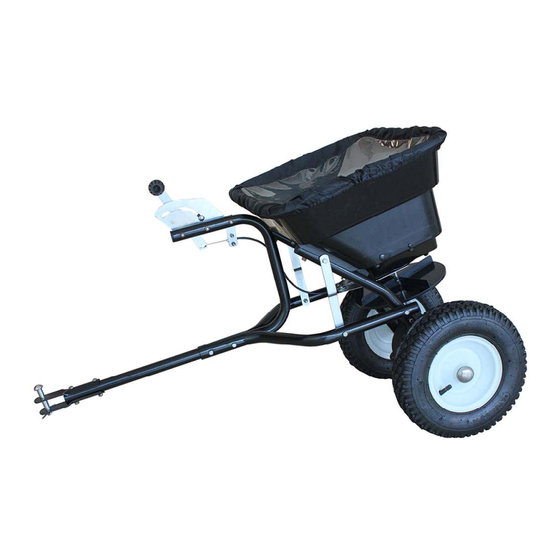
- Page 1 80LB TOW-BEHIND SPREADER Instruction & Assembly SAVE THESE INSTRUCTIONS FOR FUTURE REFERENCE REV150120...
-
Page 2: Safety Rules
SAFETY RULES READ THE DIRECTIONS BEFORE ASSEMBLY Read the towing vehicle owners manual and towing vehicle safety rules. Know how to operate your tractor before using the tow-behind spreader. Read the chemical label instructions and cautions for handling and applying the chemicals purchased for spreading. - Page 3 STEP1: Install Impeller onto the Gear Box & Axle Assembly. Insert Round Head Bolt M4x20 through impeller then through Gear Box Axle.
- Page 4 STEP 2: Attach the Wheel Assembly Frame on each side of the Gear Box Axle and Fixing Connecting Rod, insert two bolts M6x35 into the Fixing Connecting Rod through Wheel Assembly Frame. Make sure the hole on Axle of Gear Box is to be on the right side when assembly as shown. Attach Wheel Assembly Frames and Support Leg onto Hopper using bolts M6x45, lock nuts M6 and Big Flat Washers Ø6.
- Page 5 STEP 3: Install one end of the connecting plate on the wheel frame by Bolt M6x35 and Lock Nut M6. Then install the connecting rod on the wheel frame by Bolt M6x55 and Lock Nut M6 and fixed the connecting plate with connecting rod by Bolt M6x35.
- Page 6 STEP 4: Insert Inner Axle Bushing into Outer Axle Bushing and make sure they are tight neatly. Install right Wheel Assembly to right Axle using inner hex bolt M5x45 and lock nut M5, and then install the Cap onto right Axle using a wooden or rubber hammer.
- Page 7 STEP 5: Put the install tube assembly to hopper assembly using Bolt M6x40 and Lock Nut M6.NOW GO BACK AND TIGHTEN ALL NUTS AND BOLTS STARTING WITH FIRST STEP. DO NOT OVER TIGHTEN.
- Page 8 STEP 6: FINAL ADJUSTMENTS. When you finished all above steps, You don't need to do the following steps. If they are not match neatly, you may need to do the following steps. To operate this spreader, push the handle to the top position (upwards). You may move the position of Wing nut on Gauge & Lever to adjust the spacer of three holes between hopper and adjustable plate as per your need when spreading.
-
Page 9: General Warnings
GENERAL WARNINGS Operator must read and understand all safety and warning information, operating instructions, maintenance and storage instructions before operating this equipment. Failure to properly operate and maintain the lawn roller could result in serious injury to the operator or bystanders. Operation Warnings ... -
Page 10: Parts Drawing
PARTS DRAWING... -
Page 11: Parts List
PARTS LIST Part # Description Part # Description Carriage Bolt M6x25 R Pin Ø3 Tooth Washer Ø8 Lock Nut M6 Gauge & Lever Assembly Screw M5X12 Adjust Handle Pole Connect plate Adjust Handle A Bolt M6x55 Adjust Handle B Wheel Frame Assembly (Right) Screw M4x18 Pneumatic Wheel Hopper Screen... -
Page 12: Limited Warranty
Limited Warranty Warranty For one year from the date of purchase YTL International will replace for the original purchaser, or repair the push spreader. The warranty will not apply to any unit which was not assembled correctly, misused, overloaded or which has been used or operated contrary to our instructions, or which has been repaired or altered by anyone other than an authorized representative.
Need help?
Do you have a question about the YTL31507 and is the answer not in the manual?
Questions and answers