
Related Manuals for Big Joe PDBB-20-T12


Summary of Contents for Big Joe PDBB-20-T12
- Page 1 PDBB-20-T12 POWER DRIVE INTERMEDIATE LIFT TRUCK Serial Number 375067 and Higher Operation Maintenance Repair Parts List Big Joe Manufacturing Company • Des Plaines, IL 60018 MANUAL NO. 901357 Rev C, 12/08/06...
-
Page 3: Table Of Contents
TABLE OF CONTENTS Section Page Section Page 1 DESCRIPTION ............1-1 5-6. STEERING ARM RETURN SPRING 1-1. INTRODUCTION..........1-1 ADJUSTMENT..........5-4 1-2. GENERAL DESCRIPTION.......1-1 5-7. STEERING ARM RETURN SPRING 1-3. SAFETY FEATURES........1-2 REPLACEMENT..........5-4 5-8. PIVOT TUBE FLANGED BUSHING 2 OPERATION ...............2-1 REPLACEMENT. - Page 4 LIST OF ILLUSTRATIONS Figure Page Figure Page NAME PLATE ............. 1-1 10-4 CONTACTOR............ 10-4 PDBB-20-T12 LIFT TRUCK ........ 1-3 10-5 TRANSISTOR CONTROL ELECTRICAL SAMPLE OF OPERATOR CHECK LIST .... 2-3 CONTACTOR PANEL ........10-6 CONTROL HANDLE ........... 2-4 10-6 ELECTRICAL COMPONENTS......10-7 STEERING ARM BRAKING POSITION .....
- Page 5 LIST OF TABLES Table Page Table Page OPERATOR CHECKS ...........2-2 TROUBLESHOOTING CHART ......4-1 MONTHLY AND QUARTERLY INSPECTION AND FAULT RECOVERY EXCEPTIONS...... 4-4 SERVICE CHART ..........3-1 ADJUSTMENT SETTINGS........4-6 RECOMMENDED LUBRICANTS......3-3 LED CODES ............4-6 LUBRICATION DIAGRAM........3-4 TROUBLESHOOTING CHART ......4-7 LUBRICATION CHART ..........3-4 901357...
- Page 6 PREPARATION FOR USE Upon receipt, visually inspect the truck. If any damage Before the lift truck is moved, the battery must be is found, report it to the carrier and to your Big Joe checked, recharged if necessary, and connected. dealer immediately.
-
Page 7: Description
Drive is cutout when the platform is This publication describes the Power Drive Intermedi- raised above a preset limit. ate (PDBB-20-T12) lift truck manufactured by Big Joe Manufacturing Company, Des Plaines, Illinois, 60018. Included are operating instructions, planned mainte-... -
Page 8: Safety Features
1-3. SAFETY FEATURES. • Externally accessible quick-disconnect battery plug and an emergency power disconnect within opera- The PDBB-20-T12 is designed and engineered to pro- tor's reach. vide maximum safety for operator and payload. Some of the safety features incorporated into the design are: •... -
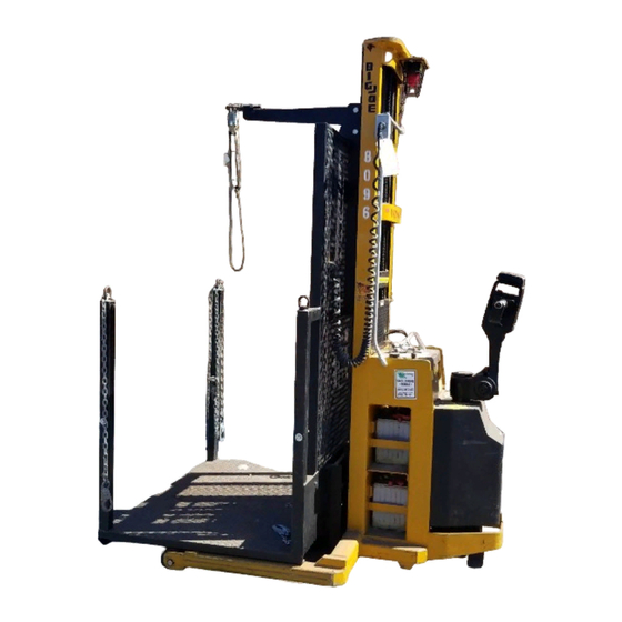
Page 9: Pdbb-20-T12 Lift Truck
R6214 Figure 1-2 PDBB-20-T12 LIFT TRUCK 901357... - Page 10 NOTES 901357...
-
Page 11: Operation
Table 2-1 covers important inspection points on on a regular basis. PDBB-20-T12 lift truck which should be checked prior • Be certain that required restraining means such as to operation. Depending on use, some trucks may safety belts, lifelines, and chains are properly used. -
Page 12: Operator Checks
Table 2-1 Operator Checks ITEM PROCEDURE ITEM PROCEDURE Travel controls Check that speed controls on Platform chains Verify that platform chains are control handle operate in all present and functional. speed ranges in forward and Flashing red light Verify that the flashing red light reverse and that belly button operates when the keyswitch is switch functions. -
Page 13: Sample Of Operator Check List
R6201 Figure 2-1 Sample of Operator Check List 901357... -
Page 14: Power Drive Control Handle
2-4.3. Driving and Stopping Procedures. The following procedure describes driving and stop- 2-4.1. Control Handle. ping the PDBB-20-T12 lift truck. Two triangular shaped speed controls provide for easy Turn the key switch to the on position. thumb actuation. Controls include an infinitely variable... -
Page 15: Belly-Button Switch Guard
R6203 Figure 2-3 Steering Arm Braking Position 2-5. BELLY-BUTTON SWITCH GUARD. Proceed as follows to raise and lower the platform. The belly-button switch guard minimizes the possibility If truck is equipped with a key switch, turn it to the of the driver being pinned by the steering arm while on position. - Page 16 NOTES 901357...
-
Page 17: Planned Maintenance
These procedures must be performed by Serial Number 375067 to 380099: Disconnect a qualified service technician or your Big Joe service the batteries from the truck and connect batteries representative. to the charger. Make sure connectors are mated properly. -
Page 18: Charge Indicator
The battery charger is fully automatic and will can be reset by switching the AC power to the cycle automatically (depending on amount of charger off. charge needed). Charge status can be observed The lower four red LED’s indicate current as follows (Refer to Figure 3-1):... -
Page 19: 3-3.3. Removing Batteries From Charger
100 SUS) foam suppressing agent and rust and oxidation inhibitors. 3-4. LUBRICATION. Refer to Table 3-2 for the recommended types of Big Joe Part No.900855 (1 gallon) grease and oil. Table 3-4 identifies the items requiring 900893 (1 quart) lubrication. -
Page 20: Lubrication Diagram
R6215 Table 3-3 Lubrication Diagram Table 3-4 Lubrication Chart FIG 3-3 LOCATION METHOD OF TYPE APPLICATION INDEX APPLICATION (Table 3-3) LUBRICANT Hydraulic System — No. 3 With lift carriage fully lowered, fill Capacity-6 quarts reservoir with hydraulic oil to "FULL" mark on dip stick. Platform rollers No. -
Page 21: Troubleshooting
SECTION 4 TROUBLESHOOTING 4-1. GENERAL Miscellaneous malfunctions. Refer to electrical wiring diagram (Figure 4-2 Figure 4-5) as a supplement to Table 4-1 serves as a guide to determine possible the troubleshooting chart or when tracing an electri- causes of trouble. The table is divided into five main cal circuit. - Page 22 Table 4-1 Troubleshooting Chart - Continued MALFUNCTION PROBABLE CAUSE CORRECTIVE ACTION Weak, slow or uneven action of a. Defective pump. Check pressure. hydraulic system. b. Defective lift cylinder. Clean system and valve. c. Load larger than capacity. Refer to name plate on side of mast for maximum load capacity.
-
Page 23: Gel Cell Battery Charger 004987 Troubleshooting
4-2. GEL CELL BATTERY CHARGER 004987 Verify 25 VAC from blue wire to each white TROUBLESHOOTING wire. Refer to Figure 4-2, Figure 4-3, Figure 4-4 for part Verify 50 VAC from the white wire to white identification. Be sure the batteries are connected to wire. -
Page 24: Transistor Controller Troubleshooting
The programmer (Part Number 005472-02) When a fault is detected, the appropriate fault code is is available through your Big Joe dealer. If you require signaled via the LED, externally visible on the side of dealer location information contact Big Joe Manufac-... -
Page 25: 4-3.5. General Checkout
4-3.5. General Checkout. ward/reverse contactors, and motor. The motor should run proportionally faster with increasing Carefully complete the following checkout procedure. throttle. If not, refer to Paragraph 4-3.7. If you find a problem during the checkout, refer to Paragraph 4-3.7. for further information. -
Page 26: 4-3.7. Diagnostics And Troubleshooting
Table 4-3. Adjustment Settings 4-3.7.1. LED Diagnostics During normal operation, with no faults present, the Function Setting Status LED flashes a single flash at approximately 1 Creep Speed flash/second. If the controller detects a fault, a 2-digit Mode 1 Plugging Current Limit Not Used fault identification code is flashed continuously until Mode 1 Acceleration Rate... -
Page 27: Troubleshooting Chart
4-3.7.2. Programmer Diagnostics The following 4-step process is generally used for diagnosing and troubleshooting an inoperative vehicle: With a programmer, diagnostics and troubleshooting is (1) visually inspect the vehicle for obvious problems; more direct than with the LED alone. The programmer (2) diagnose the problem, using the programmer;... -
Page 28: Troubleshooting Chart
Table 4-5. Troubleshooting Chart (Continued) LED CODE PROGRAMMER EXPLANATION POSSIBLE CAUSE LCD DISPLAY CONT DRVR OC driver output overcurrent 1. Direction contactor coil shorted. 2. Shunt field shorted. DIR CONT WELDED welded direction contactor 1. Direction contactor stuck closed. MISSING CONTACTOR missing contactor or shunt 1. - Page 29 NOTES 901357...
-
Page 30: Wiring Diagram (Sheet 1)
USED ON TRUCKS SERIAL NUMBERS 375067 TO 379100, 379105 TO 379110, 379112 TO 379133, 379135 TO 179138, 379141 TO 379147, 379183 TO 379186 RMT CONTROL RMT CONTROL LOWERING STATION BUZZER DOWN STOP PLATFORM PLUG RECPT. E.P.D. ENCLOSURE E.P.D. ENCLOSURE ENGAGEMENT N.C. - Page 31 USED ON TRUCKS SERIAL NUMBERS 375067 TO 379100, 379105 TO 379110, 379112 TO 379133, 379135 TO 179138, 379141 TO 379147, 379183 TO 379186 REVERSING HORN REVERSE N.C. N.O. N.O. N.C. N.O. 5K SPEED CONTROL 5K SPEED CONTROL N.C. FORWARD POTENTIOMETER 1.2 K 1.2 K 12 11...
- Page 32 USED ON TRUCKS SERIAL NUMBERS 379101 TO 379104, 379111, 379134, 379139 TO 379140, 379148 TO 379182, 379187 TO 280099 RMT CONTROL RMT CONTROL LOWERING STATION BUZZER DOWN STOP PLATFORM E.P.D. ENCLOSURE E.P.D. ENCLOSURE ENGAGEMENT SWITCH N.C. COM N.C. N.O. DEADMAN NO NC N.O.
- Page 33 USED ON TRUCKS SERIAL NUMBERS 379101 TO 379104, 379111, 379134, 379139 TO 379140, 379148 TO 379182, 379187 TO 280099 REVERSING REVERSE HORN N.C. N.O. N.O. N.C. N.O. 5K SPEED CONTROL 5K SPEED CONTROL N.C. POTENTIOMETER FORWARD 1.2 K 1.2 K 1211 CONTROL HEAD CONTROL HEAD...
- Page 34 USED ON TRUCKS SERIAL NUMBERS 380100 AND HIGHER R6492A Figure 4-4 Wiring Diagram (Sheet 1) 4-14 901357...
- Page 35 USED ON TRUCKS SERIAL NUMBERS 380100 AND HIGHER R6492B Figure 4-4 Wiring Diagram (Sheet 2) 901357 4-15...
-
Page 36: Electrical Schematic (Sheet 1)
R6205A Figure 4-5 Electrical Schematic (Sheet 1) 4-16 901357... - Page 37 R6205B Figure 4-5 Electrical Schematic (Sheet 2) 901357 4-17...
- Page 38 NOTES 4-18 901357...
-
Page 39: Steering Arm, Control Head And Pivot Tube Servicing
SECTION 5 STEERING ARM, CONTROL HEAD AND PIVOT TUBE SERVICING 5-1. GENERAL. Being careful to catch and retain the belly-button springs (4, Figure 5-2) that may fall from the con- The following procedures cover adjustments, replace- trol head (9) as the belly-button casting (1) is ment, and repair of the steering arm, control head, and removed, drive out the roll pins (2) that secure the related assemblies and components. -
Page 40: Control Head Assembly
R6182 Figure 5-2 Control Head Assembly 901357... -
Page 41: Potentiometer Testing And Adjustment
5-3. Potentiometer Testing and Adjustment 5-4. CONTROL HEAD SWITCH REPLACEMENT. Disconnect the battery NOTE: Refer to paragraph 5-5. for speed control switch replacement. Remove screws (17 and 58, Figure 5-2) and access covers (16 and 57). NOTE: For access to belly-button switch, see para- Check gap between rollers on directional switches graph 5-2. -
Page 42: Steering Arm Return Spring Adjustment
Remove roll pin (50) from right hand handle grip Hold the steering arm (10, Figure 5-4) in the (49). upright position and make sure the arm cannot fall. 10. Remove right hand handle grip from shaft (48). Insert a 5/16 allen wrench through hole in bottom 11. -
Page 43: Steering Arm And Electrical Cable
With a pair of vise-grip pliers, grip the flat surfaces 10. Slide spring tube assembly into pivot cap (14) and of spring tube assembly (4), and slowly pull it free steering arm (10) through tube clamp (13) and from the steering arm, pivot cap and tube clamp through loop of electrical cable. -
Page 44: Pivot Tube Flanged Bushing Replacement
5-8. PIVOT TUBE FLANGED BUSHING Remove four nuts (9, Figure 5-5), four lock wash- REPLACEMENT. ers (8), ring (7) and pivot tube guide (6). NOTE: Replacement of the pivot tube and flanged NOTE: When installing the new pivot tube guide (6), bushing requires the removal of the steering refer to Figure 5-5... -
Page 45: Electrical Control Cable Replacement
5-9. ELECTRICAL CONTROL CABLE REPLACE- 16. Connect the new cable connector (9) to the con- MENT. nector on the electrical control panel. 17. Route and connect cable wire number 7 to the NOTE: Refer to Figure 5-6 while performing the fol- horn. - Page 46 R6212 Figure 5-6 Electrical Control Cable Replacement 901357...
-
Page 47: Brake Servicing
SECTION 6 BRAKE SERVICING 6-1. DEADMAN SWITCH ADJUSTMENT 6-2. DEADMAN SWITCH REPLACEMENT If the electrical brake does not engage when the steer- Disconnect battery connections. ing arm is raised or lowered into the shaded area in Remove pivot cap cover (4, Figure 6-3). -
Page 48: Brake And Actuator
R6185 Figure 6-2 Brake and Actuator 901357... -
Page 49: Pivot Tube And Transmission Assembly
R6184 Figure 6-3 Pivot Tube and Transmission Assembly 901357... -
Page 50: Electric Brake
6-3. ELECTRIC BRAKE Finally tighten bolts (4) and recheck the gap as described in step The electric brake is spring applied, electrically disen- gagned. The brake can be adjusted for normal wear or the rotor can be replaced. 6-3.1. Brake Adjustment Serial Number 376500 to 377143 NOTE: Adjustment of the brake requires the removal... -
Page 51: 6-3.3. Removal
Check truck for proper operation before returning Reinstall the pivot tube (23, Figure 6-3) onto the to service. transmission/motor/brake assembly (18) and secure with four screws (21) and four lock wash- 6-3.3. Removal ers (22). Reinstall the pivot tube with transmission/motor/ NOTE: Adjustment of the brake requires the removal brake assembly as described in SECTION... - Page 52 NOTES 901357...
-
Page 53: Transmission, Drive Wheel, And Load Wheel Servicing
SECTION 7 TRANSMISSION, DRIVE WHEEL, AND LOAD WHEEL SERVICING 7-1. DRIVE WHEEL REMOVAL. Disconnect battery. Block load wheels securely. Raise the rear of the truck using jacks or other suitable means so that drive wheel is off the floor. Disconnect the electrical control cable from the electrical control panel. - Page 54 R6184 Figure 7-3 Pivot Tube and Transmission Assembly 901357...
-
Page 55: Transmission, Motor And Brake Assembly Installation
12. Remove screw (19, Figure 7-3) with lock washer Slowly raise the pivot tube with transmission, (16) from transmission (18). being careful to check for alignment with the pivot tube guide (6) and bracket (10). 13. Remove nut (20), screw (17), and two lock wash- ers (16). -
Page 56: Load Wheels
7-4. LOAD WHEELS. NOTE: Refer to Figure 7-4 for the following proce- dure. Block the caster wheels and remaining load wheel securely, and set the brakes. Raise front end of lift truck with a jack or another lift truck. Place strong supports under straddle leg immediately in back of wheel housing so that the load wheel being replaced is held approximately one inch from the floor. -
Page 57: Elevation System Servicing
SECTION 8 ELEVATION SYSTEM SERVICING 8-1. GENERAL. feet from floor and position blocks or strong sup- ports under inner mast (4, Figure 8-1). The elevation system includes the outer mast, inner Lower platform until it is supported by the block mast, platform, lift chains, lift cylinder, and ram head. -
Page 58: Elevation System
R6189 Figure 8-1 Elevation System 901357... -
Page 59: Ram Head Removal
WARNING: Before disconnecting any hydraulic line, With the lift truck wheels securely blocked and be sure the system is not under pres- with brake set, raise platform approximately three sure. feet from floor and position blocks or strong sup- ports under inner mast (4, Figure 8-1). - Page 60 NOTES 901357...
-
Page 61: Hydraulic System Servicing
SECTION 9 HYDRAULIC SYSTEM SERVICING 9-1. RELIEVING SYSTEM PRESSURE. 9-2. FLOW CONTROL VALVE REPLACEMENT. WARNING: Hydraulic system pressure must be NOTE: Figure 9-1 show the relationship of all compo- relieved before removing hydraulic sys- nents in the hydraulic system. Refer to these tem components. -
Page 62: Suction Line Filter Replacement
Hydraulic oil can dissolve the battery 13. Check oil level on dip stick. If low, fill to ``FULL'' case. Wipe off any spilled oil immedi- mark on dip stick with Big Joe hydraulic oil Part ately. Number 900855. Remove the reservoir drain plug and drain the 14. -
Page 63: Hydraulic Pump And Motor Assembly
9-5. HYDRAULIC PUMP AND MOTOR ASSEMBLY. Turn the screwdriver clockwise to increase hydraulic pressure; counterclockwise to decrease A defective hydraulic pump must be replaced as a pressure. complete unit, but the pump motor can be repaired Install the cap nut on the hydraulic pump. (see SECTION 10, Electrical Components Servicing. - Page 64 PACKING KIT PART NUMBER 907123 CONTAINS: ITEM R5812 Figure 9-2 Lift Cylinder 901357...
-
Page 65: Electrical Components
SECTION 10 ELECTRICAL COMPONENTS 10-1.BATTERIES. NOTE: Batteries are heavy. Use care when sliding out of battery compartment. NOTE: Batteries are removed from the right side of the truck. When installing a new battery, be Remove screw (19), washer (21) and retainer bar sure handles are securely fastened to battery, (22). -
Page 66: Batteries And Emergency Power Disconnect
USED ON TRUCKS SERIAL NUMBERS 380100 AND HIGHER R6493 Figure 10-2 Batteries and Emergency Power Disconnect 10-2 901357... -
Page 67: Emergency Power Disconnect
10-2.EMERGENCY POWER DISCONNECT Make sure the connections to the bus bars are tight. Use two well insulated wrenches for this The emergency power disconnect is located in front of task in order to avoid stressing the bus bars. the steering arm as shown in Figure 10-1 Figure 10- 2. -
Page 68: Emergency Power Disconnect
R5770 Figure 10-3. Emergency Power Disconnect R5771 Figure 10-4. Contactor 10-4 901357... - Page 69 10-3.4.Test the Fault Detection Circuitry 10-5.DRIVE MOTOR. Put the vehicle up on blocks to get the drive wheel Refer to Figure 11-19 for motor disassembly. off the ground. 10-6.BATTERY CHARGER. Disconnect the battery and make sure the key- switch is off. Refer to Figure 11-24 thru...
-
Page 70: Transistor Control Electrical Contactor Panel
R6199 Figure 10-5. Transistor Control Electrical Contactor Panel 10-6 901357... -
Page 71: Electrical Components
R6448 Figure 10-6 Electrical Components 901357 10-7... - Page 72 NOTES 10-8 901357...
-
Page 73: Illustrated Parts Breakdown
SECTION 11 ILLUSTRATED PARTS BREAKDOWN Following is an illustrated parts breakdown of assemblies and parts associated with the PB-PDBB-20-T12 Lift Truck. 901357 11-1... - Page 74 R6182 Figure 11-1 Control Head Assembly 11-2 901357...
- Page 75 INDEX PART INDEX PART PART NAME REQD. PART NAME REQD. 072400-01 SLOTTED HEX SCREW, — 505360-01 CONTROL HEAD STANDARD 6-32 X 1/2 800274 COVER 077204 SPLIT LOCK WASHER #6 061016 ROLL PIN, 1/4 X 3 077007 WASHER 402843 069478 PHILIPS FLAT HD SCREW, 075510 COMPRESSION SPRING 1/4-20 X 3/4...
- Page 76 HANDLE RETURN SPRING PART NUMBER 901325 CONTAINS: ITEM R6183 Figure 11-2 Steering Arm INDEX PART INDEX PART PART NAME REQD. PART NAME REQD. — 071377 . SCREW, 10-32 X 3/4 506244-01 CONTROL ARM ASSY 800275 . HANDLE 065569 . SCREW, 7/16-14 X 2-1/4 285302 * .
- Page 77 R6184 Figure 11-3 Pivot Tube Assembly INDEX PART INDEX PART PART NAME REQD. PART NAME REQD. 067443-02 SCREW, HHC, METRIC, M10 X 45 — CONTROL HEAD (FIGURE 11-1) 077212 WASHER, LOCK, 7/16 065481 SCREW, SOC HD, 1/4-20 X 1 067443-03 SCREW, HHC, METRIC, M10 X 65 —...
- Page 78 R6185 Figure 11-4 Brake and Actuator 11-6 901357...
- Page 79 INDEX PART INDEX PART PART NAME REQD. PART NAME REQD. 506199 BRACKET ASSY, SWITCH 023238-29 WIRE ASSY (FIGURE 11-16) MOUNTING 021249 TERMINAL, SLIP ON, 3/16 020775 SWITCH, DEADMAN 005422 SPLICE, BUTT, CRIMP 059634 NUT, HEX, NYLOK, 4-40 023238-30 WIRE ASSY (FIGURE 11-16) 065451...
- Page 80 R6208 Figure 11-5 Transmission, Motor and Brake Assy INDEX PART INDEX PART PART NAME REQD. PART NAME REQD. 901783 . O-RING, 65 X 2,5 — 506162 TRANSMISSION, MOTOR AND BRAKE ASSY 901784 . KEY, WOODRUFF, 3 X 5 901775 . ELECTRIC BRAKE 901785 .
- Page 81 R6187 Figure 11-6 Base and Frame INDEX PART INDEX PART PART NAME REQD. PART NAME REQD. 059421 NUT, HEX, 1/4-20 506200 COVER, WELDMENT 504579 SCREEN 070476 SCREW, RD HD, 1/4-20 X 1/2 057511 GROMMET, 077209 WASHER, SPLIT, LOCK, 1/4 1-1/2” ID X 1-34” HOLE 077031 WASHER, FLAT NO.
- Page 82 DECAL KIT PART NUMBER 901774 CONTAINS: ITEM R6190 Figure 11-7 Decal Location INDEX PART INDEX PART PART NAME REQD. PART NAME REQD. 056590 WARNING DECAL 056595 CASTING LOGO 056644 TRUCK-CHARGE DECAL 056596-08 INSERT PDI 056646 INSTR-CHARGER 20574 EPD DECAL 061334 NAMEPLATE 056654 NOTICE DECAL...
- Page 83 LOAD WHEEL AND AXLE KIT PART NUMBER 901326 CONTAINS: ITEM R6188 Figure 11-8 Load Wheels INDEX PART INDEX PART PART NAME REQD. PART NAME REQD. 060974* . PIN, ROLL — — LOAD WHEEL 025713* . GREASE FITTING 061725* . SNAP RING 270306* .
- Page 84 R6189 Figure 11-9 Elevation System 11-12 901357...
- Page 85 INDEX PART INDEX PART PART NAME REQD. PART NAME REQD. 060402 COTTER PIN 402034 CHAIN (7.76 FT EACH) — PLATFORM (FIGURE 11-10) 053000 SHIM 077215 WASHER, LOCK 053001 SHIM 059445 NUT, HEX 053002 SHIM 402051 ADJUSTING BOLT 053003 SHIM 059545 NUT, JAM, 5/8-18 901366 ROLLER ASSEMBLY...
- Page 86 R6191 R6192 Figure 11-10 Platform INDEX PART INDEX PART PART NAME REQD. PART NAME REQD. 059444 . NUT, HEX, 5/8-11 — 506242 PLATFORM, CARRIAGE AND BOOM ASSY 074602 ROPE SNAP 20538 . PLATFORM, WELDMENT 074603 COLD SHUT — . BOOM ASSY (FIGURE 11-11) 055628...
- Page 87 R6193 Figure 11-11 Boom, Self Retracting Lifeline And Safety Belt INDEX PART INDEX PART PART NAME REQD. PART NAME REQD. 059637 . NUT, NYLOCK, 1/2-13 — 506195 BOOM ASSY. 059426 . NUT, HEX, 5/16-18 506194 . BOOM WELDMENT 074011-01 SELF RETRACTING LIFELINE 404282 .
- Page 88 R6194 Figure 11-12 Hydraulic System 11-16 901357...
- Page 89 INDEX PART INDEX PART PART NAME REQD. PART NAME REQD. 20594 SHEATH, HOSE 506264 RESERVOIR ° 025116 ELBOW, 90 , SWIVEL 1/4 NPT — PUMP & MOTOR (FIGURE 11-20) 282500 TUBING, VINYL, 1/4” OD X 0.180” ID 048133 SOLENOID VALVE, LOWERING 504578 BREATHER &...
- Page 90 PACKING KIT PART NUMBER 907138 CONTAINS: ITEM R5812 Figure 11-13 Lift Cylinder INDEX PART INDEX PART PART NAME REQD. PART NAME REQD. 400860 . RAM STOP — 503604 HYD. LIFT CYLINDER ASY 042105 * . BOTTOM O-RING 503609 . TUBE 800293 * .
- Page 91 NOTES 901357 11-19...
- Page 92 USED ON TRUCKS SERIAL NUMBERS 375067 TO 380099 R6197 Figure 11-14 Batteries 11-20 901357...
- Page 93 INDEX PART INDEX PART PART NAME REQD. PART NAME REQD. 504608 BATTERY CONNECTOR ASSY — HYD RESERVOIR (FIGURE 11-12) 077031 WASHER, FLAT — EPD CONTACTOR ASSY 059421 NUT, HEX, 1/4-20 (FIGURE 11-22) 077209 WASHER, LOCK, 1/4 077031 WASHER, FLAT 402258 CHANNEL 077209 WASHER, LOCK, 1/4...
- Page 94 USED ON TRUCKS SERIAL NUMBERS 380100 AND HIGHER R6493 Figure 11-15 Batteries 11-22 901357...
- Page 95 INDEX PART INDEX PART PART NAME REQD. PART NAME REQD. 402258 CHANNEL — HYD RESERVOIR (FIGURE 11-12) 056128 SPIROBAND — EPD CONTACTOR ASSY 504609 CABLE ASSY (FIGURE 11-22) 063478 SCREW, HEX CAP, 1/4-20 X 3/4 077031 WASHER, FLAT 504608 BATTERY CONNECTOR ASSY 077209 WASHER, LOCK, 1/4 077209...
- Page 96 R6448 Figure 11-16 Chassis Mounted Electrical Components 11-24 901357...
- Page 97 INDEX PART INDEX PART PART NAME REQD. PART NAME REQD. 063553 SCREW, HHC, 5/16-18 X 3/4 20624 WIRE HARNESS 056135 CLAMP, LOOP, CUSHIONED 021203 TERMINAL, RING 077210 WASHER, LOCK, SPLIT, 5/16 023238-14 WIRE ASSY 063553 SCREW, HHC, 5/15-18 X 3/4 505921 SUPPRESSOR, SOLENOID 020725...
- Page 98 USED ON TRUCKS SERIAL NUMBERS 375067 TO 379100, 379105 TO 379110, 379112 TO 379133, 379135 TO 179138, 379141 TO 379147, 379183 TO 379186 R6198 Figure 11-17 Platform Mounted Electrical Components 11-26 901357...
- Page 99 INDEX PART INDEX PART PART NAME REQD. PART NAME REQD. 013610 GUADE, LAMP 059421 NUT, HEX, 1/4-20 071376 SCREW, TRUS, #10-32 X 1/2 800257 CLAMP, HALF 063480 SCREW, HEX CAP, 1/4-20 X 1 056113 TIE, WIRE, NYLON, 6-3/8” 077031 WASHER 056111 TIE, WIRE, NYLON, 4”...
- Page 100 USED ON TRUCKS SERIAL NUMBERS 379101 TO 379104, 379111, 379134, 379139 TO 379140, 379148 TO 379182, 379187 AND HIGHER R6449 Figure 11-18 Platform Mounted Electrical Components 11-28 901357...
- Page 101 INDEX PART INDEX PART PART NAME REQD. PART NAME REQD. 013610 GUADE, LAMP 059421 NUT, HEX, 1/4-20 071376 SCREW, TRUS, #10-32 X 1/2 800257 CLAMP, HALF 063480 SCREW, HEX CAP, 1/4-20 X 1 056113 TIE, WIRE, NYLON, 6-3/8” 077031 WASHER 056111 TIE, WIRE, NYLON, 4”...
- Page 102 I7022 Figure 11-19 Drive Motor INDEX PART INDEX PART PART NAME REQD. PART NAME REQD. 901728 . BEARING, COMMUTATOR END — 016051 MOTOR, DRIVE 901729 . BRUSH BOX ASSEMBLY 901722 . CLIP, SPRING 901730 . SPRING, BRUSH (SET OF 901723 .
- Page 103 OUTPUT PORT INLET PORT R6025 R6036 016940 PDI CONFIGURATION Figure 11-20 Hydraulic Pump and Motor Assembly INDEX PART INDEX PART PART NAME REQD. PART NAME REQD. 906006 . COUPLING — 016940 PUMP AND MOTOR ASSY 906007 . MOTOR ASSY 906003 .
- Page 104 R6199 Figure 11-21 Electrical Control Panel 11-32 901357...
- Page 105 INDEX PART INDEX PART PART NAME REQD. PART NAME REQD. 059526 . NUT, HEX, JAM, 5/16-18 — 506240 ELECTRICAL PANEL ASSEMBLY 504611-45 CABLE ASSY, #6 (CONTL A2 TO 404321 . BRACKET, ELECT PANEL REV CONTR) 005468 . CONTROLLER, TRANSISTER, 504611-37 CABLE ASSY, #6 (CONTL B- TO 250A, 24V PUMP MTR NEG)
- Page 106 R5770 Figure 11-22 Emergency Power Disconnect INDEX PART INDEX PART PART NAME REQD. PART NAME REQD. 059412 . . NUT-HEX, 6-32 20798 CONTACTOR ASSY-EPD (WITH EXTERNAL CABLES & 077204 . . WASHER-LOCK, SPLIT, #6 BATTERY CONNECTOR - SEE 077007 . . WASHER FIGURE 11-21) 067416...
- Page 107 R5771 Figure 11-23 Contactor INDEX PART INDEX PART PART NAME REQD. PART NAME REQD. 903169 . MOVABLE TIP CARRIER 903176 CONTACTOR 903172 . PLUNGER BUSHING 903206 . BUS BASE 903208 . CONTACT SPACER — . NUT 903179 . BUS ASSEMBLY —...
- Page 108 USED ON TRUCKS SERIAL NUMBERS 375067 TO 375260 R6118 Figure 11-24 Gel Cell Battery Charger INDEX PART INDEX PART PART NAME REQD. PART NAME REQD. 505992 BRACKET, CHARGER — 004987 CHARGER KIT-24V, 25 AMP 077209 WASHER-LOCK, SPLIT, 1/4 904075 . PCB ASSY WITH HEATSINK 077421 NUT-HEX, 1/4-20 904074...
- Page 109 USED ON TRUCKS SERIAL NUMBERS 375261 TO 380099 R6216 Figure 11-25 Gel Cell Battery Charger Installation INDEX PART INDEX PART PART NAME REQD. PART NAME REQD. 077210 WASHER, LOCK, SPLIT, 5/16 23884 CORD ASSY - BREAK-A-WAY 059426 NUT, HEX, 5/16-18 056685 .
- Page 110 USED ON TRUCKS SERIAL NUMBERS 375261 TO 380099 R6217 Figure 11-26 Gel Cell Battery Charger INDEX PART INDEX PART PART NAME REQD. PART NAME REQD. 077032 WASHER, 3/16 X 1/2 X 13 GA — 506320-03 CHARGER-24V, 25 AMP 023238-27 WIRE ASEMBLY 904075 .
- Page 111 USED ON TRUCKS SERIAL NUMBERS 380100 AND HIGHER R6494 Figure 11-27 Gel Cell Battery Charger Installation INDEX PART INDEX PART PART NAME REQD. PART NAME REQD. 077210 WASHER, LOCK, SPLIT, 5/16 23884 CORD ASSY - BREAK-A-WAY 059426 NUT, HEX, 5/16-18 056685 .
- Page 112 USED ON TRUCKS SERIAL NUMBERS 380100 AND HIGHER R6495 Figure 11-28 Gel Cell Battery Charger INDEX PART INDEX PART PART NAME REQD. PART NAME REQD. 077031 WASHER, 5/16 X 3/4 X 16 GA — 506320-03 CHARGER-24V, 25 AMP 077032 WASHER, 3/16 X 1/2 X 13 GA 904075 .
- Page 114 Big Joe Manufacturing Company...
Need help?
Do you have a question about the PDBB-20-T12 and is the answer not in the manual?
Questions and answers
I **** trying to find the part number, or place to get the charger cord for the PDBB20-12 Big Joe Lift
The charger for the Big Joe PDBB-20-T12 Lift is listed as part number 506320-03, described as "CHARGER-24V, 25 AMP." However, a specific charger cord is not listed separately in the provided parts list. It may be included with the charger assembly.
This answer is automatically generated