Table of Contents
Advertisement
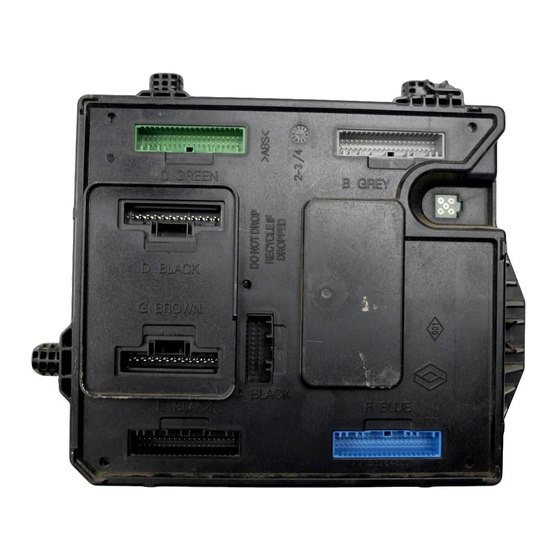
Engine and peripherals
1
ENGINE AND CYLINDER BLOCK ASSEMBLY
10A
TOP AND FRONT OF ENGINE
11A
FUEL MIXTURE
12A
12B
13A
13B
13C
14A
16A
17A
17B
"The repair methods given by the manufacturer in this document are based on the technical
specifications current when it was prepared.
The methods may be modified as a result of changes introduced by the manufacturer in the
production of the various component units and accessories from which his vehicles are
constructed."
X95, and F4R or F9Q or K4M or K9K
JUNE 2008
© Renault s.a.s 2008
All copyrights reserved by Renault.
The reproduction or translation in part of whole of the present document, as well as the use
of the spare parts reference numbering system, are prohibited without the prior written
consent of Renault.
Edition Anglaise
Advertisement
Table of Contents


Need help?
Do you have a question about the F4R and is the answer not in the manual?
Questions and answers