
Subscribe to Our Youtube Channel
Related Manuals for Country Clipper PBSD


Summary of Contents for Country Clipper PBSD
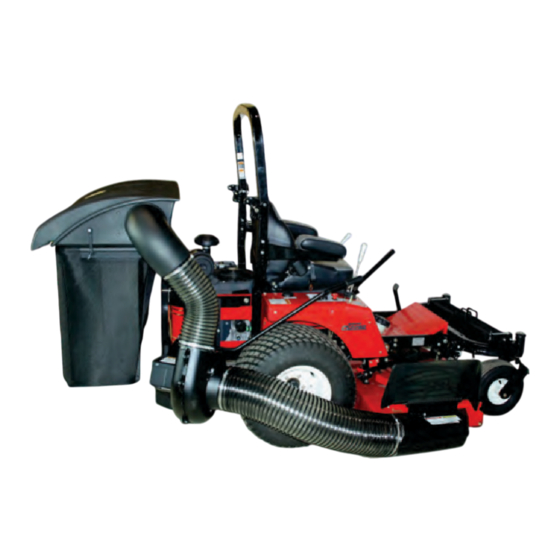
- Page 1 PROFESSIONAL BAGGING SYSTEM MODEL# PBSD (49131502) DESIGNED FOR THE DEFENDER & BOSS XL SERIES OPERATOR’S MANUAL ASSEMBLY OPERATION MAINTENANCE MANUAL#: Q0478 PART# 629GR-001A Revision 4.0 - 6/18/2018...
-
Page 2: Table Of Contents
PROFESSIONAL BAGGING SYSTEM TABLE OF CONTENTS SECTION PAGE SECTION PAGE Safety - - - - - - - - - - - - - - - - - - - - - - - - - - - - - - 2 2-15 Boot To Mower Deck Installation - - - - - - - - - - - 14 Safety Alert Symbols - - - - - - - - - - - - - - - - - - - - - - 3 2-16 Length Of Hose Adjustment - - - - - - - - - - - - - - 15... -
Page 3: Safety Alert Symbols
SAFETY WARNING! NEVER operate the mower unless the discharge guard and either the deflector assembly or the vacuum collector adapter are fastened securely in place. WARNING! Do not work around the mower deck boot or the blower area until you are certain that the mower blades and the blower impeller have stopped rotating. -
Page 4: Warranty
H. REMEDIED EXCLUSIVE. The only remedies the purchaser has in connection with the breach or performance of any warranty on Country Clipper bagging systems are set forth above. In no event will Country Clipper be liable for special incidental or consequential damages. -
Page 5: Introduction And Description
Remove deck drive belt from the clutch pulley (refer to Use engine pulley assembly #24 P#(A1176), (1) 7/16” your Country Clipper operator’s manual). From the lock washer P#(K0140), and 7/16”-20 x 4-1/2” hex bolt underside of the engine, disconnect the wiring harness P#(K0427). -
Page 6: Upper And Lower Rear Frame Bracket Installation
2-2 Upper And Lower Rear Frame Bracket Installation Remove the front step and mounting hardware from the front caster assembly. Reference your Country Clipper First, remove (2) existing top bolts 3/8”-16 x 1” FHCS owner’s manual and Figure 2-1e. and (2) 3/8”-16 nyloc nuts that secure the top rear engine guard bar. -
Page 7: Pto Mount Plate Component Installation
2-3 PTO Mount Plate Components Installation Remove the (2) existing 1/2”-13 x 2” FHCS and (2) 1/2”-13 nyloc nuts from the top and bottom rear engine guard bars (shown in Figure 2-3a). Secure the Left PTO mount plate P#(B0852) using the existing hardware. Figure 2-3a (1) Existing 1/2”-13... -
Page 8: Pto Assembly Installation
2-4 PTO Assembly Installation 2-5 PTO Handle Installation To mount the PTO assembly, insert the pivot rod on the Attach the PTO handle P#(A1142) to the PTO assembly PTO assembly P#(A1950) into the mounting slots using (3) 1/4”-20 x 3/4” HHCS P#(K1222) and (3) 1/4”- located on the left &... -
Page 9: Belt Installation And Adjustment
Connect the belt A57K P#(M0256) from the engine 2-6 Belt Installation and Adjustment pulley to the lower gear box pulley (Figure 2-6d). PTO MODELS ONLY Figure 2-6d Loosen the (4) bolts P#(K1191), (2) on each side, that Connect Belt secure the gear box assembly to the PTO assembly To Both Pulleys P#(A1950) (Figure 2-6a and 2-6b). -
Page 10: Cam Assembly Adjustment
2-7 Cam Assembly Adjustment 2-8 Blower Cone Installation Thread (1) 5/16”-18 jam nut P#(K0120) onto each end of The cam assembly P#(A0422), which controls the (2) 5/16”-18 x 2-1/2” HHCS P#(K0125) as shown in blower belt tension, comes from the factory pre-adjusted. Figure 2-8a. -
Page 11: Lower Mount Tube Installation
2-9 Lower Mount Tube Installation Secure the (2) lower mount tubes P#(B0640) to the rear lower and upper frame brackets using (2) 5/16”-18 x 2-1/4” u- bolts P#(K1098) and (4) 5/16”-18 nylon flange locknuts P#(K2516) PER TUBE. The bottom edge of the lower mount tubes should be flush with the bottom flange of the rear lower frame bracket. Refer to Figure 2-9. -
Page 12: Upper Frame Assembly Installation
2-10 Upper Frame Assembly 2-11 Top Assembly To Upper Frame Installation Assembly Installation Position the top assembly P#(A1190) above the upper NOTE: During this step, it is suggested that two people frame assembly as shown in Figure 2-10. Fasten the top install the upper frame to the lower mount tube. -
Page 13: Rops Pivot Bracket Installation
2-13 ROPS Pivot Bracket Installation To allow the ROPS to fold down without hitting the bagger top, insert a total of (4) B0872 - ROPS Pivot Brackets, (2) per side with arrow aligned as shown in Figure 2-13a. When folding the ROPS is desired, pin the ROPS as shown in Figure 2-13b. -
Page 14: Boot Plate Installation
2-14 Boot Plate Installation 2-15 Boot To Mower Deck Installation Secure the boot plate P#(B0820) to the aluminum boot Remove the hardware from the grass deflector and P#(E1902) using (2) 3/8”-16 x 1” carriage bolts insert (1) boot rod P#(B4331) into the grass deflector P#(K1182) and (2) 3/8”-16 nylon flange locknuts mounting holes as shown in Figure 2-13a. -
Page 15: Length Of Hose Adjustment
2-16 Length Of Hose Adjustment 2-18 Lower Hose To Blower Cone Installation The hoses in steps 2-17 and 2-18 must be cut to fit your machine. Follow steps 2-17 and 2-18. Do not cut the Slide a hose clamp P#(J0080) over both ends of hoses until you have tried to fit them on your machine. -
Page 16: Impeller Blade Removal/Replacement
2-20 Impeller Blade Removal/Replacement To gain impeller blade (#1) access, first remove the Tips on removing impeller blade; blower cone (#2) from the blower housing, located on 1 - Try carefully hitting the base of the impeller blade the PTO assembly P#(A1821), by removing two blower (#1), between each vein (#12), with a rubber mallet to loosen the taper-lock bushing hold. -
Page 17: Front Weight Installation
Weight Kit Installation Position the Dual Weight Bracket Base (Item#1) under the caster tubing w/ opening towards caster fork. Next, position the Weight Bracket Clamp (Item#2) on top of caster tubing w/ opening towards caster fork. Align the (4) holes of the Weight Bracket Clamp (Item#2) to the holes in the Dual Weight Bracket Base (Item#1). Loosely fasten the Weight Bracket Clamp (Item#2) to the Weight Bracket Base (Item#1) using (4) 5/16"-18 x 3"... -
Page 18: Installation And Removal Of Collection Bags
2-23 Installation/Removal Of Figure 2-22c Collection Bags Plastic Top IMPORTANT! To prevent bag wear, install (2) red plastic end caps P#(J0274), as shown in Figure 2-22a, on each bag ring before installing bags. Figure 2-22a Bag Ring Red Plastic End Caps Fasten Draw -Latch Here &... - Page 20 Exploded Parts View A1190 Top Assembly Item # Doc # Title V0022 PRO 3 BAGGER TOP B0676 Hinge Stop Pl. K0114 BLACK PLASTIC RIVET C0069 DUST GUARD BRACE K1030 1/4"-20 x 1-1/4" CARRIAGE BOLT J4009 SHORT RUBBER STRAP W/ S HOOK K0037 1/4"...
- Page 21 A1841_01 PTO Arm Assembly...
- Page 22 A1941_01 PTO Base Assembly Exploded Parts View...
- Page 23 A1941_01 PTO Base Assembly Exploded Parts List...
- Page 24 A0623 PTO Assembly w/ Small Pulley Guard Exploded Parts View...
- Page 25 A1950 PTO Assembly w/ Heat Guard Exploded Parts View...
-
Page 26: Operating Instructions
3-3 Disengagement Of The PTO Assy. SECTION III - P3B OPERATING INSTRUCTIONS A. To disengage the PTO assembly, rotate the engagement handle towards the mower. 3-1 General Safety WARNING: The PTO assembly blades will continue to spin. DO NOT TOUCH the PTO assembly, pulleys, Only qualified people familiar with this operator’s manual or the belt until the tractor is turned off. -
Page 27: Lubrication
Unit Serial Number:________________________________________________ Date of purchase:________/________/_________ Dealer/Distributor Name:__________________________________________ Address: _________________________________ State:_______ Zip:_______ Phone Number: ____________________________________________________ Country Clipper Division of Shivvers Mfg. Inc 613 W. English | Corydon, IA | 50060 Phone: 1-800-344-8237 | 641-872-2544 Fax: 641-872-1593 E-Mail: countryclipper@countryclipper.com 2018 (v2.0) -
Page 28: Safety Decals
SAFETY DECALS To promote safe operation, Country Clipper supplies safety decals on all products manufactured. Damage can occur to safety decals either through shipment, use or reconditioning. Contact your local Service Center for replacement decals. DANGER DANGER ROTATING BLADES! FINGERS, HANDS, & BODY PARTS... - Page 30 Country Clipper Division of Shivvers Mfg. Inc 613 W. English | Corydon, IA | 50060 Phone: 1-800-344-8237 | 641-872-2544 Fax: 641-872-1593 E-Mail: countryclipper@countryclipper.com...
Need help?
Do you have a question about the PBSD and is the answer not in the manual?
Questions and answers