
Related Manuals for TeleAlarm TA74+


Summary of Contents for TeleAlarm TA74+
- Page 1 User Manual TA74, TA74 IO TA74+, TA74 GSM, TA74 GSM IO TA74_UM_EN_V2.5_2019.09 User Manual...
- Page 2 THIS PAGE IS LEFT INTENTIONALLY BLANK...
-
Page 3: Table Of Contents
Sign out ......................14 4.5.2 Sign in ......................15 Device indications ................ 15 4.6.1 Light signals ....................15 4.6.2 Local voice announcements from the device ..........17 4.6.3 Error messages ....................18 Installation ..............19 Installation recommendations ............19 TA74_UM_EN_V2.5_2019.09_Final © TeleAlarm SA... - Page 4 GSM signal level test ..............38 Call progress tones audible ............39 Additional devices ............40 Wireless transmitter ..............40 Installing wireless transmitter on necklace ........41 Shortening the necklace cord ............42 Wireless detectors ................ 42 © TeleAlarm SA TA74_UM_EN_V2.5_2019.09_Final...
- Page 5 Replacing the battery of the wireless transmitter ......54 Appendix ............... 55 10.1 TA74 technical specifications ............55 10.2 Technical specifications of wireless transmitter ......57 10.3 Certifications and approvals ............58 10.4 Licences ..................59 10.5 Conformity ..................59 TA74_UM_EN_V2.5_2019.09_Final © TeleAlarm SA...
-
Page 6: Safety
A prerequisite for the error-free functioning of the device is that you have read and understood these instructions before using it. If you require additional information about the TA74, please contact TeleAlarm or visit the website at www.telealarm.com. Intended use Intended use means that the TA74 may only be operated within the limits of its technical specifications and in conformity with the information given in these instructions. -
Page 7: User Qualification
Connect the TA74 only to a professionally installed 100 - 240 V AC, 50/60 Hz power outlet with a fuse up to 16 A. – Connect the power adapter to a power outlet near the TA74. TA74_UM_EN_V2.5_2019.09_Final © TeleAlarm SA... - Page 8 Electrostatic discharge NOTE The TA74 contains highly sensitive electronic components. It should be opened only in an ESD protected environment. Discharge electrostatic loads by touching a grounded conductive surface before you open the device. © TeleAlarm SA TA74_UM_EN_V2.5_2019.09_Final...
-
Page 9: Features
Program the internal date and time of the device to ensure that the activity monitoring and vocal reminders features function correctly. To set the date and time, use the different programming methods described in chapter 6 "Programming". TA74_UM_EN_V2.5_2019.09_Final © TeleAlarm SA... -
Page 10: Product Comparison
*) Only possible with a special external splitter (see also section 5.3.6 "Internal input/output") **) An internal GSM module can be retrofitted if required. It can be ordered as a separate accessory. ***) When the optional GSM module is installed © TeleAlarm SA TA74_UM_EN_V2.5_2019.09_Final... -
Page 11: Scope Of Delivery
Additional accessories can be supplied on request. WARNING! To reduce the risk of fire and electric shock, always replace components and parts with identical ones. INFO You can find user manuals and complete documentation for the devices at: www.telealarm.com TA74_UM_EN_V2.5_2019.09_Final © TeleAlarm SA... -
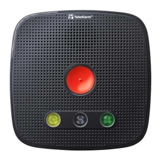
Page 12: Product Description
If you require help, press the Emergency call button to initiate a call. The call will be answered either by a person at the alarm receiving centre, a relative or other individual, according to the programmed destination. © TeleAlarm SA TA74_UM_EN_V2.5_2019.09_Final... -
Page 13: Action Button ("S" Button)
Service Call and you will hear the announcement <Service Call>. 4.3.4 Action button: device status If there is a malfunction, the Action button flashes. Press the Action button to hear an announcement of the detected problem. TA74_UM_EN_V2.5_2019.09_Final © TeleAlarm SA... -
Page 14: Daily Button
Pressing the Sign in / sign out button tells the device whether you are currently at home or not. 4.5.1 Sign out When you leave home, press the Sign in / sign out button. You will hear the announcement <Sign out>. The activity monitor is temporarily disabled. © TeleAlarm SA TA74_UM_EN_V2.5_2019.09_Final... -
Page 15: Sign In
See section 4.6.3 Standby, normal mode The device is in standby. Standby, battery-operated Standby mode with the Action button set as service button Pre-alarm Can be cancelled with the Action button Connection Connection established TA74_UM_EN_V2.5_2019.09_Final © TeleAlarm SA... - Page 16 Daily button every day. Signed in, battery operation Active time frame, normal mode Press the Daily button now Active time frame, battery operation Pre-alarm activity monitor Cancel with the Daily button Sign in by staff © TeleAlarm SA TA74_UM_EN_V2.5_2019.09_Final...
-
Page 17: Local Voice Announcements From The Device
When the Daily button is pressed before the end of the time frame <Activity monitor expired> When an activity monitor alarm is sent <Alarm input> When the external input is activated (TA74 IO and TA74 GSM IO only) TA74_UM_EN_V2.5_2019.09_Final © TeleAlarm SA... -
Page 18: Error Messages
<Failure two [x]> Phone 3 beeps Wireless transmitter [x] battery empty. Replace the wireless transmitter battery. <Failure three [x]> Phone 4 beeps Wireless transmitter [x] radio transmission failure. Check the wireless transmitter. © TeleAlarm SA TA74_UM_EN_V2.5_2019.09_Final... -
Page 19: Installation
To optimise battery lifetime, place the TA74 GSM or TA74 GSM IO in a location where the GSM signal level is as good as possible. In the case of a very weak GSM signal, the battery lifetime could be reduced. TA74_UM_EN_V2.5_2019.09_Final © TeleAlarm SA... - Page 20 The changeover to digital IP telecommunication is inevitable and already in progress. For this reason, TeleAlarm urgently recommends the use of digital protocols such as RBIP or SCAIP in order to ensure reliable alarm transmission.
-
Page 21: Installing The Ta74
3. Adjust the screw depth. INFO If the device is mounted on the wall, the cables can be fed through the cable channels and through the opening on the front of the unit. < 5 mm 152 mm TA74_UM_EN_V2.5_2019.09_Final © TeleAlarm SA... -
Page 22: Connecting The Ta74
2. Fit the plug of the telephone cable into the socket of the telephone outlet. NOTE Only connect the device to a telephone outlet that has been correctly installed by your telephone service provider. The TA74 is designed to be connected to the public telephone network. © TeleAlarm SA TA74_UM_EN_V2.5_2019.09_Final... -
Page 23: External Phone Connection
Risk to the person in need of assistance as a result of failed emergency calls. With a private branch exchange (PABX or a digital box), there is no guarantee that a phone call will be interrupted by the emergency call. TA74_UM_EN_V2.5_2019.09_Final © TeleAlarm SA... -
Page 24: Ethernet (Lan) Connection
Prioritising an emergency call may not always be possible. NOTE The TA74 should only be connected to a device with the autonegotiation procedure enabled for Ethernet communication. NOTE Use only the original flat LAN cable supplied by TeleAlarm. © TeleAlarm SA TA74_UM_EN_V2.5_2019.09_Final... -
Page 25: Gsm (Cellular Network) Connection
The quality of the communication depends on the chosen protocol, the GSM signal level and the service provider. NOTE Be aware of potential limitations due to network availability. Prioritising an emergency call may not always be possible. TA74_UM_EN_V2.5_2019.09_Final © TeleAlarm SA... - Page 26 Check the duration and conditions of the SIM card contract. Make sure the SIM card contract has no restrictions with regard to data connection, voice connection, credit or connection time. Do not use pre-paid contracts for these devices. INFO The TA74+ can be upgraded by adding an internal GSM module. © TeleAlarm SA TA74_UM_EN_V2.5_2019.09_Final...
-
Page 27: External Gsm Antenna Connection
The TA74+ is equipped with an internal GSM antenna. If required, an external antenna can be connected. NOTE Connect only an original TeleAlarm antenna, as otherwise, the functionality is not ensured. 1. Remove the power plug from the socket (6); see figure in section 5.3.7 "Power connection". NOTE The internal date and time are erased and must be set again after reconnection. -
Page 28: Internal Input/Output
However, it is possible to connect an external telephone to the PSTN connector together with the phone line, using a special splitter. The splitter can be ordered from TeleAlarm. 1. Remove the power plug from the socket (6); see figure in section 5.3.7 "Power connection". - Page 29 The device is equipped with one isolated, normally open relay contact (1 A, 30 V DC, 0.3 A, 30 V RMS) and one potential-free input. The external input is pulled by a resistor (Pin 1). A switch or an external relay can be used to connect the input signal to ground (Pin 6). TA74_UM_EN_V2.5_2019.09_Final © TeleAlarm SA...
-
Page 30: Power Connection
6 months to allow the battery to charge. 5.3.8 Performing a test Once the device is installed and programmed, perform a test immediately by triggering an alarm with the wireless transmitter. See also section 8.6 "Test instructions". © TeleAlarm SA TA74_UM_EN_V2.5_2019.09_Final... -
Page 31: Switching Off
The internal date and time are erased and must be set again after reconnection. INFO If you remove the power adapter from your power outlet, the unit announces 'power failure'. The device will then automatically switch to battery operation. TA74_UM_EN_V2.5_2019.09_Final © TeleAlarm SA... -
Page 32: Programming
Daily button is pressed or the preset time has elapsed. If the reminder message is not acknowledged, the device can send an alert to the alarm receiving centre. Please refer to the Reference Manual and the Configuration Manager Manual for more information on programming. © TeleAlarm SA TA74_UM_EN_V2.5_2019.09_Final... -
Page 33: Special Button Functions
1. Press the Maintenance button for at least 20 seconds. 2. The device announces <Setup reset>. The device is now non-operational; it has to be reprogrammed via the Configuration ® Manager or the platform TeleAlarm Cloud Services. Please refer to the Reference Manual for more information on programming. NOTE This function deletes all user settings and restores the default settings. -
Page 34: Entering Service Mode
Function 5 GSM signal level test. See Section 6.7, Page 38. Function 6 Call progress tones audible. See Section 6.8, Page 39. INFO To use function 4, the wireless transmitter must already be registered in the TA74. © TeleAlarm SA TA74_UM_EN_V2.5_2019.09_Final... -
Page 35: Exiting Service Mode
3. Press the wireless transmitter button to register the device with the TA74. 4. Press the wireless transmitter button a second time to confirm the pairing between the two devices. ► After having performed the pairing, the TA74 automatically exits Service mode. TA74_UM_EN_V2.5_2019.09_Final © TeleAlarm SA... -
Page 36: Setting Dynamic Host Configuration Protocol (Dhcp) And Announcing Ip Address
► After changing the DHCP mode, the TA74 exits Service mode automatically. INFO If the DHCP is disabled, the device will have a static IP address. For more information, see the Reference Manual. The default address is 192.168.1.10. © TeleAlarm SA TA74_UM_EN_V2.5_2019.09_Final... -
Page 37: Wireless Transmitter Range Test
3. Press any button on the TA74 to exit the test mode. INFO Every time the TA74 receives a signal from a registered wireless transmitter, the 3-minute timer will be reset. If no signal is received during 3 minutes, the TA74 will automatically return to standby mode. TA74_UM_EN_V2.5_2019.09_Final © TeleAlarm SA... -
Page 38: Gsm Signal Level Test
GSM signal level test mode at the end of the 3 minutes. ► The red indicator lamp flashes every 2 seconds and the device announces the GSM signal level every 3 seconds. 2. Press any button on the TA74 to exit the test mode. © TeleAlarm SA TA74_UM_EN_V2.5_2019.09_Final... -
Page 39: Call Progress Tones Audible
2. Press the Emergency call button to change the status of the "call progress tones" parameter. ► After performing the change, the TA74 announces the new status (<0> = disabled, <1> = enabled) and exits Service mode automatically. TA74_UM_EN_V2.5_2019.09_Final © TeleAlarm SA... -
Page 40: Additional Devices
Test the range of the wireless transmitter within your entire home area. Within buildings, a maximum range of 30 to 50 meters is achieved, or up to 300 meters in the open air. © TeleAlarm SA TA74_UM_EN_V2.5_2019.09_Final... -
Page 41: Installing Wireless Transmitter On Necklace
1. Insert the thin wire in the hole of the ring. 2. Pass the necklace cord through the loop formed by the thin wire. 3. Pull the necklace cord until the thin wire is passed around the ring. TA74_UM_EN_V2.5_2019.09_Final © TeleAlarm SA... -
Page 42: Shortening The Necklace Cord
Do not tie knots in the cord. Wireless detectors Up to 20 wireless transmitters can be registered to your TA74. In order to work correctly, they must be paired to your device. For more information, see the Reference Manual. © TeleAlarm SA TA74_UM_EN_V2.5_2019.09_Final... -
Page 43: Operation
The TA74 will automatically dial the next call number. INFO Instead of the subscriber number, a personal message can be recorded, e.g. <This is Mrs. Brown's emergency call unit...>. For more information, see the Reference Manual. TA74_UM_EN_V2.5_2019.09_Final © TeleAlarm SA... -
Page 44: Emergency Call To A Voip Phone
Reject the call and terminate. The TA74 dials the next number on the list. Activate the relay output for 10 seconds (TA74 IO and TA74 GSM IO only) INFO: The parameter Activate output must be set to "Remote activation." © TeleAlarm SA TA74_UM_EN_V2.5_2019.09_Final... -
Page 45: Taking Phone Calls
Taking phone calls with the wireless transmitter 1. To answer a phone call with the wireless transmitter, press the button of your wireless transmitter when the phone rings. 2. To terminate the call, press the button of your wireless transmitter again. TA74_UM_EN_V2.5_2019.09_Final © TeleAlarm SA... -
Page 46: Test Instructions
In the factory setting, the following components are monitored: Radio transmission monitoring Radio transmission between the TA74 and all programmed wireless components is tested every 21 hours. If alarm receivers are configured, the error message and the re-establishment of radio transmission are transmitted automatically. © TeleAlarm SA TA74_UM_EN_V2.5_2019.09_Final... - Page 47 If alarm receivers are configured, the error message and re-establishment of the line are transmitted automatically. In the case of PSTN and Ethernet, this takes place after one minute, in the case of GSM after 60 minutes. TA74_UM_EN_V2.5_2019.09_Final © TeleAlarm SA...
-
Page 48: Cleaning, Disinfection, Maintenance, Reuse
Clean the TA74 and the wireless transmitter with a soft, dry cloth or soft brush. Remove stubborn dirt with a damp but not wet cloth and a pH-neutral cleaning agent. To disinfect the TA74 and the wireless transmitter by wiping, TeleAlarm recommends an alcohol-free disinfectant with proven effectiveness (as listed by the Association for ®... -
Page 49: Maintenance
1. Replace the unit battery of the TA74 after five years at the latest, see section 9.5 "Replacing the unit battery". TeleAlarm recommends replacing the battery with a replacement battery from TeleAlarm after only three years (order number T.200.001.296). -
Page 50: Disposing Of The Device
Waste Electrical and Electronic Equipment). To dispose of old electrical or electronic devices, you should use the return and collection systems established in the country concerned. Old unit batteries should be disposed of in the same manner. © TeleAlarm SA TA74_UM_EN_V2.5_2019.09_Final... -
Page 51: Replacing The Unit Battery
NOTE The TA74 should be serviced by trained and authorised personnel only. NOTE Use only original batteries made for the corresponding device and supplied by TeleAlarm. Any other batteries could damage the device. To replace the battery: 1. Disconnect all plugs from the device. Begin with the power supply. - Page 52 2. Unscrew the four screws on the bottom of the device and remove the lower cover. 3. Disconnect the plug of the unit battery from the device. 4. Lever off the battery with a screwdriver and release it from the two braces. Pull it out gently. © TeleAlarm SA TA74_UM_EN_V2.5_2019.09_Final...
- Page 53 9. Connect all plugs to the device as described in section 5.3 "Connecting the TA74". 10. Perform a test as described in section 8.6 "Test instructions". 11. Dispose of the old battery as described in section 9.4 "Disposing of the device". TA74_UM_EN_V2.5_2019.09_Final © TeleAlarm SA...
-
Page 54: Replacing The Battery Of The Wireless Transmitter
If the battery compartment does not close securely, stop using the product and keep it out of the reach of children. If a battery has been swallowed or is inside any part of the body, seek immediate medical attention. © TeleAlarm SA TA74_UM_EN_V2.5_2019.09_Final... -
Page 55: Appendix
User guidance Synthetic speech and LED indication User assistant "Synthetic speech disabled" mode Programming options – LAN using the Configuration Manager – Remote programming via TeleAlarm Cloud Services ® – Remote programming from an alarm receiving centre – Service mode TA74_UM_EN_V2.5_2019.09_Final... - Page 56 3 means protection against solid foreign objects with a diameter of ≥ 2.5 mm and against access with a tool. The second digit has the following meaning: 2 means protection against dripping water if the housing is inclined up to 15°. 0 means no protection against water. © TeleAlarm SA TA74_UM_EN_V2.5_2019.09_Final...
-
Page 57: Technical Specifications Of Wireless Transmitter
*) The first digit of the degree of protection IP67 has the following meaning: 6 means dust-tight. The second digit has the following meaning: 7 means protection against submersion for up to 30 minutes at a maximum depth of 1 metre. TA74_UM_EN_V2.5_2019.09_Final © TeleAlarm SA... -
Page 58: Certifications And Approvals
EN 301 511 V12.5.1 (for GSM module only) – EN 301 908-2 V11.1.1 (for GSM module only) – EN 301 489-7 V1.3.1 (for GSM module only) – EN 301 489-24 V1.5.1 (for GSM module only) – EN 300220-2 V3.1.1 (Category 1 radio receiver) © TeleAlarm SA TA74_UM_EN_V2.5_2019.09_Final... -
Page 59: Licences
GSM network. The wireless transmitter that is supplied with the device uses the frequency specially reserved for emergency calls in Europe. We, TeleAlarm , declare that the above-mentioned products are manufactured in ® compliance with EU Directives LVD 2014/35/EU, EMC 2014/30/EU, RED 2014/53/EU and RoHS 2011/65/EU. TA74_UM_EN_V2.5_2019.09_Final © TeleAlarm SA... - Page 60 TeleAlarm SA Rue du Pont 23 2300 La Chaux-de-Fonds Switzerland www.telealarm.com © Copyright TeleAlarm SA, 2019 TeleAlarm Europe GmbH Hertzstraße 2 04329 Leipzig Germany Contact in UK Tel: +44 (0) 333 0124392 info-uk@telealarm.com...
Need help?
Do you have a question about the TA74+ and is the answer not in the manual?
Questions and answers