
Related Manuals for TeleAlarm TA74


Summary of Contents for TeleAlarm TA74
- Page 1 User Manual TA74 TA74+, TA74 GSM, TA74 GSM IO TA74_UM_EN_V2.2_2018.03 User Manual...
- Page 2 THIS PAGE IS LEFT INTENTIONALLY BLANK...
-
Page 3: Table Of Contents
TA74 User Manual | en Table of contents Safety ................6 Intended use ................... 6 Improper use .................. 6 User qualification ................7 Used warnings and symbols ............7 Safety instructions ................7 Features ................9 Product comparison ..............10 Scope of delivery ............ - Page 4 6.3.1 Maintenance button ..................33 6.3.2 Reset the TA74 ....................33 6.3.3 Restore the TA74 to default settings .............. 33 6.3.4 Enter Service mode ..................34 6.3.5 Exit Service mode ................... 35 Wireless transmitters 1 and 2 registration ........35 DHCP setting and IP address announcement ......
- Page 5 TA74 User Manual | en Operation ............... 42 Emergency call to an alarm receiving centre ....... 42 Emergency call to a landline telephone ........42 Emergency call to a SIP phone ............ 43 Key functions on a landline telephone or a SIP phone ....43 Taking phone calls ...............
-
Page 6: Safety
Intended use Intended use means that the TA74 may only be operated within the limits of its technical specifications and in conformity with the information given in these instructions. Any other use will be regarded as misuse and can result in malfunctions and damage. -
Page 7: User Qualification
When unplugging the unit from the power outlet, never pull on the power cord but always grip the power adapter. – Connect the TA74 only to a professionally installed 100 - 240 V AC, 50/60 Hz power outlet with an up to 16 A fuse. –... - Page 8 Comply with your national regulations, guidelines and requirements for the disposal of end-of-life electrical equipment and batteries. – Be sure to allow the required space around the device. The TA74 must be easily accessible. – The wireless transmitter provided with the TA74 contains a button cell battery. If the button cell battery is swallowed, it can cause severe internal burns in just 2 hours and can lead to death.
-
Page 9: Features
The device has two basic operating modes: 1. The TA74 is part of a social alarm system that consists of an alarm receiving centre that can be reached at any time and the device itself. Calls are sent to this alarm receiving centre. -
Page 10: Product Comparison
| Features TA74 User Manual NOTICE This unit shall be tested weekly. See section 8.6 Test instructions. Product comparison TA74 TA74+ TA74 GSM TA74 GSM IO Multi-protocol Recordable voice message PSTN connection ... -
Page 11: Scope Of Delivery
TA74 User Manual Scope of delivery | en Scope of delivery 1. TA74 including pre-installed rechargeable backup battery 2. Quick guide 3. Power adapter 4. Phone cable with country-specific telephone plug and optional network cable 5. Necklace or bracelet 6. Wireless transmitter (battery included) WARNING! To reduce risk of fire and electric shock, replace only with identical components and parts. -
Page 12: Product Description
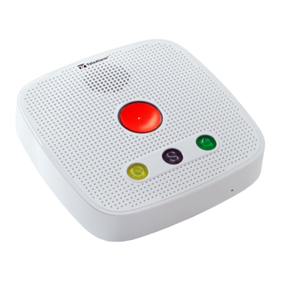
| Product description TA74 User Manual Product description Unit description 1. Daily button 2. Action button 3. Sign in / sign out button 4. Emergency call button 5. Maintenance button Emergency call button If you require help, press the Emergency call button to initiate a call. -
Page 13: Action Button ("S" Button)
4.3.2 Take the first incoming call If your TA74 is delivered to you unprogrammed, this special function allows you to accept the first incoming call (PSTN connection only). ► Press the Action button 3 times within 3 seconds. -
Page 14: Daily Button
TA74 User Manual Daily button The TA74 has a built-in activity monitor, which ensures that an emergency call is made automatically if the Daily button is not pressed within a preset period of time. The light on the Daily button lights up when it should be pressed. -
Page 15: Sign In
This signs you in. Device indications 4.6.1 Light signals The TA74 has four indicator lamps that display the status of the unit. The symbols have the following meanings: Lamp shines bright Lamp shines dull Lamp blinks (0.5 s) Lamp blinks twice (0.5 s) - Page 16 | Product description TA74 User Manual Status Description or action Blue Speak Speak (indication for the hearing impaired) Listen Listen (indication for the hearing impaired) Repeated call When a call is repeated Call activated If the call is not acknowledged, a new...
-
Page 17: Local Voice Announcements From The Unit
<Activity monitor reset> When the Daily button is pressed before the end of the time frame <Activity monitor alarm> When an activity monitor alarm is sent <Alarm input> When the external input is activated (TA74 GSM IO only) TA74_UM_EN_V2.2_2018.03_Final © TeleAlarm SA... -
Page 18: Error Messages
| Product description TA74 User Manual 4.6.3 Error messages Error messages are announced by the TA74 locally and/or by the telephone in phone protocols. When the TA74 is in synthetic speech disabled mode, error messages are only announced by beeps. Voice... -
Page 19: Installation
The power adapter of the TA74 must placed at least 10 cm away from the device. – The power adapter must be plugged into a wall socket in the proximity of the TA74 and must remain easily accessible at all times. - Page 20 The alarm might successfully pass sometimes, but it cannot be guaranteed. A shift to digital IP telecommunication is inevitable and already underway. This is why TeleAlarm strongly recommend the use of digital protocols like RBIP or SCAIP to ensure reliable alarm transmission.
-
Page 21: Placing The Ta74
5.2.1 Placing on a surface The TA74 is designed for use at home. Many items of furniture are coated with a variety of paints, varnishes and plastics. The feet of the TA74 may leave marks on furniture as a result of chemical processes. -
Page 22: Connecting The Ta74
5.3.1 PSTN connection 1. Insert the plug of the telephone cable into the socket (1) on the TA74. Feed the cord through the cable channel and through the opening on the back of the unit. 2. Fit the plug of the telephone cable into the socket of the telephone outlet. -
Page 23: External Telephone Connection
External telephone connection (all models except TA74 GSM IO) 1. Insert the plug of the external telephone cable into the socket (2) on the TA74. Feed the cord through the cable channel and through the opening on the back of the unit. -
Page 24: Ethernet (Lan) Connection
5.3.3 Ethernet (LAN) connection 1. Insert the plug of the network connection cable into the socket (3) on the TA74. Feed the cord through the cable channel and through the opening on the back of the unit. 2. According to your installation, fit the other end of the network connection cable into your router outlet or switch. -
Page 25: Gsm (Cellular Network) Connection
5.3.4 GSM (cellular network) connection (TA74+ if a GSM module is installed,TA74 GSM and TA74 GSM IO only) 1. Remove the cover over the SIM socket (4). 2. Open the metal clamp of the SIM card slot by sliding it to the left, and then lift the clamp 3. - Page 26 | Installation TA74 User Manual INFO The TA74+ is upgradeable by adding an internal GSM module. © TeleAlarm SA TA74_UM_EN_V2.2_2018.03_Final...
-
Page 27: External Gsm Antenna Connection
NOTICE Place the antenna at minimum 1 meter from the TA74. The antenna can be fixed with the magnetic holder, with screws or with the integrated adhesive tape 3. Reconnect the TA74 to the power supply. -
Page 28: I/O Connection
2. Connect the external equipment to the I/O cable. 3. Insert the plug of the I/O cable into the socket (2) on the TA74. Feed the cord through the cable channel and through the opening on the back of the unit. - Page 29 Pin 6 External input GND The TA74 GSM IO provides one isolated, normally open relay contact (1 A, 30 V DC, 0.3 A, 30 V RMS) and one potential-free input. The external input is pulled by a resistor (Pin 1).
-
Page 30: Power Connection
5.3.7 Power connection 1. Insert the plug of the power adapter into the socket (6) on the TA74. Feed the cord through the cable channel and through the opening on the back of the unit. 2. Plug the power adapter into the power outlet. -
Page 31: Switch Off
TA74 User Manual Installation | en Switch off To switch the TA74 off without battery operation, remove the power plug from the socket (6). NOTICE The internal date and time are erased and must be set again after reconnection. INFO If you remove the power adapter from your power outlet, the unit announces 'power failure'. -
Page 32: Programming
| Programming TA74 User Manual Programming Before you program the TA74 you must be familiar with all of the unit's functions. Programming is specifically intended for trained and authorized personnel only. NOTICE Correct programming of the TA74 is highly important for the full function of the unit. -
Page 33: Special Key Functions
1. Press the Maintenance button for 0.5 to 2 seconds and then release it. 2. The unit beeps and reboots. 6.3.3 Restore the TA74 to default settings 1. Press the Maintenance button for at least 20 seconds. 2. The unit announces <Setup reset>. -
Page 34: Enter Service Mode
Feature 5 GSM signal level test, see section 6.7, page 38 Feature 6 Call progress tones audible, see section 6.8, page 38 INFO To use feature 4, the wireless transmitter must already be registered into the TA74. © TeleAlarm SA TA74_UM_EN_V2.2_2018.03_Final... -
Page 35: Exit Service Mode
1. Press the Maintenance button and use feature 1 or 2. ► If needed, see section 6.3.4 Enter Service mode, page 34. ► It is possible to assign up to two wireless transmitters to the TA74 (the first with feature 1 and the second with feature 2). -
Page 36: Dhcp Setting And Ip Address Announcement
► The TA74 will automatically announce the DHCP status and its IP address. 2. Press the Emergency call button to switch on/off the DHCP. ► After performing the change of the DHCP mode, the TA74 exits Service mode automatically. INFO If the DHCP is disabled, the device will have a static IP address. -
Page 37: Wireless Transmitter Range Test
Programming | en Wireless transmitter range test It is possible to set the TA74 into test mode in order to test the radio range of the wireless transmitter. By pressing the wireless transmitter button the TA74 plays an acoustic signal without starting an alarm. -
Page 38: Gsm Signal Level Test
2. Press the Emergency call button to change the status of the "call progress tones" parameter. ► After performing the change, the TA74 announces the new status (<0> = disabled, <1> = enabled) and exits Service mode automatically. © TeleAlarm SA... -
Page 39: Additional Devices
1. Press the button on the wireless transmitter. ► The indicator lamp lights up once as confirmation. ► The TA74 announces <Radio button x> (x is the number of the wireless transmitter) and the call sequence starts. An emergency call made by mistake can be cancelled during the pre-alarm by pressing the Action button on the TA74. -
Page 40: Necklace Installation
| Additional devices TA74 User Manual Necklace installation 1. Insert the thin wire in the hole of the ring. 2. Pass the necklace cord in the loop formed by the thin wire. 3. Pull the necklace cord until the thin wire is passed around the ring. -
Page 41: Shortening The Necklace's Cord
NOTICE Do not tie knots in the cord. Wireless detectors Up to 20 wireless transmitters can be registered to your TA74. They must be paired to your device to work correctly. For more information, refer to the Reference Manual. TA74_UM_EN_V2.2_2018.03_Final... -
Page 42: Operation
The communication is then established in full duplex. INFO If key 7 is not pressed on the phone, the TA74 hangs up after playing its message, then continues the call sequence. 6. Once the call has been accepted, the following features are available (see table in section 8.4 Key functions on a landline telephone or a SIP phone, page 43. -
Page 43: Emergency Call To A Sip Phone
Operation | en Emergency call to a SIP phone The TA74 can be programmed to send an emergency call to a SIP phone. The emergency call from the TA74 is received like explained in section 8.2 Emergency call to a landline telephone, except for the following differences: –... -
Page 44: Taking Phone Calls
Incoming call recognition must not be set to "OFF". Refer to the Reference Manual. Taking phone calls with the TA74 1. To answer a phone call with the TA74, press the Emergency call button when the phone rings. 2. To terminate the call, press the Emergency call button again. -
Page 45: Test Instructions
Make sure you perform a test regularly, by sending a manual test alarm with the wireless transmitter. This will test the wireless connection between the wireless transmitter and the TA74. It will also test the connection of the TA74 to the alarm receiving centre. WARNING! Risk to the person in need of assistance from failed emergency calls. -
Page 46: Maintenance
® – If a liquid is spilled into the loudspeaker holes or the buttons of the TA74, simply hold the unit upside down to remove the liquid from the unit. Gently shake if necessary. Perform a test to check proper speech function (see section 8.6 Test instructions). -
Page 47: Replacing The Backup Battery
Maintenance | en Replacing the backup battery The backup battery of the TA74 has a limited lifetime and should be replaced after three years, or if the device announces the error <Unit battery empty>. Replace the battery even if the TA74 is powered all the time by the main power. - Page 48 | Maintenance TA74 User Manual 2. Unscrew the four screws on the bottom of the device and remove the back cover. 3. Disconnect the plug of the backup battery from the device. 4. Lever off the battery with a screwdriver and release it from the two braces. Pull it out gently from its location.
- Page 49 8. Place the cover back on the device and screw in the four screws. 9. Reconnect all the plugs to the unit, as explained in section 5.3 Connecting the TA74. 10. Perform a test as explained in section 8.6 Test instructions.
-
Page 50: Replacing The Wireless Transmitter Battery
| Maintenance TA74 User Manual Replacing the wireless transmitter battery The battery of the wireless transmitter should be replaced when the integrated LED flashes three times when the button is pressed. NOTICE The wireless transmitter should be serviced by trained and authorized personnel only. -
Page 51: Appendix
3.6 V NiMH battery, 2.2 Ah Battery operating time TA74, TA74+: min. 48 h with one 30 min. call. TA74 GSM, TA74 GSM IO: min. 36 h with one 30 min. call. All values at date of purchase with a fully charged battery Current consumption –... -
Page 52: Certifications And Approvals
Phone line (PSTN) – External telephone – LAN/Ethernet (10/100 MB/s) connection – micro-SIM card socket (TA74+, TA74 GSM, TA74 GSM IO) – Internal I/O (TA74 GSM IO only) Vocal reminders – 3 recordable (15 sec.) reminder messages (timing day/hour) 10.2... -
Page 53: Licences
10.3 Licences The TA74 firmware contains a library, called lwIP, which is licensed under the BSD licence: Copyright © 2001-2004 Swedish Institute of Computer Science. All rights reserved. The lwIP library redistribution and use in source and binary forms, with or without modification, are permitted provided that the following conditions are met: 1. - Page 54 | Appendix TA74 User Manual THIS PAGE IS LEFT INTENTIONALLY BLANK © TeleAlarm SA TA74_UM_EN_V2.2_2018.03_Final...
- Page 55 TA74 User Manual Appendix | en THIS PAGE IS LEFT INTENTIONALLY BLANK TA74_UM_EN_V2.2_2018.03_Final © TeleAlarm SA...
- Page 56 TeleAlarm SA Rue du Pont 23 2300 La Chaux-de-Fonds Switzerland www.telealarm.com © Copyright TeleAlarm SA, 2018 TeleAlarm Europe GmbH Hertzstraße 2 04329 Leipzig Germany Contact in UK Tel: +44 (0) 333 0124392 info-uk@telealarm.com...
Need help?
Do you have a question about the TA74 and is the answer not in the manual?
Questions and answers
I **** attending a hosp appointment & wish to deactivate my Tele Alarm TA74 from 10am-1pm today. How do I do this ?
I wish 2 deactivate. My Tele Alarm system from 10am-1pm today, how do I do this