
Related Manuals for Tecnosystemi ProAIR Multi-Zone Series


Summary of Contents for Tecnosystemi ProAIR Multi-Zone Series
-
Page 1: User Manual
COD. CMU00050 Rev.01 / Luglio 2019 USER MANUAL TO BE KEPT proAIR multi-zone proAIR pack SERIAL NUMBER... -
Page 2: Table Of Contents
1. WALL-MOUNTED CHRONO-THERMOSTAT WITH BATTERIES IN RADIO FREQUENCY “DISCOVERY 2X” Page BASIC USE OF THE CHRONO-THERMOSTAT FOR THE USER Page BASIC CONFIGURATION (addressed to the user) Page 1) LOCKING / UNLOCKING THE CHRONO-THERMOSTAT Page 2) SWITCHING ON / SWITCHING OFF THE SYSTEM (ONLY BY THE MASTER CHRONO-THERMOSTAT) Page 3) SWITCHING ON / SWITCHING OFF OF THE ZONE CHRONO-THERMOSTAT Page... - Page 3 A) STATUS OF THE THERMOSTATS Page 43 B) STATUS OF THE ACTUATORS (motors) Page 43 C) ASSOCIATION / ZONE NAME Page 44 D) CONFIGURATION Page 44 1) PERCENTAGES OF OPENINGS Page 45 2) SET-POINT DIFFERENCE Page 45 3) OPERATING PARAMETERS Page 46 3.1) MINIMUM / MAXIMUM SETPOINT Page 46...
-
Page 4: Basic Use Of The Chrono-Thermostat For The User
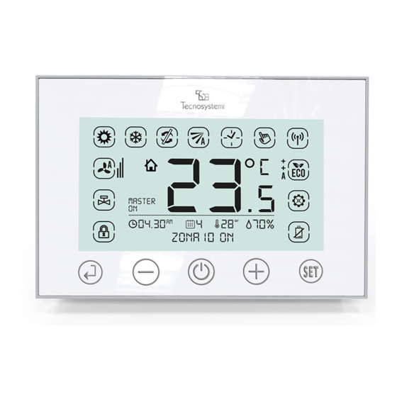
proAIR CHRONO-THERMOSTAT INSTRUCTIONS DISCOVERY 2X multi-zone 1. WALL-MOUNTED CHROMO-THERMOSTAT WITH BATTERIES IN RADIO FREQUENCY TOUCH SCREEN "DISCOVERY 2X" 1.1 BASIC USE OF THE CHRONO-THERMOSTAT FOR THE USER The chrono-thermostat Discovery 2X, allows the adjustment of a different Set-point temperature from zone to zone, the adjustment of the air flow and the setting in the Thermostat or Chrono-thermostat function, therefore allowing it to meet the needs of setting in autonomy at any time. - Page 5 proAIR CHRONO-THERMOSTAT INSTRUCTIONS DISCOVERY 2X multi-zone VIEWING SETTINGS ICONS THERMOSTAT IN MANUAL MODE. Sets the temperature only in the manual mode. CHRONO-THERMOSTAT (TIMER). Programmes the time ranges and the temperature. DAMPER MOVEMENT. Sets the opening position of the damper or motorised grille. COOLING (SUMMER).
-
Page 6: Basic Configuration (Addressed To The User)
proAIR CHRONO-THERMOSTAT INSTRUCTIONS DISCOVERY 2X multi-zone 1.2 BASIC CONFIGURATION (addressed to the user) PLEASE NOTE: The communication system between thermostats and control unit takes place with a signal in Radio frequency: any setting carried out on the chrono-thermostats is sent and managed by the control unit in real time. Automatic updating of the data between the chrono-thermostats and control unit takes place in a maximum time of 5 min. - Page 7 proAIR CHRONO-THERMOSTAT INSTRUCTIONS DISCOVERY 2X multi-zone 2.2 Before "MASTER OFF" stops blinking (max 8 seconds), press the key again. When the settings "MASTER OFF" and "ZONE 1 OFF" no longer flash, all the dampers or motorised grilles close and the ducted units will switch off.
-
Page 8: Summer / Winter Setting Of The Proair System (Only By The Master Chrono-Thermostat)
proAIR CHRONO-THERMOSTAT INSTRUCTIONS DISCOVERY 2X multi-zone 4.2 Press the key to change the temperature value: to confirm press the key or wait for the sound of automatic confirmation after 3 seconds. 5. SUMMER - WINTER SETTING OF THE PROAIR SYSTEM (ONLY BY THE MASTER CHRONO-THERMOSTAT) To set the summer / winter mode of the Proair system, it is necessary to access the parameters of the MASTER chrono-thermostat. - Page 9 proAIR CHRONO-THERMOSTAT INSTRUCTIONS DISCOVERY 2X multi-zone b. The settable SetPoint for the ducted unit varies from min 18°C to max 30°C (always refer to the user manual of the remote control). Dehumidification (Summer + “dE“). With the master chrono unlocked, enter the setting mode and using the key select the symbol (flashing) + “dE”...
-
Page 10: Advanced Configurations (For Qualified Personnel And Technical Assistance Centre)
proAIR CHRONO-THERMOSTAT INSTRUCTIONS DISCOVERY 2X multi-zone 7. ERROR REPORTING (appearing in the display) MASTER MASTER MASTER Fig.13 Fig.14 Fig.15 : Accompanied by the flashing symbol, indicates the lack of RF (Radio frequency) communication with the Control unit of the system. Check that the control unit is installed nearby (max. - Page 11 proAIR CHRONO-THERMOSTAT INSTRUCTIONS DISCOVERY 2X multi-zone TIME RANGE 1 Fig.17 Fig.18 Fig.19 08.30 04.30 Fig.20 Fig.21 Fig.22 1.1 Unlock by pressing for 3 seconds, press for 3 seconds, press repeatedly until the flashing of the symbol . Press once to confirm. (Fig.17) 1.2 Press the key, check the flashing day of the week: press to select the day to...
- Page 12 proAIR CHRONO-THERMOSTAT INSTRUCTIONS DISCOVERY 2X multi-zone TIME RANGE 3 20.00 13.00 20.00 17 00 17.00 Fig.27 Fig.28 Fig.29 Fig.30 3.1 Check the flashing of OFF and range F3, press the key to set ON and confirm with . (Fig.27) 3.2 Set the switch-on time ON of the F3 range (17:00) and confirm with .
- Page 13 proAIR CHRONO-THERMOSTAT INSTRUCTIONS DISCOVERY 2X multi-zone 2. MANAGEMENT AND CONFIGURATION OF THE ADJUSTMENT OF THE DAMPER / GRILLE This function, applicable from each zone chrono-thermostat, allows you to set the mode of movement of the damper or motorised grille installed, in the room where the chrono-thermostat is located, according to two different functions: A) PROPORTIONAL / AUTOMATIC SETTING The opening and closing movement of the damper or grille will be automatic from position to position, based on the set temperature (E.g.: If 20 °C is set and in the room it is 30 °C, all the vanes will open up to 100%...
- Page 14 proAIR CHRONO-THERMOSTAT INSTRUCTIONS DISCOVERY 2X multi-zone : Press to set the opening to position A2 (66%), the icon appears, press to confirm and exit the setting mode. (Fig.39) Press to set the opening to position A3 (100%), the icon appears, press to confirm and exit the setting mode.
- Page 15 proAIR CHRONO-THERMOSTAT INSTRUCTIONS DISCOVERY 2X multi-zone PLEASE NOTE: • In the absence of a power supply, the chrono-thermostat DOES NOT LOSE ITS SETTINGS. • When replacing the batteries, the chrono-thermostat DOES NOT LOSE ITS SETTINGS. • During the change of the hour (time zone) remember to reset the time from the MASTER thermostat (all the other Chrono-thermostats will be automatically updated, time max.
-
Page 16: Resetting The Chrono-Thermostat
THIS OPERATION IS VERY DELICATE AND MUST BE PERFORMED BY SKILLED PERSONNEL (INSTALLER OF THE SYSTEM / TECNOSYSTEMI SERVICE CENTRE) BECAUSE IF THE RESETTING OF THE CHRONO- THERMOSTAT IS NOT BE EXECUTED CORRECTLY IT CAN AFFECT THE OPERATION OF THE PROAIR SYSTEM. -
Page 17: Dimensions And Components Of The Chrono-Thermostat Discovery 2X
proAIR CHRONO-THERMOSTAT INSTRUCTIONS DISCOVERY 2X multi-zone 1.5 DIMENSIONS AND COMPONENTS OF THE CHRONO-THERMOSTAT DISCOVERY 2X 138 mm TECHNICAL SPECIFICATIONS • POWER SUPPLY: WITH 2 x 1.5 V AA (LR6) BATTERIES INCLUDED • DATA TRANSMISSION: IN RF AT 868 MHz • RF SIGNAL RANGE 50 m MAX IN OPEN FIELD BETWEEN CHRONO- THERMOSTAT AND POLARIS 2X CONTROL UNIT... -
Page 18: Wall-Mounted Chrono-Thermostat With Batteries In Radio Frequency "Mini - Discovery 2X
proAIR CHRONO-THERMOSTAT INSTRUCTIONS MINI DISCOVERY 2X multi-zone WALL-MOUNTED CHRONO-THERMOSTAT WITH BATTERIES IN RADIO FREQUENCY TOUCH “MINI DISCOVERY 2X” 2.1 BASIC USE OF THE CHRONO-THERMOSTAT FOR THE USER The MiniDiscovery 2X is a chrono-thermostat with “zone” functions (Slave, without possibility to become Master) powered by batteries for Proair multi-zone systems. -
Page 19: Basic Configuration (Addressed To The User)
proAIR CHRONO-THERMOSTAT INSTRUCTIONS MINI DISCOVERY 2X multi-zone VIEWING INDICATIONS ICONS RADIO FREQUENCY RF icon. Indicates that the level of the radio signal is high. RADIO FREQUENCY RF icon. Indicates that the level of the radio signal is medium. RADIO FREQUENCY RF icon. Indicates that the level of the radio signal is low (if it flashes, the signal is absent). - Page 20 proAIR CHRONO-THERMOSTAT INSTRUCTIONS MINI DISCOVERY 2X multi-zone 2. SWITCHING THE CHRONO-THERMOSTAT ON / OFF Procedure: ZONA 2 ON ZONA 2 ON Fig.53 Fig.54 2.1. SWITCH-OFF: Press the key for 3 seconds, checking one of the indications ON/OFF/Cro. 2.2. Using the keys select OFF (fig.
-
Page 21: Chrono-Thermostat Modes (Cro)
proAIR CHRONO-THERMOSTAT INSTRUCTIONS MINI DISCOVERY 2X multi-zone 3. CHRONO-THERMOSTAT MODE (Cro). The Mini-Discovery 2X can be used as a thermostat (in MAN) or as a Chrono-thermostat. From the Mini-Discovery 2X, it is only possible to set the chrono-thermostat function. It is not possible to programme time ranges. Time ranges must be programmed directly from the Polaris 2X control unit (as per the procedure described in the manual on page 83). -
Page 22: Damper / Grille Regulation
proAIR CHRONO-THERMOSTAT INSTRUCTIONS MINI DISCOVERY 2X multi-zone 5. DAMPER / GRILLE REGULATION. Procedure: Fig.62 Fig.63 Fig.64 Fig.65 5.1 If unlocked, press the key for 3 seconds, checking one of the following initials: AA, A1, A2, A3 as per figures 62,63,64,65. 5.2 AA. -
Page 23: Battery Replacement
FORCE AT THE COLLECTION POINTS PRESENT IN YOUR ZONE. PLEASE NOTE: IT IS NOT RECOMMENDED TO USE RECHARGEABLE OR LITHIUM BATTERIES, SINCE THEY HAVE A SHORTER DURATION. TECNOSYSTEMI RECOMMENDS USING ALKALINE BATTERIES. 7. ERROR REPORTING. In the case of Errors, the chrono-thermostat informs the customer through four initials, which differ depending on the type of error. -
Page 24: Resetting The Chrono-Thermostat
1. RESETTING THE CHRONO-THERMOSTAT. PLEASE NOTE: THIS OPERATION IS VERY DELICATE AND MUST ONLY BE PERFORMED BY EXPERT PERSONNEL (SYSTEM INSTALLER / TECNOSYSTEMI SERVICE CENTRE) INSOFAR AS IT MAY COMPROMISE THE CORRECT OPERATION OF THE PROAIR SYSTEM. With the chrono-thermostat unlocked, press the keys simultaneously for 5 seconds to reset the Mini- Discovery, restoring its factory settings. -
Page 25: Dimensions And Components Of Chrono-Thermostat Mini-Discovery 2X
proAIR CHRONO-THERMOSTAT INSTRUCTIONS MINI DISCOVERY 2X multi-zone 2. ID and Zone ASSIGNMENT. This procedure is necessary to integrate the Mini-Discovery in a Proair system after the Polaris 2X control unit has been replaced, or during the initial configuration of a Mini-Discovery within a system. Any zone can be associated with the Mini-Discovery (provided it isn’t already associated);... -
Page 26: Installing The Chrono-Thermostat Mini-Discovery 2X
proAIR CHRONO-THERMOSTAT INSTRUCTIONS MINI DISCOVERY 2X multi-zone 2.4 INSTALLING THE CHRONO-THERMOSTAT MINI DISCOVERY 2X INSTALLATION TEMPLATE SCREWS SCREWS WALL PLUG WALL PLUG CHRONO-THERMOSTAT MINI-DISCOVERY 2X TOP VIEW... -
Page 27: Built-In Chrono-Thermostat Touch Screen "Stealth 2X
proAIR CHRONO-THERMOSTAT INSTRUCTIONS STEALTH 2X multi-zone 3. BUILT-IN CABLED CHRONO-THERMOSTAT TOUCH SCREEN "STEALTH 2X" 3.1 BASIC USE OF THE CHRONO-THERMOSTAT FOR THE USER The chrono-thermostat Stealth 2X, allows the adjustment of a different Set-point temperature from zone to zone, the adjustment of the air flow and the setting in the Thermostat or Chrono-thermostat function, therefore allowing it to meet the needs of setting in autonomy at any time. - Page 28 proAIR CHRONO-THERMOSTAT INSTRUCTIONS STEALTH 2X multi-zone VIEWING SETTINGS ICONS THERMOSTAT IN MANUAL FUNCTION icon. Sets the temperature only in the manual mode. CHRONO-THERMOSTAT (TIMER) icon. Programmes the time ranges and the temperature. MOVEMENT icon. Sets the opening position of the damper or motorised grille. COOLING (SUMMER) icon.
-
Page 29: Basic Configuration (Addressed To The User)
proAIR CHRONO-THERMOSTAT INSTRUCTIONS STEALTH 2X multi-zone 3.2 BASIC CONFIGURATION (addressed to the user) PLEASE NOTE: The communication system between chrono-thermostats and control unit, takes place with a 4 x 0.22 cable: any setting carried out on the chrono-thermostats is sent and managed by the control unit in real time. In this phase are highlighted the basic configurations of the thermostat of the zone and of the system;... - Page 30 proAIR CHRONO-THERMOSTAT INSTRUCTIONS STEALTH 2X multi-zone 2.1 Press the key for 3 seconds, checking the indication ZONE "1" OFF and the flashing of the lettering "MASTER OFF". (Fig.75) 2.2 Before "MASTER OFF" stops blinking (max 8 seconds), press the key again. When the settings "MASTER OFF"...
-
Page 31: Summer / Winter Setting Of The Proair System (Only By The Master Chrono-Thermostat)
proAIR CHRONO-THERMOSTAT INSTRUCTIONS STEALTH 2X multi-zone 4. SETTING OF THE DESIRED TEMPERATURE Procedure: 4.1 To set the temperature, if the chrono-thermostat is locked it is necessary to press the key for 3 seconds. to unlock the chrono-thermostat. 4.2 Press the key to change the temperature value: to confirm press the key. - Page 32 proAIR CHRONO-THERMOSTAT INSTRUCTIONS STEALTH 2X multi-zone b. The settable SetPoint for the ducted unit varies from min 18°C to max 30°C (always refer to the user manual of the remote control). 5.3 Heating (Winter). With the master chrono unlocked, enter the setting mode and using the key select the symbol: confirm with the Enter key.
-
Page 33: Chrono-Thermostat Function / Definition Of The Time Ranges
proAIR CHRONO-THERMOSTAT INSTRUCTIONS STEALTH 2X multi-zone : Indicates lack of communication with the Control unit of the system. Check that the control unit is installed nearby (max. 100 m between the control unit and the last chrono-thermostat Stealth 2x Diagram Fig.236 page 73), check that the 230V power supply is correctly inserted. (Fig. 85) There is no MASTER assigned on any Zone chrono-thermostat. - Page 34 proAIR CHRONO-THERMOSTAT INSTRUCTIONS STEALTH 2X multi-zone Fig.89 Fig.90 Fig.91 08.30 04.30 Fig.92 Fig.93 Fig.94 1.1 Unlock by pressing for 3 seconds, press for 3 seconds, press repeatedly until the flashing of the symbol . Press once to confirm. (Fig.89) 1.2 Press the key, check the flashing day of the week: press to select the day to programme and confirm with...
- Page 35 proAIR CHRONO-THERMOSTAT INSTRUCTIONS STEALTH 2X multi-zone TIME RANGE 3 20.00 13.00 20.00 17 00 17.00 Fig.99 Fig.100 Fig.101 Fig.102 3.1 Check the flashing of OFF and range F3, press the key to set ON and confirm with . (Fig.99) 3.2 Set the switch-on time ON of the F3 range (17:00) and confirm with .
- Page 36 proAIR CHRONO-THERMOSTAT INSTRUCTIONS STEALTH 2X multi-zone 2. MANAGEMENT AND CONFIGURATION OF THE ADJUSTMENT OF THE DAMPER / GRILLE This function, applicable from each zone chrono-thermostat, allows you to set the mode of movement of the damper or motorised grille installed, in the room where the chrono-thermostat is located, according to two different functions: A) PROPORTIONAL / AUTOMATIC SETTING The opening and closing movement of the damper or grille will be automatic from position to position, based on the set temperature (E.g.: If 20 °C is set and in the room it is 30 °C, all the vanes will open up to 100%...
- Page 37 proAIR CHRONO-THERMOSTAT INSTRUCTIONS STEALTH 2X multi-zone : Press to set the opening to position A2 (66%), the icon appears, press to confirm and exit the setting mode. (Fig.111) Press to set the opening to position A3 (100%), the icon appears, press to confirm and exit the setting mode.
-
Page 38: Dissociation / Re-Associating The Master Function To A Chrono-Thermostat
proAIR CHRONO-THERMOSTAT INSTRUCTIONS STEALTH 2X multi-zone PLEASE NOTE: • In the absence of a power supply, the chrono-thermostat DOES NOT LOSE ITS SETTINGS. • When replacing the batteries, the chrono-thermostat DOES NOT LOSE ITS SETTINGS. • During the change of the hour (time zone) remember to reset the time from the MASTER thermostat (all the other Chrono-thermostats will be automatically updates, time max. -
Page 39: Resetting The Chrono-Thermostat
THIS OPERATION IS VERY DELICATE AND MUST BE PERFORMED BY SKILLED PERSONNEL (INSTALLER OF THE SYSTEM / TECNOSYSTEMI SERVICE CENTRE) BECAUSE IF THE RESETTING OF THE CHRONO- THERMOSTAT IS NOT BE EXECUTED CORRECTLY IT CAN AFFECT THE OPERATION OF THE PROAIR SYSTEM. -
Page 40: Dimensions And Components Of The Chrono-Thermostat Stealth 2X
proAIR CHRONO-THERMOSTAT INSTRUCTIONS STEALTH 2X multi-zone 3.5 DIMENSIONS AND COMPONENTS OF THE CHRONO-THERMOSTAT STEALTH 2X TECHNICAL SPECIFICATIONS: 138 mm • POWER SUPPLY AND DATA TRANSMISSION: 4-WIRE CABLE • POWER SUPPLY: 24 Vdc • DISPLAY: 4.5” LCD • TOUCH SCREEN KEYPAD •... -
Page 41: Dimensions And Installation
proAIR proAIR CONTROL UNIT INSTRUCTIONS POLARIS 2X / POLARIS 3X multi-zone multi-zone 4. CONFIGURATION AND USE OF THE POLARIS 2X - POLARIS 3X FOR PROAIR SYSTEMS. The Polaris 2X/3X Polaris control unit allows management of the ducted unit with a simple ON/OFF contact* manages the following functions: •... -
Page 42: Management Of The Parameters Of The Control Unit
proAIR CONTROL UNIT INSTRUCTIONS POLARIS 2X / POLARIS 3X multi-zone KEY TO CONTROL UNIT Power Terminal Block L - N: 230Vac ~ 50/60Hz, Class II, degree of protection IP20. Wiring terminal blocks for switching on / off of the ducted units. 868 2Mhz Radio Frequency signal antenna for connection to Chrono-thermostats DISCOVERY 2X and MINIDISCOVERY 2X RJ45 connectors "OUT1"... -
Page 43: Status Of The Thermostats
proAIR CONTROL UNIT INSTRUCTIONS POLARIS 2X / POLARIS 3X multi-zone A) STATUS OF THE THERMOSTATS Allows: - the display of the status of each Chrono-thermostat installed in the system - the setting of the Radio type (factory setting) or Wired. Procedure for the configuration: THERMOSTAT THERMOSTAT... -
Page 44: Association / Zone Name
proAIR CONTROL UNIT INSTRUCTIONS POLARIS 2X / POLARIS 3X multi-zone C) ASSOCIATION / ZONE NAME Allows the Association of a Zone to one or more actuators and the Zone to be renamed: Procedure for the configuration: ZONE 1 ZONE 1 Zone (1): Zone 001 Name: Zone 001 Display Zone... -
Page 45: Percentages Of Openings
proAIR CONTROL UNIT INSTRUCTIONS POLARIS 2X / POLARIS 3X multi-zone 1) PERCENTAGES OF OPENINGS Defines the opening percentage of the motorised dampers or grilles by means of the actuators (motors) of the Zone (factory setting CLOSED: 0%, opening 1: 33%, opening 2: 66%, opening 3: 100%). CONFIGURATION PERCENTAGE OF OPENINGS Percentage of openings... -
Page 46: Operating Parameters
proAIR CONTROL UNIT INSTRUCTIONS POLARIS 2X / POLARIS 3X multi-zone 2.1 To change the factory settings, use the keys to select "SetPoint Difference", use the keys to select the setpoint difference, press to change and confirm. (Fig. 133 / 134) 2.2 Press to exit. -
Page 47: Temperature C°/F
proAIR CONTROL UNIT INSTRUCTIONS POLARIS 2X / POLARIS 3X multi-zone 3.2.2 Press to exit. 3.3 TEMPERATURE °C / °F This function changes the temperature scale in degrees °C (Celsius, factory setting) or °F (Fahrenheit). Function valid for all system chrono-thermostats Procedure for the configuration: CONFIGURATION OPERATING PARAMETERS... -
Page 48: Post Ventilation
proAIR CONTROL UNIT INSTRUCTIONS POLARIS 2X / POLARIS 3X multi-zone 4.1 POST VENTILATION Allows guaranteed post ventilation of the ducted unit (where provided for) following the closure of all dampers/ grilles. If enabled (ON), all dampers in the system will open at the defined percentage (point 4.4) and for the set time (point 4.3) CONFIGURATION CONFIGURATION... -
Page 49: Control Unit Info
proAIR CONTROL UNIT INSTRUCTIONS POLARIS 2X / POLARIS 3X multi-zone CONFIGURATION CONFIGURATION Percentage of openings Bypass:0 Set-point Difference Post Ventilation: OFF -select- Operating parameters Time: 60 sec. ByPass / Post Ventilation Opening: 100% Fig.147 Fig.148 Procedure for the configuration: 4.3.1 Using the arrow keys select “Opening 100%”... -
Page 50: Communication Protocol For Polaris 2X / Polaris 3X Control Unit
proAIR CONTROL UNIT INSTRUCTIONS POLARIS 2X / POLARIS 3X multi-zone COMMUNICATION PROTOCOL FOR POLARIS 2X / POLARIS 3X CONTROL UNIT N.B.: FOR IR TRANSMITTER CABLE CONNECTION TO POLARIS 2X / POLARIS 3X WITH PROTOCOL SEE PAGE 73 6) IR REMOTE CONTROL This parameter indicates the models of the protocols inserted in the control unit firmware. -
Page 51: Repetitions
proAIR CONTROL UNIT INSTRUCTIONS POLARIS 2X / POLARIS 3X multi-zone 6.2) REPETITIONS CONFIGURATION CONFIGURATION Difference in SetPoint Mod.: DAIKIN min. 1 / max. 10 (example) Operating parameters Active: OFF ByPass / Post Ventilation Repetitions: 1 Info Control Unit Fan: AUTO IR Remote Control Transmit ON Fig.155... -
Page 52: Transmit On
proAIR CONTROL UNIT INSTRUCTIONS POLARIS 2X / POLARIS 3X multi-zone CONFIGURATION CONFIGURATION AUTO Difference in SetPoint Mod.: DAIKIN (example) Operating parameters Active: OFF - select- ByPass / Post Ventilation Repetitions: 1 Info Control Unit Fan: AUTO IR Remote Control Transmit ON Fig.157 Fig.158 Procedure for the configuration:... -
Page 53: Transmit Cold
proAIR CONTROL UNIT INSTRUCTIONS POLARIS 2X / POLARIS 3X multi-zone CONFIGURATION CONFIGURATION Transmit OFF Difference in SetPoint Transmit Cold Operating parameters Transmit Hot ByPass / Post Ventilation Transmit 20 °C Info Control Unit Transmit 25 °C IR Remote Control Transmit 30 °C Fig.161 Fig.162 Procedure for the configuration:... -
Page 54: Transmit 20 °C
proAIR CONTROL UNIT INSTRUCTIONS POLARIS 2X / POLARIS 3X multi-zone CONFIGURATION CONFIGURATION Transmit OFF Difference in SetPoint Transmit Cold Operating parameters Transmit Hot ByPass / Post Ventilation Transmit 20 °C Info Control Unit Transmit 25 °C IR Remote Control Transmit 30 °C Fig.165 Fig.166 Procedure for the configuration:... -
Page 55: Transmit 30 °C
proAIR CONTROL UNIT INSTRUCTIONS POLARIS 2X / POLARIS 3X multi-zone Procedure for the configuration: 6.9.1 Enter the submenu using the arrow keys and select “IR Remote Control” press . Move using the arrow keys and position the cursor on the heading “Transmit 25°C” and press to send the command. -
Page 56: Quick System Settings From Polaris 2X / Polaris 3X Control Unit
proAIR CONTROL UNIT INSTRUCTIONS POLARIS 2X / POLARIS 3X multi-zone 7) RESET OF ALL THE PARAMETERS This function resets all parameters (presence of actuators, association of zones, etc.), this procedure is useful when you want to change the system configuration or necessary as a result of the replacement of an actuator. After the reset, proceed again with the new configuration of the system. -
Page 57: Set Point
proAIR CONTROL UNIT INSTRUCTIONS POLARIS 2X / POLARIS 3X multi-zone 8. Setting of system time ranges (See point 4) IR --> COLD F1 OFF 24.8 °C 50.4% Set: 30°C Out: A0 Fig.177 The figure shows an example screen that refers to a 3-zone system with protocol. The data shown refers to the chrono- thermostat T1 (Zone1) insofar as the cursor is positioned on T1. -
Page 58: Assignment Of Master Chrono-Thermostat
proAIR CONTROL UNIT INSTRUCTIONS POLARIS 2X / POLARIS 3X multi-zone B) OUT Z01:Zone001 M MANU Z01:Zone001 M MANU 24.8 °C 24.8 °C 50.4% 50.4% Set: 30°C Out: A 0 Set: 30°C Out: A 0 Fig.180 Fig.181 Procedure for the configuration: B.1 Press the key and move with the arrow keys until the “OUT”... -
Page 59: Manual Or Chrono Function
proAIR CONTROL UNIT INSTRUCTIONS POLARIS 2X / POLARIS 3X multi-zone D) MANUAL OR CHRONO FUNCTION Z01:Zone001 M MANU Z01:Zone001 M MANU 24.8 °C 24.8 °C 50.4% 50.4% Set: 30°C Out: A 0 Set: 30°C Out: A 0 OFF MANU CRONO Fig.186 Fig.187 Procedure for the configuration:... -
Page 60: Switching The System On/Off
proAIR CONTROL UNIT INSTRUCTIONS POLARIS 2X / POLARIS 3X multi-zone F) SWITCHING THE SYSTEM ON/OFF Z01:Zone001 M MANU Z01:Zone001 M MANU 24.8 °C 24.8 °C 50.4% 50.4% Out: A 0 Set: 30°C Out: A 0 Set: 30°C Fig.190 Fig.191 Procedure for the configuration: F.1 Press the key and move with the arrow keys until the “ON/OFF”... - Page 61 proAIR CONTROL UNIT INSTRUCTIONS POLARIS 2X / POLARIS 3X multi-zone CONFIGURATION OF POLARIS 2X CONTROL UNIT WITH WALL-MOUNTED CHRONOTHERMOSTATS BATTERIES IN RADIO FREQUENCY TOUCH SCREEN DISCOVERY 2X Here are the basic steps to configure a ProAir system considering as an example a 3-zone system with 3 circular dampers, 1 motorised bypass and 3 battery-powered chrono-thermostats Discovery 2X in RF (variants are shown after the procedure).
- Page 62 proAIR CONTROL UNIT INSTRUCTIONS POLARIS 2X / POLARIS 3X multi-zone 2. DEFINITION OF THE MOTORISED BY-PASS WITH CHROMO-THERMOSTATS DISCOVERY 2X Suppose we assign the actuator (motor) no. 4 the function of motorised Bypass. CONFIGURATION CONFIGURATION Bypass:0 Bypass:0 Percentage of openings Percentage of openings Set-point Difference Set-point Difference...
- Page 63 proAIR CONTROL UNIT INSTRUCTIONS POLARIS 2X / POLARIS 3X multi-zone 3.9 The grid of the home screen will indicate the number of Thermostats 9:30:25 WEDNESDAY assigned (flashing) and the number of actuators present.(Fig. 202) no communication Set: OFF Out: AA0 N.B: For more zones, continue with the same procedure.
- Page 64 proAIR CONTROL UNIT INSTRUCTIONS POLARIS 2X / POLARIS 3X multi-zone 5.1 Check that on all the chrono-thermostats is present: • the lettering 01 at the centre of the display • the 6 digits shown on the control unit (Network ID of the control unit). (Fig. 205) 5.2 On one of the three chrono-thermostats press once to confirm the Network ID code, checking that the ZONE lettering flashes, press...
- Page 65 proAIR CONTROL UNIT INSTRUCTIONS POLARIS 2X / POLARIS 3X multi-zone 1. SEARCH FOR ACTUATORS WITH CHRONO-THERMOSTATS STEALTH 2X The Actuators Search starts automatically the first time of switching on: alternatively, enter in the MENU (by pressing key for about 5 sec.) Procedure to force the actuators search: CONFIGURATION CONFIGURATION...
- Page 66 proAIR CONTROL UNIT INSTRUCTIONS POLARIS 2X / POLARIS 3X multi-zone 3. ASSOCIATION OF ZONES WITH CHRONO-THERMOSTATS STEALTH 2X ZONE (< Select >) ZONE (< Select >) Zone (1): Zone 001 Name: Zone 001 Display Zone 2 3 4 Associate Actuators Zone name Fig.215 Fig.216...
- Page 67 proAIR CONTROL UNIT INSTRUCTIONS POLARIS 2X / POLARIS 3X multi-zone 4. STATUS OF THERMOSTATS MENU STATUS OF THERMOSTATS TYPE? Status of Thermostats Temp: 0.0 °C Status of Actuators Set Temp: 23.0 °C SELECT THERMOSTAT Radio Cable Association Zone RSSI: 0 Com: 300 sec Configuration TYPE:...
- Page 68 proAIR CONTROL UNIT INSTRUCTIONS POLARIS 2X / POLARIS 3X multi-zone VARIANTS ON THE CONFIGURATION PROCEDURE 1. NO BYPASS. If the system does not provide non-motorised bypass, do not carry out point 2 of page 63. 2. GRILLES. If the system includes rectangular motorised grilles instead of circular motorised dampers, follow the instructions after point B of page 41.
- Page 69 proAIR CONTROL UNIT INSTRUCTIONS POLARIS 2X / POLARIS 3X multi-zone 1.1 From the main screen of the Polaris 2X control unit (Fig.223), press the arrow key checking the screen shown in (Fig.224), the screen indicates, among other info, the current day. 1.2 Press and check the screen (Fig.225) that once more indicates the same day, framed by a flashing frame: to change the desired day for programming, use the arrow keys...
- Page 70 proAIR CONTROL UNIT INSTRUCTIONS POLARIS 2X / POLARIS 3X multi-zone 3.1 If you want to set the time range F3, press the key, move with arrow key positioning it on F2. With the arrow key , select F3. (Fig.229) 3.2 Move with the arrow key to “On”...
-
Page 71: System Errors
proAIR CONTROL UNIT INSTRUCTIONS POLARIS 2X / POLARIS 3X multi-zone 2. Move with the arrow keys to select the day displayed (e.g. Wednesday): with the arrow keys , select the desired day (e.g. Monday). Move with the arrow keys to position on Paste Range 1. -
Page 72: Connection Layouts
Do not use cables for LAN or shielded networks: use 8-wire cabled telephone cables with RJ45 connectors (ref. Galaxy Tecnosystemi catalogue or chapter 9 “connection cables” on page 74). Before proceeding to the cabling of the system, it is recommended to certify each individual cable. - Page 73 proAIR CONTROL UNIT INSTRUCTIONS POLARIS 2X / POLARIS 3X multi-zone EXAMPLE CONNECTION OF CONTROL UNIT WITH CHRONO-THERMOSTATS STEALTH 2X CONNECTION CABLE 4 x 0.22 COD.11181764 Fig.236 CONNECTION OF IR TRANSMITTER CABLE ON POLARIS 2X / POLARIS 3X WITH PROTOCOL BROWN BIADHESIVE TRANSMITTER CABLE L = 10 MT WHITE...
-
Page 74: Cable For The Connection Of Actuators
8-pin Connection Cable with RJ45 connector. This type of cable is needed to make the electrical connection be- tween the Control Unit and Actuators. Within the Galaxy catalogue of Tecnosystemi you will find the connec- tion cables in the following sizes: •... - Page 75 proAIR pack 10. INSTALLATION OF PROAIR PACK WITH PLENUM IN METAL OR PAL ON INTERNAL DUCTED UNIT BEFORE INSTALLING THE DUCTED UNIT IN THE FALSE CEILING, INSERT THE PLENUM OF THE PROAIR PACK (WITH THE MOTORS FACING DOWN) ON THE FLANGE OF THE DUCTED UNIT .
- Page 76 proAIR pack AXONOMETRIC PROJECTION SIDE VIEW RH Fig.241 Fig.240 Fig.242...
- Page 77 proAIR pack Fig.243 Fig.244...
- Page 78 04/07/2018 04/07/2018 PROGETTATO: DESCRIZIONE: Salvatore Fontanarosa Tecnosystemi S.p.A. CONTROLLATO: APPROVATO: DISEGNATO: Christian De Mar Giorgio Rigoni Fernando de Cesare Tel./ Phone +39 0438500044 Fax.+39 0438501516 Data di Controllo: Data di Approvazione: Note di progetto: e-mail - tecnico7@tecnosystemi.com www.tecnosystemi.com Fig. 247...
-
Page 79: Proair Pack Start-Up
proAIR pack 10.2 PROAIR PACK START-UP CONNECT THE PLUG CONNECTOR COMING FROM THE DAMPER 1 “IN” TO THE POLARIS 2X CONTROL UNIT . (Fig. 248) CONNECT TO THE “CO1-NO1” TERMINALS OF THE POLARIS 2X (Fig. 249) AT THE INTERFACE OF THE DUCTED UNIT (THE INTERFACE IS OWNED BY THE MANUFACTURER AND MUST BE REQUESTED). - Page 80 proAIR pack Fig.249 INTERNAL UNIT POWER SUPPLY 230 Vac 50-60Hz INTERNAL UNIT REMOTE CONTROL WIRE OR IR XY INTERFACE OF THE MANUFACTURER ACCESSORY SUPPLIED BY THE MANUFACTURER Fig.250 UPON REQUEST...
- Page 81 proAIR pack DISCOVERY 2X 3-ZONE SYSTEM WITH ROUND DAMPERS AND ELECTRIC GRILLES + ELECTRONIC BY-PASS WITH RF THERMOSTATS ZONE 1 INTERNAL UNIT MASTER ZONE 2 ZONE 3 230 Vac 50 Hz BY-PASS CONTROL UNIT Fig.251 Fig.251 3-ZONE SYSTEM WITH ROUND DAMPERS AND ELECTRIC GRILLES + ELECTRONIC BYPASS WITH BUILT-IN WIRED THERMOSTATS STEALTH 2X INTERNAL UNIT ZONE 1 MASTER...
-
Page 82: Basic Use Of The Chrono-Thermostat For The User
CHRONO-THERMOSTAT INSTRUCTIONS POINT proAIR point 11. BUILT-IN CABLED CHRONO-THERMOSTAT TOUCH SCREEN "STEALTH 2X - POINT" 11.1 BASIC USE OF THE CHRONO-THERMOSTAT FOR THE USER The chrono-thermostat Stealth 2X-Point, allows the adjustment of a different Set-point temperature from zone to zone, the adjustment of the air flow and the setting in the Thermostat or Chrono-thermostat function, therefore allowing it to meet the needs of setting in autonomy at any time. - Page 83 CHRONO-THERMOSTAT INSTRUCTIONS POINT proAIR point VIEWING SETTINGS ICONS THERMOSTAT IN MANUAL FUNCTION icon. Sets the temperature only in the manual mode. CHRONO-THERMOSTAT (TIMER) icon. Programmes the time ranges and the temperature. MOVEMENT icon. Sets the opening position of the damper or motorised grille. COOLING (SUMMER) icon.
-
Page 84: Basic Configuration (Addressed To The User)
CHRONO-THERMOSTAT INSTRUCTIONS POINT proAIR point 11.2 BASIC CONFIGURATION (addressed to the user) In this phase are highlighted the basic configurations of the thermostat of the zone; 1. LOCKING / UNLOCKING THE CHRONO-THERMOSTAT 2. SWITCHING THE SYSTEM ON / OFF 3. SETTING OF THE DESIRED TEMPERATURE 4. - Page 85 CHRONO-THERMOSTAT INSTRUCTIONS POINT proAIR point 2.1 Press the key for 3 seconds, checking the indication OFF. (Fig.254) 2.2 To restart the entire system it is necessary to press the key of the chrono-thermostat for 3 seconds. (Fig.255). 3. SETTING OF THE DESIRED TEMPERATURE Procedure: 3.1 To set the temperature, if the chrono-thermostat is locked it is necessary to press the...
-
Page 86: Advanced Configurations (Addressed To Qualified Personnel)
CHRONO-THERMOSTAT INSTRUCTIONS POINT proAIR point 5. ERROR REPORTING (appearing in the display) MASTER MASTER Fig.259 Lack of communication between the control unit and the motor, recheck the wiring and power cables or check that the motor is not faulty (contact the installer or possibly technical assistance). (Fig. 259) 11.3 ADVANCED CONFIGURATIONS (addressed to qualified personnel) PLEASE NOTE: THIS SECTION OF THE MANUAL DESCRIBES ADVANCED CONFIGURATION OF THE CHRONO-THERMOSTAT:... - Page 87 CHRONO-THERMOSTAT INSTRUCTIONS POINT proAIR point Procedure for setting of the 4 time ranges: TIME RANGE 1 Fig.260 Fig.261 Fig.262 08.30 04.30 Fig.263 Fig.264 Fig.265 1.1 Unlock by pressing for 3 seconds, press for 3 seconds, press repeatedly until the flashing of the symbol .
- Page 88 CHRONO-THERMOSTAT INSTRUCTIONS POINT proAIR point TIME RANGE 2 13.00 13.00 13 00 Fig. 269 Fig.266 Fig.267 Fig.268 2.1 Check the flashing of OFF and range F2, press the key to set ON and confirm with . (Fig.266) 2.2 Set the switch-on time ON of the F2 range (11:30) and confirm with .
- Page 89 CHRONO-THERMOSTAT INSTRUCTIONS POINT proAIR point 4.1 Check the flashing of OFF and range F4, press the key to set ON and confirm with . (Fig.274) 4.2 Set the switch-on time ON of the F4 range (21:30) and confirm with . (Fig.275) 4.3 Set the switch-off time OFF of the F4 range (22:30) and confirm with .
- Page 90 CHRONO-THERMOSTAT INSTRUCTIONS POINT proAIR point 1.1 Unlock, keeping the key pressed for 3 seconds and then press for 3 seconds, press twice and check that the symbol is flashing (Fig.279). Press to confirm the setting. 1.2 The icon will appear on the display and the symbol AA (automatic). (Fig.280) B) MANUAL OPENING SETTING The opening will take place in the set position from the three options: (100% open)
- Page 91 CHRONO-THERMOSTAT INSTRUCTIONS POINT proAIR point Fig. 285 Fig.284 Fig. 286 Procedure: 3.1 Unlock keeping the key pressed for 3 seconds and then press the key until the flashing of the current time, change with the keys the format 12/24 hours, press to enter and change the hour.
-
Page 92: Resetting The Chrono-Thermostat
THIS OPERATION IS VERY DELICATE AND MUST BE PERFORMED BY SKILLED PERSONNEL (INSTALLER OF THE SYSTEM / TECNOSYSTEMI SERVICE CENTRE) BECAUSE IF THE RESETTING OF THE CHRONO- THERMOSTAT IS NOT BE EXECUTED CORRECTLY IT CAN AFFECT THE OPERATION OF THE PROAIR POINT SYSTEM. - Page 93 CHRONO-THERMOSTAT INSTRUCTIONS CHRONO-THERMOSTAT INSTRUCTIONS POINT POINT proAIR point 11.5 DIMENSIONS AND COMPONENTS OF THE CHRONO-THERMOSTAT STEALTH 2X POINT 138 mm TECHNICAL SPECIFICATIONS: • POWER SUPPLY AND DATA TRANSMISSION: 4-WIRE CABLE • POWER SUPPLY: 24 Vdc • DISPLAY: 4.5” LCD • TOUCH SCREEN KEYPAD •...
-
Page 94: Electrical Diagrams
proAIR proAIR ISTRUZIONI CENTRALINA CONTROL UNIT INSTRUCTIONS POLARIS 2X POLARIS 2X / POLARIS 3X multi-zone multi-zone 11.7 ELECTRICAL DIAGRAMS. 10.7 SCHEMI ELETTRICI *: Cavo RJ45 8P L. 6 mt in dotazione alla serranda *: Cavo RJ45 8P L. 6 mt in dotazione alla bocchetta *: Cable RJ45 8-p L. - Page 95 proAIR CONTROL UNIT INSTRUCTIONS POLARIS 2X / POLARIS 3X multi-zone NOTES...
- Page 96 Via dell’Industria, 2/4 - Z.I. San Giacomo di Veglia 31029 Vittorio Veneto (Treviso), Italy Tel +39 0438.500044 - Fax +39 0438.501516 TOLL-FREE NUMBER 800.904474 (ONLY ITALY) Tax Code - VAT no. - R.I.TV IT02535780247 Share Capital € 5,000,000.00 fully paid www.tecnosystemi.com GUIDE TO INSTALLATION DESIGN & TECHNOLOGY INNOVATION...
Need help?
Do you have a question about the ProAIR Multi-Zone Series and is the answer not in the manual?
Questions and answers