Advertisement
Quick Links
ENGINEERING COMPANY INC.
51 Winthrop Road
Chester, Connecticut 06412-0684
Phone: (860) 526-9504
Internet: www.whelen.com
Sales e-mail: autosale@whelen.com
Customer Service e-mail: custserv@whelen.com
WARNING: This product can expose you to chemicals including Lead which is known to the State of California to cause cancer and birth defects or
other reproductive harm. For more information go to www.P65Warnings.ca.gov.
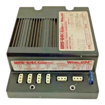
The Model UPS-64C™ Strobe Light Power Supply is a multiple outlet
power supply, to be mounted in areas protected from the weather
and abuse. The electronics of the power supply are enclosed inside a
weather resistant (not waterproof) powder coated die cast aluminum
housing.
MOUNTING THE UPS-64C:
1.
Install the unit with the strobe light connections located in such
a way that they are easily accessible.
IMPORTANT: THE UPS-64C IS NOT WATERPROOF.
2.
Install the unit with the four supplied #10 sheet metal screws on
a metal surface to provide adequate heat dissipation (See
important warning on page 3).
3 POSITION
STROBE LIGHT
CONNECTORS
3 POSITION
CONTROL
CONNECTOR
3 POSITION
POWER INPUT
CONNECTOR.
3.
Fit the supplied 3 pin AMP connectors on the pins located on
the end of the cables connected to the remote strobe light head
assemblies, (Fig. 2) and insert into the proper strobe light
outlets to conform to the desired strobe light system (See Pg. 4
& 5).
4.
Connect the power supply to power source via a desired control
switching system. (See Pg. 4 & 5)
CONNECTING THE AMP 3 PIN CONNECTOR HOUSINGS
TO THE CABLES OF THE REMOTE STROBE LIGHT
HEAD ASSEMBLIES:
The Whelen remote strobe light head assemblies are supplied with a
3 conductor cable mounted to the units. On the end of each one of
these cables are three pins factory crimped onto each of the three
wires. After cables have been properly installed and routed, these
pins will have to be inserted into the AMP 3 pin housings enclosed in
the mounting kit. (Fig. 2).
NOTE: IT IS IMPORTANT TO OBSERVE PIN LOCATIONS &
ORDER OF COLOR ON AMP 3 PIN CONNECTORS.
©1998 Whelen Engineering Company.
Form No.13290A (010798)
®
Fig. 1
15 AMP FUSE
FOR STROBE
POWER SUPPLY
PROTECTION
For warranty information regarding this product, visit www.whelen.com/warranty
Page 1
NOTE: THIS RIDGE INDICATES LOCATION OF POSITION NUMBER 1
AMP 3 PIN CONNECTOR HOUSING.
Once these AMP 3 pin connectors are properly connected onto
the cables of the remote strobe light head assemblies, the
remote strobe light head assemblies are ready to be plugged
into the 3 position socket strobe light connectors located on the
Model UPS-64C™ Power Supply (Figs. 1 & 5).
CONTROL WIRE HARNESS ASSEMBLY:
The Control wire harness assembly consists of an AMP 3 pin
connector with 2 wires, green and blue (See Figures 3 & 5). The
green wire controls the strobe light outlets 1, and 4, the blue
wire controls the strobe light outlets 2 and 3. This Control
harness assembly is to be connected to the 3 position socket
control connector located on the UPS-64C strobe light power
supply (See Figures 1 & 5). This control harness assembly is to
be crimped to a customer supplied control cable, which in turn is
to be connected to a customer supplied switch to complete the
installation.
GREEN WIRE POSITIVE (+) IN POSITION 2
BLUE WIRE POSITIVE (+) IN POSITION 3
CONTROL WIRE HARNESS ASSEMBLY
POWER-INPUT WIRE HARNESS ASSEMBLY
This Power-Input wire harness is to be connected to the 3
position socket Power-Input connector located on the power
supply (See Figures 1 & 5). The Power-Input wire harness
assembly consists of 2 wires, red and black (Fig. 4), and
functions to supply the power supply with power and controls
the 3 position strobe light connectors (Fig. 5).
Installation Guide:
Strobe Power Supply
Model UPS-64C™
RED WIRE (ANODE) IN POSITION 1
BLACK WIRE (CATHODE) IN POSITION 2
WHITE WIRE (TRIGGER) IN POSITION 3
Fig 2
Fig. 3
Advertisement

Related Manuals for Whelen Engineering Company UPS-64C


Summary of Contents for Whelen Engineering Company UPS-64C
-
Page 1: Installation Guide
WARNING: This product can expose you to chemicals including Lead which is known to the State of California to cause cancer and birth defects or other reproductive harm. For more information go to www.P65Warnings.ca.gov. The Model UPS-64C™ Strobe Light Power Supply is a multiple outlet NOTE: THIS RIDGE INDICATES LOCATION OF POSITION NUMBER 1... - Page 2 Connect the 3 pin position AMP housings to the cables of the remote strobe light head assemblies and plug into the appropriate 3 position socket strobe light connectors on the UPS-64C™ (See Pg. 4 for Strobe Light Flashing Configu- ration Options). Connect the UPS-64C™ to the power source through a switching control (See Figs.
-
Page 3: Important Note
CAUTION: Reversing polarity during WARNING: The Strobe Light Power Supply is a high installation (reversing positive voltage voltage device. Do not touch or remove tube assembly wires and ground wires) will blow the in strobe light head assemblies while in operation. 15 amp fuse incorporated into the unit. -
Page 4: Light System
Alternating flashing sequence The Model UPS-64C outlet strobe light flashing sequence SIMULTANEOUS variations are controlled by three factors: controlled by blue wire on control FLASHING harness, Pin # 3. SIMULTANEOUS Selecting one of the four wiring and control switchings Alternating flashing sequence FLASHING available for the system as described in diagrams shown. - Page 5 On this page, two selective switching variations with strobe light operating modes are illustrated. The final strobe light system depends on the loc- ation assigned to each remote strobe light head assembly and its type. (360° or directional units) IMPORTANT GENERAL NOTES: FUSES: All fuses shown in the wiring diagram below are customer supplied and recommended...
Need help?
Do you have a question about the UPS-64C and is the answer not in the manual?
Questions and answers