Advertisement
Quick Links
ENGINEERING COMPANY INC.
51 Winthrop Road
Chester, Connecticut 06412-0684
Phone: (860) 526-9504
Fax: (860) 526-4078
Internet: www.whelen.com
Sales e-mail: autosale@whelen.com
Canadian Sales e-mail: autocan@whelen.com
Customer Service e-mail: custserv@whelen.com
Safety First
This document provides all the necessary information to allow your Whelen product to be properly and safely installed.
Before beginning the installation and/or operation of your new product, the installation technician and operator must
read this manual completely. Important information is contained herein that could prevent serious injury or damage.
•
Proper installation of this product requires the installer to have a good understanding of automotive
electronics, systems and procedures.
•
If mounting this product requires drilling holes, the installer MUST be sure that no vehicle components or
other vital parts could be damaged by the drilling process. Check both sides of the mounting surface
before drilling begins. Also de-burr any holes and remove any metal shards or remnants. Install grommets
into all wire passage holes.
•
If this manual states that this product may be mounted with suction cups, magnets, tape or Velcro®, clean
the mounting surface with a 50/50 mix of isopropyl alcohol and water and dry thoroughly.
•
Do not install this product or route any wires in the deployment area of your air bag. Equipment mounted
or located in the air bag deployment area will damage or reduce the effectiveness of the air bag, or
become a projectile that could cause serious personal injury or death. Refer to your vehicle owner's
manual for the air bag deployment area. The User/Installer assumes full responsibility to determine proper
mounting location, based on providing ultimate safety to all passengers inside the vehicle.
•
For this product to operate at optimum efficiency, a good electrical connection to chassis ground must be
made. The recommended procedure requires the product ground wire to be connected directly to the
NEGATIVE (-) battery post.
•
If this product uses a remote device to activate or control this product, make sure that this control is
located in an area that allows both the vehicle and the control to be operated safely in any driving
condition.
•
Do not attempt to activate or control this device in a hazardous driving situation.
•
It is recommended that these instructions be stored in a safe place and referred to when performing
maintenance and/or reinstallation of this product.
•
FAILURE TO FOLLOW THESE SAFETY PRECAUTIONS AND INSTRUCTIONS COULD RESULT IN DAMAGE
TO THE PRODUCT OR VEHICLE AND/OR SERIOUS INJURY TO YOU AND YOUR PASSENGERS!
For warranty information regarding this product, visit www.whelen.com/warranty
©1998 Whelen Engineering Company Inc.
Form No.13306B (072507)
®
Page 1
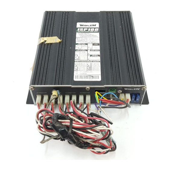
Installation Guide:
Model ISP188
Intelligent Strobe Power Supply
Advertisement

Subscribe to Our Youtube Channel
Related Manuals for Whelen Engineering Company ISP188


Summary of Contents for Whelen Engineering Company ISP188
-
Page 1: Safety First
FAILURE TO FOLLOW THESE SAFETY PRECAUTIONS AND INSTRUCTIONS COULD RESULT IN DAMAGE TO THE PRODUCT OR VEHICLE AND/OR SERIOUS INJURY TO YOU AND YOUR PASSENGERS! For warranty information regarding this product, visit www.whelen.com/warranty ©1998 Whelen Engineering Company Inc. Form No.13306B (072507) Page 1... -
Page 2: Operating Instructions
Dip Switch 2 - OFF Dip Switch 8 - OFF only the 8 outlets on the ISP188, but of the strobe light and strobe cable connected to these outlets as well. Each LED indicator on the Diagnostix display, provides Control Wires diagnostic information for one outlet. -
Page 3: Wiring Diagram
In this condition, further investigation of the components is strongly recommended Sequential ON continuously ModuFlash™ with a single flash The ISP188 is operating in Lo power mode. MicroBurst II™ every few seconds MicroBurst III™ Table 3 2X CometFlash® 2X TripleFlash™... - Page 4 In order for the Traffic Advisor patterns to flash properly, 46-9641638250 25' TWISTED PAIR B-LINK CABLE it is necessary for the lamps to be connected to the 46-0725612-00 POWER CONNECTOR ASSEMBLY ISP188 in the following pattern. 02-0241485-25 CABLE ASSY, 8 POS TELEPHONE 25' 01-0267643-00 DOT DIAGNOSTIC INDICATOR ASSEMBLY LEFT...
Need help?
Do you have a question about the ISP188 and is the answer not in the manual?
Questions and answers