Advertisement
Quick Links
ENGINEERING COMPANY INC.
Route 145, Winthrop Road,
Chester, Connecticut 06412
Phone: (860) 526-9504
Fax: (860) 526-2009
Internet: www.whelen.com
Sales/Service e-mail: aviation@whelen.com
Specifications:
Position Lights -
Current Draw ................ 4.0 Amps @ 14 Volts D.C.
Weight........................... 1.7 lbs.
Length........................... 5.00"
Width............................. 3.12"
Height ........................... 3.06"
INSTALLATION PROCEDURES...
Mounting Location
1.
Consider areas or locations designated by the aircraft
manufacturer. Do not mount the strobe power supply
closer than three (3) feet of the ADF loop.
2.
For alternate locations, consider areas such as the
cabin baggage compartment, the floor under the seat,
non-structural bulkheads, firewalls, etc..
3.
If necessary, fabricate support brackets or shelves, and
attach them to the aircraft structure to provide a
mounting surface that will withstand the inertia forces
stipulated in chapters 1 & 3 of AC 43.13-2A.
4.
An "IA" or other representative of the FAA must approve
documentation of structural integrity of the fabricated
installation.
5.
When installing the strobe light power supply in an
inverted position, drill a 3/16" diameter hole in the lowest
corner of the cover to provide for moisture drainage.
Care must be taken not to let the drill protrude into the
power supply, for it will inflict damage to the electronic
components.
6.
Specifically call out the location of the strobe light power
supply of FAA form 337.
OUTPUT
POWER
1 - Anode
1 - (+)
2 - Cathode
2 - (-)
3 - Trigger
3 - SYNC
1
1
2
2
3
3
©2001 Whelen Engineering Company Inc.
Form No.13610A (030303)
®
2.0 Amps @ 28 Volts D.C.
POS. 1 (+), RED
POS. 2 (-), BLACK
POS. 3 - SYNC
Page 1
Operation:
This power supply will operate ONE strobe light
head assembly at 34 joules of power. It is equipped
to flash up to five (5) other like units simultaneously
when an 18 gage wire is connected to outlet 3 on the
input power connector.
Wiring Instructions
WARNING! STROBE LIGHT POWER SUPPLIES ARE
POLARITY SENSITIVE. REVERSING THE
INPUT POLARITY WILL CAUSE SEVERE
DAMAGE TO THE POWER SUPPLY!
Steps below: "Ref. AC 43.13-1B, Chapter 11, Sections 1, 2, 3 & 7".
1.
Choosing wire size of A+ input lead, refer to Paragraph 444
"Electric Wire Chart" Figure 11.7 & 11.7A, with reference to
"Strobe Light Model Current" requirement chart on page 6 &
11, and "Wire and Circuit Protection Chart" Figure 11.1.
2.
Shielded wire is not generally necessary, but has proven
effective in reducing the possibility of radio interference.
3.
The power supply shall acquire its power from a low
impedance source such as the alternator or generator end of
the electrical buss as close to the battery as possible.
4.
For penetrating pressure hull, refer to the aircraft service
manual.
5.
Check all avionics systems for interference.
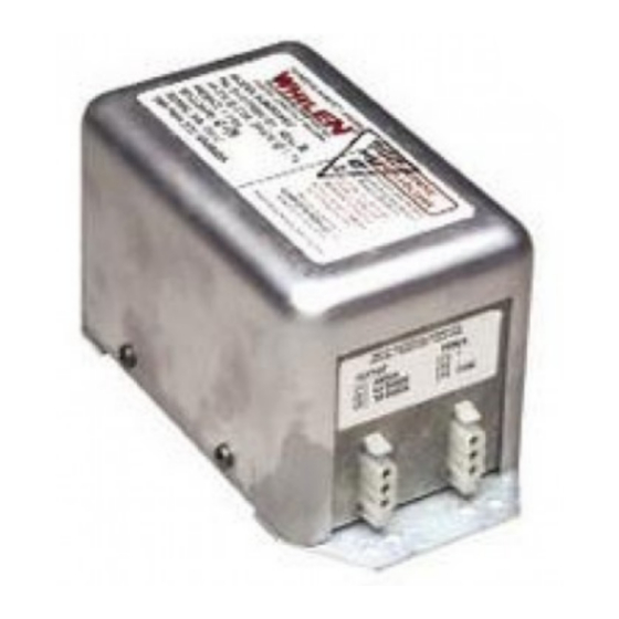
Looking at the power supply connectors with the mounting plate
flat on a bench, the left connector is the strobe outlet. The right
connector is the power input and synchronization.
Left Connector (Power Output)
Pin 1. (Top)
-
RED wire/anode
Pin 2. (Center) -
BLACK wire/cathode
Pin 3. (Bottom)-
WHITE wire/trigger
Right Connector (Power Input)
Pin 1. (Top)
-
RED wire/13 to 30 volt, positive input
Pin 2. (Center) -
BLACK wire/ground
Pin 3. (Bottom)-
Synchronization pin/If synchronization is
desired, connect an 18 gage wire between
pin 3 on each power supply.
Installation Guide:
Model A490ATSC
P/N 01-0770062-03
Strobe Power Supply
(FAA/PMA Approved)
Advertisement

Related Manuals for Whelen Engineering Company A490ATSC


Summary of Contents for Whelen Engineering Company A490ATSC
-
Page 1: Installation Guide
Pin 3. (Bottom)- Synchronization pin/If synchronization is POS. 1 (+), RED desired, connect an 18 gage wire between POS. 2 (-), BLACK pin 3 on each power supply. POS. 3 - SYNC ©2001 Whelen Engineering Company Inc. Form No.13610A (030303) Page 1... - Page 2 INTERCONNECTING CABLE... IMPORTANT NOTE: The Whelen interconnecting cable shall be secured in place Your new strobe power supply has an additional circuit built-in to prevent with approved aviation techniques. self-ionization (steady glowing) of the strobe tubes. In some cases, when replacing older power supplies, the bare shield wire in the existing The cable shall not parallel ADF, Gyro or Flux Gate compass harness is pinned together at each end with the black wire.
Need help?
Do you have a question about the A490ATSC and is the answer not in the manual?
Questions and answers