Table of Contents
Advertisement
APRILIA WOULD LIKE TO THANK YOU
for choosing one of its products. Please read this manual carefully before riding your vehicle for the first time. It contains information, suggestions and
precautions on the use of your vehicle and it will allow you to get familiar with all its different characteristics. It will also help to get the maximum result
and pleasure from your purchase and it will confirm you one more time that you have made the right choice. This booklet is an integral part of the vehicle
and must be given to the new owner if the motorcycle is sold.
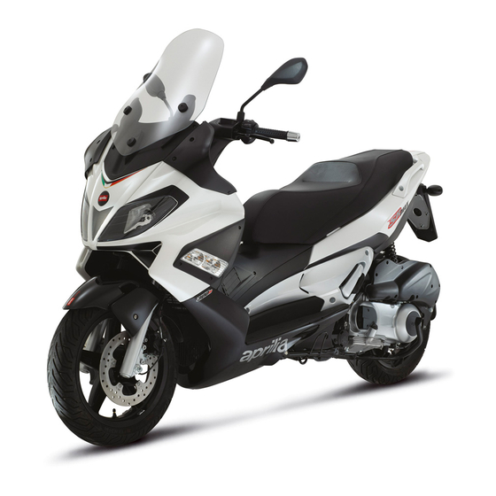
SR MAX 300 i.e.
Ed. 01_05/2014
Advertisement
Table of Contents

Related Manuals for APRILIA SR MAX 300 i.e.


Summary of Contents for APRILIA SR MAX 300 i.e.
- Page 1 APRILIA WOULD LIKE TO THANK YOU for choosing one of its products. Please read this manual carefully before riding your vehicle for the first time. It contains information, suggestions and precautions on the use of your vehicle and it will allow you to get familiar with all its different characteristics. It will also help to get the maximum result and pleasure from your purchase and it will confirm you one more time that you have made the right choice.
- Page 2 The instructions given in this booklet are intended to provide a clear, simple guide to using your scooter; it also describes routine maintenance procedures and regular checks that should be carried out on the vehicle at an Aprilia Dealer or Authorised Workshop. This booklet also contains instructions for simple repairs.
- Page 3 Personal safety Failure to completely observe these instructions will result in serious risk of personal injury. Safeguarding the environment Sections marked with this symbol indicate the correct use of the vehicle to prevent dam- aging the environment. Vehicle intactness The incomplete or non-observance of these regulations leads to the risk of serious damage to the vehicle and sometimes even the invalidity of the guarantee The signs that you see on this page are very important.
-
Page 5: Table Of Contents
INDEX VEHICLE..................Running in................. 34 Dashboard................Starting up the engine............... 34 Instruments................11 Precautions................36 Indicator unir................11 Difficult start up................. 37 Clock..................12 Stopping the engine..............37 Digital lcd display..............13 Stand..................37 Maintenance icons..............14 Automatic transmission............. 38 Setting the total and trip odometers........ - Page 6 Rear-view mirrors..............66 Front and rear disc brake............67 Puncture..................68 Inactivity of the vehicle.............. 69 Cleaning the vehicle..............69 TECHNICAL DATA..............75 Kit equipment................80 SPARE PARTS AND ACCESSORIES........81 Warnings................... 82 PROGRAMMED MAINTENANCE..........85 Scheduled maintenance table........... 86...
-
Page 7: Vehicle
SR MAX 300 i.e. Chap. 01 Vehicle... - Page 8 01_01...
-
Page 9: Dashboard
Dashboard (01_01) A = Ignition key-switch B = Starter button C = Throttle grip D = Front brake lever E = «Mode» remote switch F = Emergency cut-off switch G= Digital instrument panel H = Warning light unit on digital instrument panel I = Analogue instrument panel L = Passing M = Rear brake lever... - Page 10 01_02...
-
Page 11: Instruments
Instruments (01_02) A = Rpm indicator B = Speedometer with twin scale (km/h and mph) C = Engine control warning light D = Low fuel warning light M = Low oil pressure warning light F = Turn indicator warning light G = Antitheft device LED H = LCD Display I = «Odo/Set»... -
Page 12: Clock
B = Headlight warning light C = High-beam warning light D = Warning light pre-installation Clock (01_04) Pushing the «CLOCK» button for less than 1 second displays the following sequence: • TIME • DATE • TOTAL/PARTIAL To set the clock push and hold the «CLOCK» button longer than 3 seconds. The numbers showing the hours will begin flashing. -
Page 13: Digital Lcd Display
01_05 Digital lcd display (01_05) A = «SERVICE» maintenance icon B = «BELT» maintenance icon C = Battery Icon D = Miles/gallons icon (Not used) E = 3-digit display F = Fuel gauge... -
Page 14: Maintenance Icons
G = Miles per hour icon H = Total odometer indicator I = Partial odometer indicator L = «ODO/SET» button M = Km/h gauge N = «CLOCK» button O = 5-digit display P = «MODE» button Q = Maximum speed indicator R = Mean speed S = Water temperature gauge Maintenance icons (01_06) -
Page 15: Setting The Total And Trip Odometers
Setting the total and trip odometers By pressing the button «L» ODO/SET, the display shifts from total to trip odometer. Hold down the button «L» ODO/SET for more than 3 seconds to reset the trip odom- eter, mean speed and maximum speed gauges. Setting the date function (01_07) Set «DATE»... -
Page 16: Key Switch
NOTE - MEAN SPEED IS CALCULATED JUST BY TURNING THE KEY TO «ON» AND THE ENGINE HAS TO BE OVER 800 RPM. - TO SHIFT FROM km/h TO mp/h: HOLD DOWN THE «MODE» AND «CLOCK» BUTTONS SIMULTANEOUSLY, WITH THE KEY SET TO «OFF». THEN TURN THE KEY TO «ON»... -
Page 17: Locking The Steering Wheel
LOCK «3»: Ignition disabled, extractable key, mechanical antitheft device enabled. SADDLE OPENING«4»: Set this position by pressing the key set to OFF and turning it clockwise. Locking the steering wheel Turn the handlebar to the left (as far as it will go), turn the key to «LOCK» and remove the key. -
Page 18: Switch Direction Indicators
Switch direction indicators (01_11) Lever «O» towards «1» = left turn indicators switched on; Lever «O» towards «2» = right turn indicators switched on; The lever «O» automatically goes back to its «0» position and the indicators remain on; push the lever «O» to turn them off. Horn button (01_12) Push the button «P»... -
Page 19: Start-Up Button
Start-up button (01_14) To start the engine, pull either one of the two brake levers and press the starter button «B». 01_14 Engine stop button (01_15) The engine can be started when the emergency cut-off switch «F» is set to «1» RUN;... -
Page 20: Accessing The Fuel Tank
Accessing the fuel tank (01_16) To remove the fuel tank cover «A» lift tab «B» and insert the key in lock «C». 01_16 The immobilizer system In order to enhance theft protection, the vehicle is equipped with a «PIAGGIO IMMO- BILIZER »... -
Page 21: Immobilizerdevice Enabled Indicator Led
WARNING LOSING THE RED-HANDGRIP KEY AVOIDS ANY FURTHER REPAIR OF THE "PIAGGIO IMMOBILIZER" SYSTEM AND OF THE ENGINE CONTROL UNIT. WARNING KEEP THE RED-HANDGRIP KEY IN A SAFE PLACE (NOT ON THE VEHICLE). Immobilizerdevice enabled indicator led (01_18) Activation of the «PIAGGIO IMMOBILIZER» system is signalled by a flashing «G» warning light. -
Page 22: Programming The Immobilizer System
ment required to detect and repair the system. The immobilizer is also activated when the emergency cut-off switch stops the engine or the side stand is lowered. This hap- pens even if the starter key is in «ON». When additional keys are required, please note that data storage (up to 7 keys max.) must be done on all keys, both new and existing ones. -
Page 23: Power Supply Socket
Intermediate step - black key After pulling out the red key, insert the black key within 10 seconds and promptly turn it to «ON». After 1-3 seconds, turn the key to «OFF» again and pull it out. In this way, a maximum of 7 black keys can be programmed by repeating the above procedure keeping the indicated times. -
Page 24: The Saddle
Electric characteristic Plug socket 12 V - 180 W MAX The saddle (01_20) To lift the saddle and get access to the helmet compartment, insert the key in the key switch «A». With the key set to «OFF», push it and turn it anticlockwise to the «SAD- DLE OPENING»... -
Page 25: Adjusting The Windscreen
Adjusting the windscreen (01_21, 01_22) The windshield can be adjusted to 3 positions «B», «C» and «D» according to the rider's needs. Unscrew the 3 screws «A», remove the windshield upper part and set it in the desired position. Tighten the 3 fixing screws again. WARNING CARRY OUT THIS OPERATION WITH EXTREME CARE SO AS NOT TO 01_21... - Page 26 CAUTION BE REMINDED THAT ALTERING IDENTIFICATION REGISTRATION NUMBERS CAN LEAD TO SERIOUS PENAL SANCTIONS (IMPOUNDING OF THE VEHICLE, ETC.). Chassis number To read the chassis number, remove the lid «A» in the helmet compartment. Engine number The engine number «B» is stamped near the rear left shock absorber lower support. 01_23...
- Page 27 01_24...
-
Page 29: Use
SR MAX 300 i.e. Chap. 02... -
Page 30: Checks
02_01 Checks (02_01) Before using the vehicle, check: 1. That the fuel tank is full. 2. The front and rear brake fluid level. 3. That the tyres are properly inflated. 4. The correct functioning of side lights, headlamp, turn indicators, stop light and li- cense plate light. -
Page 31: Refuelling
Refuelling (02_02) Reach the fuel tank and unscrew the cap «A». Use premium unleaded petrol, with minimum octane rating of 95. A specific gauge on the instrument panel indicates the fuel level. WARNING 02_02 SWITCH OFF THE ENGINE BEFORE REFUELLING WITH PETROL. PETROL IS HIGHLY INFLAMMABLE. -
Page 32: Tyre Pressure
Tyre pressure (02_03) Check tyre pressure frequently. Tyres feature wear indicators; replace tyres as soon as these indicators become visible on the tyre tread. Also check that the tyres do not show signs of splitting at the sides or irregular tread wear; if this occurs, go to an authorised workshop or at least to a workshop equipped to perform the replacement. -
Page 33: Shock Absorber Adjustment
Shock absorber adjustment (02_04, 02_05) The preloading of the springs can be adjusted to 4 positions acting on the ring nut located in the lower part of the shock absorbers with the specific spanner supplied. Position 1: minimum preload: rider only Position 2 medium preloading: rider only Position 3 medium preloading: rider and passenger Position 4: maximum preloading: rider, passenger, and luggage. -
Page 34: Running In
Running in (02_06) WARNING DURING THE FIRST 1000 KM DO NOT RIDE THE VEHICLE OVER 80% OF ITS MAXIMUM SPEED. AVOID TWISTING THE THROTTLE GRIP FULLY OR KEEP- ING A CONSTANT SPEED ALONG LONG SECTIONS OF ROAD. AFTER THE FIRST 1000 KM, GRADUALLY INCREASE SPEED UNTIL REACHING THE MAX- IMUM PERFORMANCE. - Page 35 WARNING THE AUTOMATIC TRANSMISSION MAKES THE REAR WHEEL TURN EVEN WHEN THE THROTTLE IS SLIGHTLY TWISTED. RELEASE THE BRAKE CARE- FULLY AFTER STARTING, AND THEN ACCELERATE GRADUALLY. CAUTION 02_08 DO NOT START-UP THE ENGINE IN CLOSED AREAS BECAUSE EXHAUST GASES ARE TOXIC. 02_09 02_10...
-
Page 36: Precautions
Precautions CAUTION NEVER STRESS THE ENGINE AT LOW TEMPERATURES IN ORDER TO AVOID POSSIBLE DAMAGE. BE CAREFUL NEVER TO EXCEED THE MAXIMUM SPEED WHILE RUNNING DOWNHILL, IN ORDER TO AVOID DAMAGING THE ENGINE. IN ANY CASE, IN ORDER TO PRESERVE THE ENGINE FROM PROLONGED OVERREVVING, THE REVOLUTION LIMITER WILL BE ACTIVATED IF THE EN- GINE SPEED EXCEEDS THE ESTABLISHED THRESHOLD. -
Page 37: Difficult Start Up
Difficult start up (02_11) Should there be any problem, proceed as follows: 1. Check that the spark plug is working properly; 2. Check that there is enough fuel in the fuel tank; when there is no more fuel left, refill the tank and start the vehicle by pressing button «B» and keeping the throttle grip slightly twisted. -
Page 38: Automatic Transmission
SIDE STAND Push with your foot on the fork of the stand "L" to bring it into the open position while lifting the scooter at the same time. CAUTION TAMPERING MAY CAUSE SERIOUS ENGINE MALFUNCTION. 02_13 WARNING THE SIDE STAND CAUSES THE ENGINE TO TURN ITSELF OFF WHENEVER IT IS LOWERED. -
Page 39: Safe Driving
1. Do not continue riding in such conditions. 2. Let the clutch cool down with the engine at idle speed for a few minutes. Safe driving (02_15) Some simple tips are provided below that will enable you to use your vehicle on a daily basis in greater safety and peace of mind. - Page 40 IN ORDER TO PREVENT ANY ACCIDENTS RIDE VERY CAREFULLY AFTER ADDING ACCESSORIES AND WHILE CARRYING LUGGAGE. THE ADDITION OF ACCESSORIES AND LUGGAGE CAN REDUCE YOUR SCOOTER STABILITY AND PERFORMANCE, AS WELL AS THE LEVEL OF SAFETY DURING USE. NEVER RIDE FASTER THAN 100 km/h WITH A SCOOTER WITH ADDED AC- CESSORIES .
-
Page 41: Maintenance
SR MAX 300 i.e. Chap. 03 Maintenance... -
Page 42: Engine Oil Level
Engine oil level In 4-stroke engines, engine oil is used to lubricate the distribution elements, the bush- es and the thermal group. An insufficient quantity of oil can cause serious damage to the engine.In all four-stroke engines, a loss of efficiency in oil performance and certain consumption should be considered normal. -
Page 43: Engine Oil Top-Up
Engine oil top-up Any topping up with oil must be carried out after oil level check and by adding oil, but never exceeding the MAX level. The topping up of the level between MIN and MAX requires approx. 400 cm³ of oil. According to the instructions in the scheduled maintenance tables, engine oil level should be checked and topped up, if necessary, at an Authorised Piaggio Service Centre. - Page 44 WARNING RUNNING THE ENGINE WITH INSUFFICIENT LUBRICATION OR WITH INADE- QUATE LUBRICANTS ACCELERATES THE WEAR AND TEAR OF THE MOVING PARTS AND CAN CAUSE IRREVERSIBLE DAMAGE. WARNING EXCESSIVE OIL LEVEL AT TOP-UPS CAN LEAD TO SCALE FORMATION AND VEHICLE MALFUNCTION. CAUTION USED OILS CONTAIN SUBSTANCES HARMFUL TO THE ENVIRONMENT.
-
Page 45: Hub Oil Level
Hub oil level (03_04, 03_05) Make sure there is oil in the rear hub according to the intervals specified in the sched- uled maintenance table. To check the rear hub oil level, proceed as follows: 1) Rest the vehicle onto its centre stand, on level ground. 2) Unscrew the dipstick «A», dry it with a clean cloth and then reinsert it screwing it fully into place. - Page 46 CAUTION AN EXCESSIVE QUANTITY OF OIL CAN LEAD TO SPILL OVER, WHICH MAY CAUSE THE ENGINE AND THE WHEEL TO GET DIRTY. CAUTION WHEN REPLACING THE HUB OIL DO NOT LET THE OIL COME INTO CONTACT WITH THE REAR BRAKE DISC. CAUTION FOR OIL REPLACEMENT, CONTACT ANY AUTHORISED SERVICE CENTRE AS THEY ARE EQUIPPED TO DISPOSE OF USED OILS IN AN ENVIRONMENTALLY...
-
Page 47: Tyres
Tyres (03_06) Check tyre pressure and wear frequently. Tyres feature wear indicators; replace tyres as soon as these indicators become visi- ble on the tyre tread. Also check that the tyres do not show signs of splitting at the side or irregular tread wear;... -
Page 48: Spark Plug Dismantlement
TYRE INFLATION PRESSURE Front tyre pressure 2.1 bar Rear tyre pressure 2.4 bar Spark plug dismantlement (03_07, 03_08, 03_09) Proceed as follows: 1. Lift the rubber mat; 2. Remove the right side cover by unscrewing the three screws «A»; 3. Disconnect spark plug HV wire cap «B» ; 4. -
Page 49: Removing The Air Filter
Characteristic Spark plug NGK CR8EKB Electric characteristic Electrode gap 0.7 to 0.8 mm 03_09 Locking torques (N*m) Spark plug 12 ÷ 14 Removing the air filter (03_10) Proceed as follows: 1. Unscrew the 9 fixing screws «A»; 2. Remove the cover «B» in order to take out the sponge. CAUTION 03_10 IF THE VEHICLE IS USED ON DUSTY ROADS IT IS NECESSARY TO CARRY OUT... -
Page 50: Air Filter Cleaning
Air filter cleaning (03_11) 1. Wash the sponge with water and neutral soap. 2. Dry it with a clean cloth and small blasts of compressed air. 3. Soak the sponge with a mixture of 50% petrol and 50% specified oil. 4. - Page 51 Check coolant when the engine is cold as indicated in the scheduled maintenance table, following the steps below. a) Place the scooter in a vertical position on the stand. b) Remove the expansion tank cover «A», turning in anticlockwise. c) Look inside the expansion tank: reference «C» shows the adequate coolant level. d) If the coolant level is below reference «C», proceed to top-up when the engine is cold.
-
Page 52: Checking The Brake Oil Level
Recommended products AGIP PERMANENT SPECIAL Ethylene glycol-based antifreeze fluid with organic inhibition additives. Red, ready for ASTM D 3306 - ASTM D 4656 - ASTM D 4985 - CUNA NC 956-16 Checking the brake oil level (03_15) The front and rear brake fluid reservoirs are both positioned on the handlebar. Proceed as follows: 1. - Page 53 WARNING ONLY USE DOT 4-CLASSIFIED BRAKE FLUID. BRAKE CIRCUIT FLUID IS VERY CORROSIVE; MAKE SURE THAT IT DOES NOT COME INTO CONTACT WITH THE PAINTWORK. CAUTION AVOID CONTACT OF BRAKE FLUID WITH EYES, SKIN, AND CLOTHING. IN CASE OF ACCIDENTAL CONTACT, RINSE WITH WATER. THE FLUID IN THE BRAKING CIRCUIT IS HYGROSCOPIC, THAT IS, IT ABSORBS MOISTURE FROM THE SURROUNDING AIR.
-
Page 54: Battery
Battery (03_17, 03_18) To access the battery, proceed as follows: 1. Rest the vehicle on its centre stand; 2. Open the saddle following the above instructions, see the «Saddle» section; 3. Remove the piston ring «A» and take off the battery cover. The battery is the electrical device that requires the most frequent inspections. -
Page 55: Long Periods Of Inactivity
Long periods of inactivity (03_19) Battery performance will decrease if the vehicle is not used for a long time. This is the result of the natural phenomenon of battery discharging, and may be due to residual absorption by vehicle components with constant power consumption. Poor battery performance may also be due to environmental conditions and the cleanness of the poles. -
Page 56: Fuses
Fuses (03_20, 03_21, 03_22) The electric system is fitted with 2 fuse boxes: 1. Fuse box «A» 5 fuses located in the helmet compartment near the battery. 2. Fuse box «B» 6 fuses located in the helmet compartment near the plug socket. - Page 57 bulb, Lines protected by fuses No. 8 and 9 Fuse No. 3 Capacity:15 A Protected circuits:Radiator electric fan Fuse No. 4 Capacity:15 A Protected circuits:Lines protected by fuses No. 6, 7, 10 and Fuse No. 5 Capacity:10 A Protected circuits:electronic control unit, water pump, H.V.
- Page 58 FUSE BOX B Fuse No. 6 Capacity:7.5 A Protected circuits:Low beam light bulb Fuse No. 7 Capacity:7.5 A Protected circuits:High beam light bulb, High beam remote control, High beam warning light Fuse No. 8 Capacity:7.5 A Protected circuits:Immobilizer, ECU, ECU remote control, radiator electrovalve remote control, turn indicator bulbs, digital instrument panel,...
- Page 59 Protected circuits: Horn button, stop light bulb, engine start up circuit BULBS High/low beam light bulb Type: Halogen (H7) Power: 12V - 55W Quantity: 2 Front headlights bulb Type: Incandescent (W2.1 x 9.5 D) Power: 12V - 5W Quantity: 2 Rear turn indicator bulbs Type: Incandescent (BAU 155 ) Power: 12V-10W...
-
Page 60: Front Light Group
Front light group (03_23, 03_24, 03_25, 03_26, 03_27) To access the bulbs, proceed as follows: 1. Pull the aprilia clip-on badge off with a plain slot screwdriver. 2. Remove the legshield connection by undoing the two screws «A». 3. Remove the four screws «B». - Page 61 03_24 03_25 03_26...
-
Page 62: Headlight Adjustment
03_27 Headlight adjustment (03_28, 03_29) Proceed as follows: 1. Position the vehicle in running order and with the tyres inflated to the prescribed pressure, onto a flat surface 10 m away from a half-lit white screen; ensure that the longitudinal axis of the vehicle is perpendicular to the screen; 2. -
Page 63: Front Direction Indicators
Turn the screw «A» clockwise to lower the light beam, turn the set screw «A» anti- clockwise to raise the light beam. Front direction indicators (03_30, 03_31) To replace the burnt out bulb remove the 3 screws «A » shown in the figure, and then take the rubber holder off its socket;... -
Page 64: Rear Turn Indicators
Rear turn indicators (03_32) Undo the screw «A», then remove the glass «B». 03_32 Number plate light (03_33) Remove the screw «C», then take out the bulb holder. 03_33... -
Page 65: Helmet Compartment Lighting Bulb
Helmet compartment lighting bulb (03_34) Open the helmet compartment, take out the pressure mounted glass cover «F» and replace the bulb. 03_34 Brake light (03_35, 03_36, 03_37) To remove the Stop Light and Tail Light bulb, proceed as follows: 1. Open the saddle and remove the rear cover by undoing the two screws «A» 2. -
Page 66: Rear-View Mirrors
03_37 Rear-view mirrors (03_38, 03_39) To adjust mirrors, loosen the lock nut «A», place the mirror stem adequately and tighten the lock nut. The rear-view mirror is assembled on a stem with a ball 'joint'. The mirror can be adjusted to the desired position manually. 03_38 03_39... -
Page 67: Front And Rear Disc Brake
Front and rear disc brake (03_40) The brake disc and pad wear is automatically compensated, therefore it does not have any effect on brake functioning. For this reason it is not necessary to adjust the brakes. An excessively elastic brake lever stroke may indicate the presence of air in the brake circuit or a failure in the braking system. -
Page 68: Puncture
Puncture (03_41) The vehicle is equipped with Tubeless tyres (without inner tubes). In the event of a puncture, Tubeless tyres - unlike tyres with inner tubes - go flat very slowly, resulting in a greater steering safety. A flat tyre can be repaired with an emergency «inflate and repair»... -
Page 69: Inactivity Of The Vehicle
Inactivity of the vehicle (03_42) We recommend carrying out the following operations: 1. Clean the vehicle thoroughly and then cover it with a canvas; 2. With the engine off and the piston in the bottom dead centre position, remove the spark plug, and pour into its hole 1 t0 2 cc of the recommended oil. - Page 70 CAUTION DETERGENTS CAN POLLUTE WATER. THE VEHICLE MUST BE WASHED AT A WASH STATION EQUIPPED WITH A SPECIAL WATER PURIFICATION SYSTEM. IF YOU WASH THE ENGINE WITH A HIGH-PRESSURE WATER JET MACHINE: • ONLY USE THE FAN JET. • DO NOT PLACE THE WATER JET NOZZLE CLOSER THAN 60 CM. •...
- Page 71 STARTING FAILURE Emergency switch in «OFF» Set the switch back to «ON» Side stand down Lift stand Fuse blown Replace the blown fuse and have the scooter checked by an Authorised Service Centre. STARTING DIFFICULTIES (SEE SECTION «START-UP PROBLEMS») Lack of fuel in tank. Refuelling Fuel pump fault Contact an Authorized Service...
- Page 72 IGNITION PROBLEM Faulty spark plug Contact an Authorised Service Centre LACK OF COMPRESSION Loose spark plug. Screw in the spark plug tightly Cylinder head loose, piston gas Contact an Authorised Service rings worn. Centre Valve stuck Contact an Authorised Service Centre HIGH CONSUMPTION AND LOW PERFORMANCE Air filter blocked or dirty.
- Page 73 INEFFICIENT SUSPENSIONS Shock absorber fault, oil leak, end Contact an Authorised Service buffer damaged; shock absorber Centre preloading incorrectly set IRREGULAR AUTOMATIC TRANSMISSION Variator rollers and/or driving belt Contact an Authorised Service damaged Centre STAND DOES NOT RETURN TO POSITION Presence of dirt Clean and grease...
-
Page 75: Technical Data
SR MAX 300 i.e. Chap. 04 Technical data... - Page 76 04_01...
- Page 77 VEHICLE TECHNICAL DATA Chassis Tubular and steel sheets. Front suspension Hydraulic telescopic fork with Ø 35- mm stem Rear suspension Two double-acting shock absorbers, adjustable to four positions at preloading. Front brake Ø 260-mm disc brake with hydraulic control activated by handlebar right-side lever.
- Page 78 ENGINE TECHNICAL DATA Type Single-cylinder, 4-stroke Engine capacity 278 cm³ Bore x Stroke 75x63 mm Compression ratio 11 ± 0.5 : 1 Idle speed 1700 ± 100 rpm Timing system 4 valves, single overhead camshaft, chain-driven. Valve clearance Intake: 0.10 mm Exhaust: 0.15 mm Max.
- Page 79 α/N three-dimensional map Ignition advance managed by control unit Spark plug NGK CR8EKB Fuel system Electronic injection with electric fuel pump Fuel Unleaded petrol (95 RON) Exhaust silencer Absorption-type exhaust muffler with catalytic converter. Emissions compliance EURO 3 CAPACITIES Engine oil 1.3 l Transmission oil 250 cm³...
-
Page 80: Kit Equipment
04_02 Kit equipment (04_02) • 16 mm box-spanner; • Twin screwdriver; • A pair of pliers to extract fuses. • Wrench for adjusting shock absorbers. The tools are stored in the helmet compartment. -
Page 81: Spare Parts And Accessories
SR MAX 300 i.e. Chap. 05 Spare parts and accessories... -
Page 82: Warnings
Warnings (05_01) WARNING TO PREVENT ACCIDENTS AND TO GUARANTEE PROPER STABILITY, PER- FORMANCE AND SAFETY, RIDE THE VEHICLE VERY CAREFULLY WHEN IT IS FITTED WITH ACCESSORIES OR WITH UNUSUAL LOADS. WARNING IT IS ALSO RECOMMENDED THAT ORIGINAL PIAGGIO SPARE PARTS BE USED, AS THESE ARE THE ONLY ONES OFFERING YOU THE SAME QUALITY GUARANTEE AS THOSE INITIALLY FITTED ON THE SCOOTER. - Page 83 BEFORE WITHIN THE LIMITS ESTABLISHED BY LAW. IF THERE ARE NOT PAIGE ACCESSORIES FITTED, OR AN ABNORMAL LOAD, OR IF THE VEHICLE IS NOT IN A GENERALLY GOOD CONDITION, OR WHENEVER WEATHER CON- DITIONS DEMAND IT, SPEED SHOULD BE FURTHER REDUCED. WARNING BE EXTREMELY CAREFUL WHEN INSTALLING AND REMOVING THE MECHAN- ICAL ANTITHEFT DEVICE ON THE VEHICLE (U-SHAPED PADLOCK, DISC...
-
Page 85: Programmed Maintenance
SR MAX 300 i.e. Chap. 06 Programmed maintenance... -
Page 86: Scheduled Maintenance Table
06_01 Scheduled maintenance table (06_01) Adequate maintenance is fundamental to ensure long-lasting, optimum operation and performance of your vehicle. For this purpose, PIAGGIO offers a set of checks and maintenance services (for pay- ment) which are included in the summary table shown on the following page. Any minor faults should be reported without delay to an Authorised Service Centre or Dealer without waiting until the next scheduled service to solve it. - Page 87 km x 1,000 Driving belt Throttle control Air filter Belt compartment air filter Oil filter Oil filter (mesh) Valve clearance Electrical system and battery Brake fluid * Coolant * Engine oil Hub oil Brake pads Sliding shoes / CVT rollers Tyre pressure and wear Vehicle road test Suspension...
- Page 88 Clean the SAS air filter every 2 years * Replace every 2 years RECOMMENDED PRODUCTS TABLE Product Description Specifications AGIP GEAR 80W-90 Oil for speed gearbox SAE 80W-90, API GL-4 mineral multigrade oil AGIP CITY HI TEC 4T Oil to lubricate flexible transmissions (throttle Oil for 4-stroke engines control) AGIP GP 330...
- Page 89 TABLE OF CONTENTS Accessories: 81 Fuel: 20 Light switch: 18 Tank: 20 Air filter: 49, 50 Fuses: 56 Technical data: 75 Transmission: 38 Turn indicators: 64 Tyre pressure: 32 Maintenance: 14, 41, 85, 86 Tyres: 47 Battery: 54 Headlight: 62 Maintenance Table: 86 Brake: 52, 65, 67 Helmet compartment: 65...
- Page 90 The reliability of the vehicle also depends on its mechanical conditions. Checking the vehicle before riding it, its regular maintenance and the use of original Aprilia spare parts only are essential factors! For information on the nearest Official Dealer and/or Service Centre consult our website: www.aprilia.com...
Need help?
Do you have a question about the SR MAX 300 i.e. and is the answer not in the manual?
Questions and answers