Table of Contents
Advertisement
Quick Links
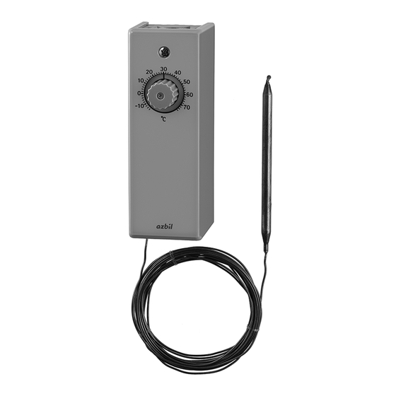
„ General
Models TY6800Z and TTY6800Z are insertion
thermostats applicable to control temperature (two-
position) for air in duct and liquid in tank or pipe.
„ Features
(1) Electric two-position control
The temperature sensing element, filled with
liquid, detects changing of temperature.
Model TY6800Z has a built-in microswitch,
TTY6800Z has two built-in microswitches. They
are applicable to heating or cooling control.
(2) Easy temperature setting and differential gap
adjustment
Temperature setpoint is easily set by the knob
in the front of the thermostat.
Model TY6800Z has the differential gap adjustment function to control equipment smoothly.
Each microswitch of Model TTY6800Z has the fixed differential gap. Difference between the two switches
is easily adjusted to enable suitable sequence control for the connected equipment.
„ Model Numbers
Model Number
TY6800Z6000
TY6800Z6010
TY6800Z7000
TY6800Z7010
TY6800Z8000
TY6800Z8010
TTY6800Z6000
TTY6800Z6010
TTY6800Z7000
Note: Actual length of capillary is 1.35–1.6 m for 1.5 m type, 4.75–5 m for 5 m type. Order the capillary considering the minimum required length.
z Parts ordered separately
Description
Immersion well
Pressure fitting
Temperature sensor holder
Insertion Thermostat
Temperature
Allowable max. temp.
setting range (°C)
of temp. sensor (°C)
-15–70
-15–70
5–90
5–90
40–125
40–125
-15–70
-15–70
5–90
Model Number
112624AA-J
R1/2 SUS304
83165370-001
1/2NPT
DY3002A1011
Construction
material
Allowable min. temp.
of temp. sensor (°C)
100
-40
100
-40
100
-40
100
-40
150
-40
150
-40
100
-40
100
-40
100
-40
Note
Figure 2. in this manual
AB-4074, Immersion Wells Specifications/
Instructions
Figure 3. in this manual
Figure 4. in this manual
AB-4009, Bulb Holder Specifications/
Instructions
1
AB-6600
Specifications/Instructions
Capillary length (m)
1.5
5
1.5
5
1.5
5
1.5
5
1.5
Reference
Advertisement
Table of Contents

Subscribe to Our Youtube Channel
Related Manuals for Azbil TY6800Z Series


Summary of Contents for Azbil TY6800Z Series
- Page 1 AB-6600 Specifications/Instructions Insertion Thermostat „ General Models TY6800Z and TTY6800Z are insertion thermostats applicable to control temperature (two- position) for air in duct and liquid in tank or pipe. „ Features (1) Electric two-position control The temperature sensing element, filled with liquid, detects changing of temperature.
-
Page 2: Safety Instructions
use. The symbol inside indicates the Azbil Corporation will not bear any responsibility for specific type of danger.(For example, the sign the results produced by the operators. on the left warns of the risk of electric shock.) - Page 3 AB-6600 CAUTION IMPORTANT • To use this product properly, follow the instructions described in this manual and U s e t h i s p r o d u c t u n d e r t h e o p e r a t i n g the manuals for other devices connected conditions (for temperature, humidity, to this product.
-
Page 4: Auxiliary Parts
AB-6600 z Auxiliary parts < Immersion well > R1/2 screw Seal ring Figure 2. Dimensions of Model 112624AA-J (mm) < Pressure fitting > Packing Washers (x4) Capillary tube 1/2NPT Figure 3. Dimensions of Model 83165370-001 (mm) < Temperature sensor holder > 17.5 (3.5) 22.4... - Page 5 AB-6600 „ Specifications Item Specification Differential Model Two-position control Approx. 3–11 °C (variable) TY6800Z Model Two-position, two-step Each microswitch's differential gap: fixed to approx. 3 °C TTY6800Z control Differential between two switches: approx. 2.5–8 °C (variable) Switching operation Refer to Figure 13., Figure 16., and „ Operation. Model When temperature rises, terminal R and W are Closed, terminal R and B are Open.
-
Page 6: Installation Procedure
AB-6600 „ Installation z Installation procedure CAUTION IMPORTANT • Do not twist or sharply bend the capillary U s e t h i s p r o d u c t u n d e r t h e o p e r a t i n g tube. - Page 7 AB-6600 (Wall or panel) 4.5 Hole Figure 7. Mounting wall/panel dimensions (mm) Wall plate t1.6 ~ 3.2 Main unit Mounting nuts (x3) Accessories: M4 Mounting screws (x3, accessories) M4, L=12 Figure 8. Installation procedure...
- Page 8 AB-6600 Knockout hole for wiring Before the installation, remove the knockout hole on the top or bottom surface of the case, which will be used to lead in the wires. The capillary tube can be taken out from the top of the main unit. Mount the main unit using the screws and nuts through the 3 mounting holes on the rear side of the case.
- Page 9 AB-6600 „ Wiring WARNING IMPORTANT • To use this product properly, follow the instructions described in this manual and If this product is connected to a system, be the manuals for other devices connected sure to implement safety measures. to this product. Failure to do might cause fire.
-
Page 10: Wiring Method
AB-6600 z Attaching the grommet (accessory part) z Wiring method It it is recommended using cable glands for wiring. If cable glands are not used, hold the wires near Tabs (on both sides) the product in order to reduce tension from the wires. - Page 11 AB-6600 z Model TTY6800Z z Model TY6800Z Switch 2 (left-hand) Switch 1 (right-hand) Temperature Temperature rise rise Temperature rise When temperature rises, terminal R and W are Closed, As temperature rises, switch 1 (right-hand) operates first, and terminal R and B are Open. then switch 2 (left-hand) operates.
- Page 12 AB-6600 • To wire between the microswitch and the screw terminals, lay the wires from the terminals to the microswitch though the bottom inside of the box. • Connect the wires to the screw terminals using the round screw terminals (M4 size) as shown in Figure 19. Note: If the wiring was done improperly, the terminal lugs or wires may interfere each other and the terminal cover cannot be attached.
- Page 13 AB-6600 „ Settings IMPORTANT • According to the thermal load, be careful to specify the differential gap so as not to cause huntings. Failure to do so might start and stop the devices frequently and cause device failure. • Specify the differential gap appropriately, not too wide. Failure to do so might cause contact failure.
- Page 14 AB-6600 „ Operations Set a desired temperature (refer to Settings) and power on the thermostat to run it automatically. z Model TY6800Z Between terminal R and W: Open Between terminal R and W: Close Between terminal R and B: Close Between terminal R and B: Open Differential gap Approx.
- Page 15 AB-6600 z Model TTY6800Z As shown in Figure 27. Setpoint and differential gap for Model TTY6800ZE, the differential gap of each switch is fixed to 3 °C. A dial for setting the setpoint is placed above the switch 1. Differential between two switches can be set approx.
-
Page 16: Operation Check
AB-6600 < Heating two-step control > Based on the heating control system shown in Figure 18. Example of wiring for heating two-step control, operation of Model TTY6800Z thermostat is described assuming the temperature setpoint: 50 °C, differential gap: 3 °C, differential between two switches: 8 °C. (1) When the temperature of the controlled target falls to 55 °C, that is setpoint (50 °C) plus the differential between two switches (8 °C) minus the differential gap (3 °C), the switch 2 works to close the terminal R2 and W2, and then the heater 1 starts. - Page 17 AB-6600 „ Maintenance WARNING If this product is connected to a system, be sure to implement safety measures. Failure to do might cause fire. Be sure to ground the product with ground resistance of less than 100 Ω. Improper grounding might ...
- Page 18 AB-6600 This blank page is added for page layout purposes.
- Page 19 AB-6600 This blank page is added for page layout purposes.
- Page 20 Specifications are subject to change without notice. Building Systems Company http://www.azbil.com/ Rev. 3.0 Aug. 2015 AB-6600 (J: AI-6600 Rev. 4.0)
Need help?
Do you have a question about the TY6800Z Series and is the answer not in the manual?
Questions and answers