
Related Manuals for Elvox 945F T


Summary of Contents for Elvox 945F T
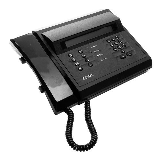
- Page 1 APARTMENT BLOCK SWITCHBOARD FOR 2 WIRE ELVOX SYSTEMS INSTALLATION AND OPERATION MANUAL Art. 945F Art. 945F/T Product is according to EC Directive 2004/108/CE, 2006/95/CE and following norms.
-
Page 2: Table Of Contents
1.2.6. Summary of main configuration commands SWITCHBOARD CONFIGURATION 2.1. HARDWARE CONFIGURATION 2.1.1. Switchboard ID configuration 2.1.2. Procedure for switchboard start-up in Elvox 2-wire systems 2.1.3. Switchboard keyboard lock 2.1.4. Access to programming mode with reset button 2.1.5. Night-time service 2.2. -
Page 3: General Information
INTRODUCTORY NOTES Type 945F enables the set-up of an alphanumeric switchboard for Elvox 2-wire video door entry systems. The device is configu- red as standard with an alphanumeric LCD display (2 rows x 40 columns) for the display of communication messages to and from... -
Page 4: Operator Interface
1.2. OPERATOR INTERFACE 1.2.1. Display The switchboard display is divided into four sections: each section can display specific information for the operator regarding swit- chboard operating and communication status. DATE/TIME MESSAGES TYPE 1 ICONS MESSAGES TYPE 2 Type 1 Messages: all messages of incoming calls from the riser or entrance panel are displayed or those of switchboard calls in progress;... -
Page 5: Keyboard Indicators
KEYBOARD DESCRIPTION Left-hand area SYMBOL KEY DESCRIPTION SCROLL MEMORIES Enables the user to consult calls or function activations from interphones or monitors connected to the riser. In programming mode, simulates an UP arrow of the programmer type 950C. LOCK OPEN Enables activation of switchboard terminal “SR”... -
Page 6: Pushbuttons And Adjustment Trimmers
1.2.4 Push-buttons and adjustment trimmer Matricola / Ref. N. Art. 945F Art. 945F/T Made in Italy 1.2.5. Switchboard handset The switchboard communicates with the rest of the system (panel or internal device) via the handset at the left side of the unit. This switchboard is not fitted with a mechanical hook;... -
Page 7: Switchboard Configuration
Procedure for switchboard start-up in Elvox 2-wire systems In each two wire Elvox system there can only be one MASTER or main panel at a time. The main entrance panel is also the only panel that on reset or power-up queries the other system panels to detect the type and presence of each. The system must not be used during this phase. -
Page 8: Switchboard Keyboard Lock
1) disconnect the power supply to the switchboard and then reconnect, for example by reinserting the plug in the connection boss. 2) wait for the text *** Elvox 2-Wire System *** to appear on display and then immediately press keys simul- taneously for a few seconds. - Page 9 1 = English Local language Language of the messages shown on the switchboard display. Switchboard ID In Elvox 2-wire systems, up to a maxi- mum of four switchboards can be used with ID from 1 to 4. Code digits # Natural...
-
Page 10: Message Language
2.2.2. MESSAGE LANGUAGE Programming can be in Italian (default local language) or English Other local languages will be available for the respective markets To change language, press for Italian or for English To cancel press . To confirm, press Acceptance of the command, as in all cases, is shown on the first line of the display: The display now changes to: Use the key to move to the previous item in the programming menu. -
Page 11: Device Numbering
2.2.5. Device numbering If number encoding is programmed for 4 or 8 digits, i.e. when sequential encoding is not selected, press the key to move to the next item to enable modification of the correspondence between ID of each monitor or interphone with the numbering used to call from the switchboard keyboard. -
Page 12: Search The Entire Agenda
And lastly: 2.2.6. Search the entire agenda Press to move to the next item in which the switchboard can be configured to scroll through the entire agenda on entry of a blank name as the search criteria. Normally at least the first letter of the name to be searched should be entered. With the flag selected, press followed by to see the first name in the agenda, regardless of the initial. - Page 13 BUTTON SYMBOL <spazio>1@.,:;?!()<> ABC2abcÁÀÃÅÄÆÇÈáàãåäæçè DEF3defïÉÈÊÌéèêì GHI4ghiÍÌíì JKL5jkl MNO6mnoÑñÓÒÕÖóòõö PQRS7pqrsRŠršß PQRS TUV8tuvÚÙÜÙúùüù WXYZ9wxyzÝZýz WXYZ 0_$&*#+-=/%"' If the symbol entered previously was a capital letter, even if the push-button is changed, the system re-starts with a capital. If it was lower case, you will re-start in lower case. If it was a digit, you will re-start with a digit. If the next symbol to enter is on another key, there is no need to wait for the timeout to elapse before proceeding.
-
Page 14: Programming Password
When the user exits this menu and a modification has been made to any of the names, the name indexing procedure is started in the background (i.e. without stopping panel activities) so that the search to make a call is performed in strict alphabetical order, on the basis of the initial letters entered by the user according to the procedure described in the panel instructions. -
Page 15: Function 1 Time
To cancel press . To confirm, press . Acceptance of the command, as in all cases, is shown on the first line of the display: If the time is outside the admissible interval, i.e. over 255 seconds, the first line of the display shows the error: Use the key to move to the previous item in the programming menu. -
Page 16: Common F1
To cancel press . To confirm, press . Acceptance of the command, as in all cases, is shown on the first line of the display: If the ID is outside the admissible range, the first line of the display shows the error: To cancel the assignment, enter a single ‘0’... -
Page 17: Keyboard Beep
2.2.16. Keyboard beep Press to move to the next item in which the key press check tone on the panel can be activated (default) or deactivated The current value is shown on display: Press to activate the tone, or to disable To cancel press . -
Page 18: On External Mode
2.2.18.2 On external mode By pressing push-button you can go to the following function through which you can activate or deactivate (default) the call filter from the monitors / interphones to the switchboard on external mode. The message displayed corresponds to the current value: By pressing push-button the filter is deactivated, by pressing the filter is activated. -
Page 19: Clock
Programming is by means of low level messages sent to the bus of the Elvox 2-wire system, querying individual monitors/interphones, referred to below in general as “Devices”. - Page 20 P A R A M E T E R S F O R P R O G R A M M I N G CLASS MEANING 6209 (+ 6009) 6309 YES = the monitor switches on when a panel call is made (except for 6209) YES = the green led is managed as door open indicator YES = the lock pushbutton is used by the device...
- Page 21 P A R A M E T E R S F O R P R O G R A M M I N G CLASS MEANING 6209 (+ 6009) 6309 P0 is lock push-button Functions assigned to pushbuttons. P1, P2, P3, P7 and P8 as default (i.e.
- Page 22 P A R A M E T E R S F O R P R O G R A M M I N G CLASS MEANING 6601 6611 8879 YES = the monitor switches on when a panel call is made (not for 6601AU or 6611AU) YES = the green led is managed as door open indicator YES = if the F1 / F2 pushbutton is programmed...
- Page 23 P A R A M E T E R S F O R P R O G R A M M I N G A N D H A R D W A R E 8879 MEANING CLASS 6601 6611 Functions assigned to pushbuttons.
-
Page 24: Monitor/Interphone Configuration Modification
2.3.1. Flag programming To modify one of the flag settings (YES / NO) use key for NO and for YES. To confirm, press . For example, press on the item “green LED ” to display the confirmation Use the key to skip all intermediate phases and go to the next group;... -
Page 25: Intercommunicating Call Ringtone Mute
To cancel press . To confirm, press the display changes as follows, to indicate the specific self-start function: 2.3.2.4. Auxiliary Enter the ID of an auxiliary from 1 to 16: To cancel press . To confirm, press the display changes as follows, to specify activation of an auxiliary: Note that auxiliaries 1-2 correspond to the first and second relay of the first actuator. -
Page 26: Door Lock Push-Button
2.3.2.11 DOOR LOCK PUSH-BUTTON It is also possible to re-configurate the door lock push-button. As default it activates the lock release of the entrance panel with that is talking or, with hook pressed, with the latest panel it got in touch with. Raising the hook, starting from a rest position and by pressing the lock release push-button, you make a call to an existing lodge switchboard. -
Page 27: Ringtone Volume
2.3.4.3. Ringtone type This is the volume of the ringtone, for panel calls. To change, press a key from 0 to 6: To cancel press . To confirm, press . The display changes as follows: 2.3.4.4. Brightness (not versions AU) This is the level of monitor brightness 66x1 and 67x1. - Page 28 2.3.5. CONFIGURATION OF REMOTE BUTTON MODULE Press to move to the next item by which you can program 8 Button Modules Type 6120. At the outermost part of this function you move by pressing to select the required Module. The type of Button Module and the respective firmware version are shown on the second line.
-
Page 29: Contrast (Not Versions Au)
OPERATING MODES This chapter describes the operations which must be made with the switchboard to communicate with a panel or internal device, or enable intercommunicating calls between two internal devices. As described above (see paragraph 2.1.2) the switchboard can operate in two separate ways: external and internal mode. 3.1. -
Page 30: Call From Switchboard To Internal Device
alternating with: - make the call to the internal device requested by pressing . The following text is displayed: alternating with: - if the internal device consents, the switchboard operator uses the key to connect the caller panel to the internal device, and the switchboard display shows confirmation of communication in progress with: At the same time, the green INTERC led illuminates to indicate audio communication active between the panel and inter-... -
Page 31: Intercommunicating Call Between Two Internal Devices
Audio communication between the switchboard and internal recipient is indicated by the message type: The switchboard envisages three types of numerical selection associated with an internal device: - natural encoding: in this case the number to dial coincides with the HW ID of the internal device (monitor/interphone) to be cal- led;... -
Page 32: Mode During Communication With A Panel
At any activation a respective icon appears above on the right hand side of display. Through push-buttons it is possible to select the increasing or decreasing number of panel on which to effect the operations forseen with the numerical push-buttons shown on the second line of display: By pressing the push-button you can return to the switchboard rest initial state. - Page 33 a unique event is proposed a the current date and time. This can be modified by moving through the fields using keys . Once in the selected field, highlighted by the symbol , use keys for the numerical fields. For the month field, enter the number 01 for January, through to 12 for December. For fields requiring a weekday, use the keys according to the following scheme: Sunday Monday...
-
Page 34: Internal Appointments
When the switchboard is in the rest status, the system checks whether the time of the first active appointment has elapsed accor- ding to the natural sequence. The check is performed every minute but is not synchronized with the clock. If the time has elapsed, the switchboard speaker emits three beeps at a frequency of approx. -
Page 35: Event Management
To confirm the appointment, press . If all is correct, the new selections are saved; otherwise the error message is displa- and the inconsistency is shown by the symbol To change the type of repetition use key while in appointment editing mode. The configuration changes according to the previous situation and position. -
Page 36: List Viewing
Connection stud The switchboard receives power and is integrated (switchboard-riser) in any Elvox 2-wire system by means of an exter- nal terminal block called BOSS. This comprises The stud consists of: two rows of terminals to which all signals required... - Page 37 Name terminal boss Mark Colour of corresponding wire Switchboard signal (corresponding terminal analogue number) Coaxial cable (internal wire) Video signal from camera Coaxial cable (sheath) Video ground from camera Grey-Green White-Violet Blue Lock output (open collector) White-grey Ground White-Orange F2 output (open collector) Grey_Violet F1 output (open collector) White-Black...
-
Page 38: Monitor Boss For Switchboard 945F
4.2. MONITOR BOSS FOR SWITCHBOARD 945F The monitor 6009 with desktop base 6A92 is fitted with a cable with one end equipped with a plug for connection to a boss with the following connections. External connections are also specified between the two bosses to ensure correct system operation. Mark Colour of corre- Terminal... -
Page 39: Correspondence Of Keys On Switchboard And Remote Telephone
NOTE: THE TELEPHONE RINGS ONLY IF THE SWITCHBOARD IS SET TO NIGHT-TIME SERVICE, BUT CAN DIAL AND THE HOOK IS ALWAYS ENABLED. 5.2. CORRESPONDENCE OF KEYS ON SWITCHBOARD AND REMOTE TELEPHONE The corresponding keys between the switchboard and telephone keypad are shown in the following table SYMBOL KEY TELEPHONE KEYS .. -
Page 40: Connections To Boss
5.4. CONNECTIONS TO BOSS The 6-way terminal located to the lower left in CS2741, is connected by means of 6 wires to the switchboard boss: Mark 945F boss terminal terminal block (Number / name) 21 / A 22 / M 23 / TO 24 / TI 25 / RX... - Page 41 SIMPLE AUDIO ENTRANCE PANEL SYSTEM WITH APARTMENT BLOCK SWITCHBOARD TYPE 945F (N° SI226) Cable riser Phone Cable Art. 6601/AU Art. 732H Art. 660C/AU Art. 732I Art. 6711/AU Art. 6611/AU Art. 661C/AU Art. 6711/AU Cable Art. 732H Art. 732I Phone Art. 8879 Cable Art.
- Page 42 SIMPLE VIDEO ENTRANCE PANEL SYSTEM WITH APARTMENT BLOCK SWITCHBOARD TYPE 945F (N° SI227) Cable riser Monitor Cable Art. 6611 Art. 732H Art. 661C Art. 732I Art. 6711 Art. 6621 Art. 662C Art. 6721 Cable Art. 732H Art. 732I Monitor Art. 6329 Art.
- Page 43 VARIATION ON THE CONNECTION OF THE APARTMENT BLOCK SWITCHBOARD TYPE 945F WITH MONITOR TYPE 6009 - 6009/C BY MEANS OF THE TABLE-TOP CONVERSION KIT TYPE 6A92 (N° SI228). Attention: Cable riser In the connection stub respect attentively the connections. The inversions in cablings may damage the switchboard and/or the Mains moniteur.
- Page 44 VARIATION ON THE CONNECTION OF THE APARTMENT BLOCK SWITCHBOARD TYPE 945F – 945F/T WITH MONITOR TYPE 6009 - 6009/C BY MEANS OF THE TABLE-TOP CONVERSION KIT TYPE 6A92 AND LODGE CAMERA CCTV TYPE (N° SI229). Attention: In the connection stub respect attentively the connections.
- Page 45 VARIATION ON THE CONNECTION OF THE APARTMENT BLOCK SWITCHBOARD TYPE 945F – 945F/T WITH TWO RELAYS TYPE 170/001 FOR THE ACTIVATION OF TWO AUXILIARY FUNCTIONS “F1 – F2” (N° SI230). Cable riser Relais Relais Power supply Mains Art. 0170/001 Art. 0170/001 Art.
- Page 46 VARIATION ON THE CONNECTION OF THE APARTMENT BLOCK SWITCHBOARD TYPE 945F – 945F/T WITH ONE RELAY TYPE 170/001 AND TRANSFORMER TYPE 832/030 FOR THE ELECTRIC LOCK CONTROL (N° SI231). Transformer Art. 0832/030 Cable riser Relay Power supply Art. 0170/001 Art. 6923 Cable Art.
- Page 47 The instruction manual is downloadable from the site www.vimar.com Installation rules Installation should be carried out by qualified personnel in compliance with the current regulations regarding the installation of electrical equipment in the country where the products are installed. Conformity EMC directive Standards EN 61000-6-1 and EN 61000-6-3.
- Page 48 Viale Vicenza, 14 36063 Marostica VI - Italy www.vimar.com S6I. 1910...
Need help?
Do you have a question about the 945F T and is the answer not in the manual?
Questions and answers