
Related Manuals for CooperSurgical RI INTEGRA 3


Summary of Contents for CooperSurgical RI INTEGRA 3
- Page 1 User Manual RESEARCH INSTRUMENTS LTD Bickland Industrial Park, Falmouth, Cornwall, TR11 4TA, UK 0120 Tel: +45 4679 0202 | Email: customerservice@origio.com | origio.com Document 6-54-701UM, Issue 9, DRF 4525, 19 September 2018...
-
Page 2: Table Of Contents
CONTENTS SECTION 6 - ELECTRONIC CONTROL SYSTEM Display SECTION 1 - PREFACE User Interface Icons Shortcut Buttons SECTION 2 - INTRODUCTION TO THE INTEGRA 3 Stopwatch Counter Intended Use Under-stage Lights Applicable Part Numbers Height Indicators Microscope Compatibility Height Indicator Calibration Installation System Information SECTION 3 - SAFETY WARNINGS... - Page 3 Section 1 Research Instruments Ltd Preface SOS - Screw-Actuated Oil Syringe Overview SOS Specification Table SECTION 1 - PREFACE Fitting Tubing to a SOS Filling a SOS with Oil Thank you for choosing the Integra 3. Fitting a Pipette Using a SOS This manual provides all necessary information to use the Research Instruments Integra 3 micromanipulation system.
-
Page 4: Section 2 - Introduction To The Integra 3
Section 2 Section 2 Introduction to the Integra 3™ Research Instruments Ltd Research Instruments Ltd Introduction to the Integra 3™ SECTION 2 - INTRODUCTION TO THE INTEGRA 3 Applicable Part Numbers Part Number Description Intended Use 6-54-110 Integra 3 with Heated Metal Insert To precisely position microtools under a microscope whilst maintaining 6-54-100 Integra 3with Heated Metal Insert and Thermosafe... -
Page 5: Section 3 - Safety Warnings
Section 3 Section 3 Integra 3™ Safety Warnings Research Instruments Ltd Research Instruments Ltd Integra 3™ Safety Warnings SECTION 3 - SAFETY WARNINGS Guidance & Manufacturer’s Declaration - Electromagnetic Emissions (IEC 60601-1-2) The Integra 3 is intended for use in the electromagnetic environment DO NOT disassemble or modify any part of the Integra 3, or specified below. - Page 6 Section 3 Section 3 Integra 3™ Safety Warnings Research Instruments Ltd Research Instruments Ltd Integra 3™ Safety Warnings Guidance and Manufacturer’s Declaration - Electromagnetic Immunity IMMUNITY IEC 60601 Compliance Electro magnetic Test Test level level environment - guidance This equipment is deigned to be used by professionals in a laboratory environment Portable and mobile RF and conforms to IEC 60601-1-2 electromagnetic compatibility for professional use, communications equipment...
-
Page 7: Glossary Of Safety/Information Symbols
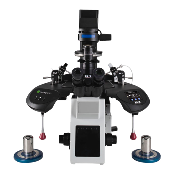
Section 3 Section 4 Integra 3™ Safety Warnings Research Instruments Ltd Research Instruments Ltd Integra 3™ Product Overview Glossary of Safety/Information Symbols SECTION 4 - PRODUCT OVERVIEW Source: ISO 15223-1:2016 BS EN 60601-1:2006 + A12:2014 Welcome to the user manual for the Research Instruments Integra 3 Symbol Meaning micromanipulation workstation. -
Page 8: System Components
Section 4 Section 4 Integra 3™ Product Overview Research Instruments Ltd Research Instruments Ltd Integra 3™ Product Overview System Components The following tables give part numbers of system components and microscope adaptors. All parts are supplied or manufactured by Research Instruments Ltd. -
Page 9: Integra 3 System Microscope Adaptor Part Numbers
Section 4 Section 4 Integra 3™ Product Overview Research Instruments Ltd Research Instruments Ltd Integra 3™ Product Overview Integra 3 System Microscope Adaptor Part Numbers Hardware Overview Micropipette Note: The front and rear adaptors are specified according to microscope. Holder (MPH) Part numbers given below include the front adaptor, rear adaptor and Heated Stage PL3 Toolholder... -
Page 10: Device Label
Section 4 Section 4 Integra 3™ Product Overview Research Instruments Ltd Research Instruments Ltd Integra 3™ Product Overview Device Label Integra 3 Specification Table Part Description X, Y and Z movement from one lever Manipulator (X = side to side, Y = front to back, Z = up and down) Fine Control Sub-micron resolution 0.75mm X and Y travel, 5mm Z travel... -
Page 11: Section 5 - Basic Operation
Section 5 Section 5 Integra 3™ Basic Operation Research Instruments Ltd Research Instruments Ltd Integra 3™ Basic Operation The Coarse Control Lever moves the end of the micropipette through a SECTION 5 - BASIC OPERATION maximum of 4mm in the x-y plane for coarse positioning of the pipette. The Fine Control Lever moves the pipette through a maximum of 0.75mm Coarse Control Lever Left in the x and y planes, and is used for accurate positioning of tools and... -
Page 12: Heated Stage Plate
Section 5 Section 5 Integra 3™ Basic Operation Research Instruments Ltd Research Instruments Ltd Integra 3™ Basic Operation The RI Droplet Organisation Guide (Part Number 6-30-600) can be used The Heated Glass Insert is fragile and should be handled with to position droplets within commonly used Petri dishes in order to ensure care. -
Page 13: Fitting Micropipettes
Section 5 Section 5 Integra 3™ Basic Operation Research Instruments Ltd Research Instruments Ltd Integra 3™ Basic Operation Fitting Micropipettes Inserting MPH into Toolholder The Integra 3 is designed to use industry standard 1.0mm diameter glass Raise the Set-up Lever located on the side of the toolholder and rotate micropipettes, such as RI’s ICSI Plus range. - Page 14 Section 5 Section 5 Integra 3™ Basic Operation Research Instruments Ltd Research Instruments Ltd Integra 3™ Basic Operation 2. Take an empty and clean Petri dish (set-up dish), and lightly scratch a 9. Turn the Raised Position Adjustment Screw on each side, not the cross in its centre, on the upper surface.
-
Page 15: Pipette Angle Adjustment
Section 5 Section 5 Integra 3™ Basic Operation Research Instruments Ltd Research Instruments Ltd Integra 3™ Basic Operation Pipette Angle Adjustment 11. Refit the PL3 and set the Raised Position Adjustment Screw at the centre of the range of movement using the PL3 Set-up Tool (or Turn the Pipette Angle Control to increase or decrease the angle of the measure a height of 14mm). -
Page 16: Shut Down Procedure
Section 5 Section 6 Integra 3™ Basic Operation Research Instruments Ltd Research Instruments Ltd Integra 3™ Electronic Control System 1. Move the Fine (red) and Coarse (blue striped) Levers to a vertical SECTION 6 - ELECTRONIC CONTROL SYSTEM position. Rotate the Fine Control Lever to the centre of the movement Display as indicated on the display. -
Page 17: User Interface Icons
Section 6 Section 6 Integra 3™ Electronic Control System Research Instruments Ltd Research Instruments Ltd Integra 3™ Electronic Control System User Interface Icons The following table explains the meaning of all the user interface icons Please refer to the User Interface Icons table on the previous page for required to use and adjust the Integra 3 settings and features. -
Page 18: Height Indicators
Section 6 Section 6 Integra 3™ Electronic Control System Research Instruments Ltd Research Instruments Ltd Integra 3™ Electronic Control System Height Indicators These show the vertical position of the toolholders, as set by rotating the Fine Control Levers. If the Fine Control is turned close to the ends of the range of movement, the display will turn red and the Integra 3 will emit three short beeps, repeating every 5 seconds. -
Page 19: Section 7 - Temperature Control
Section 7 Section 7 Integra 3™ Temperature Control Research Instruments Ltd Research Instruments Ltd Integra 3™ Temperature Control SECTION 7 - TEMPERATURE CONTROL Heated Stage Plate Only (Modes 4 and 5) The Integra 3 can be configured to operate only the Heated Stage Plate. To ensure embryo safety, the temperature setpoint should This is typically only required when using the Integra 3 with an externally be set to maintain the specimen at the correct temperature. -
Page 20: Setting The Temperature
Section 7 Section 7 Integra 3™ Temperature Control Research Instruments Ltd Research Instruments Ltd Integra 3™ Temperature Control Setting the Temperature Where the Thermosafe Air Heating System is fitted, it is recommended that temperature measurements are made above the centre of the objective and over the heated plate (see Figure 7-1 on page 35). -
Page 21: Calibrating Heated Plates
Section 7 Section 7 Integra 3™ Temperature Control Research Instruments Ltd Research Instruments Ltd Integra 3™ Temperature Control Temperature calibration can be performed on each of the heating options Note: For the Heated Glass Insert, it is not recommended that listed at the start of the Temperature Control section. -
Page 22: Section 8 - Alarms And System Status
Section 8 Section 8 Integra 3™ Alarms and System Status Research Instruments Ltd Research Instruments Ltd Integra 3™ Alarm and System Status SECTION 8 - ALARMS AND SYSTEM STATUS Priority Range Average The status of the temperature control system is shown by the Status Medium Priority 54.3 - 65.1dB 63.4dB(A) -
Page 23: Section 9 - Syringes
Section 9 Section 9 Syringes Research Instruments Ltd Research Instruments Ltd Syringes SECTION 9 - SYRINGES SAS - Screw-Actuated Air Syringe Assembly Note: Do not fill the syringe or tubing with oil Safety Spigot High pressure can be generated in the system when using small diameter micropipettes, viscous fluids, or if a micropipette becomes blocked. -
Page 24: Sas Operation
Section 9 Section 9 Syringes Research Instruments Ltd Research Instruments Ltd Syringes SAS Operation Equilibration Procedure Suction/Injection is obtained by turning the rotator on top of the syringe. This procedure balances the pressure in the syringe with the capillary action of the pipette, allowing the most accurate control of the sperm injection. -
Page 25: Sos - Screw-Actuated Oil Syringe Overview
Section 9 Section 9 Syringes Research Instruments Ltd Research Instruments Ltd Syringes SOS - Screw-Actuated Oil Syringe Overview Fitting Tubing to a SOS Use hard polythene tubing as supplied by RI. Use of soft tubing will The SOS is a screw actuated syringe for the precise transfer and injection result in poor specimen control. -
Page 26: Filling A Sos With Oil
Section 9 Section 9 Syringes Research Instruments Ltd Research Instruments Ltd Syringes Filling a SOS with Oil 4. Turn the SOS to a horizontal position. Add a few drops of oil to the fill port until the oil is level with the top of the port. RI recommends sterile filtered paraffin oil. -
Page 27: Fitting A Pipette
Section 9 Section 9 Syringes Research Instruments Ltd Research Instruments Ltd Syringes 7. Stand the SOS on end as shown below. Turn the Control knob to Fitting a Pipette move the plunger below the fill port. Remove the cap from the fill port. -
Page 28: Section 10 - Troubleshooting
Section 10 Section 10 Integra 3™ Troubleshooting Research Instruments Ltd Research Instruments Ltd Integra 3™ Troubleshooting SECTION 10 - TROUBLESHOOTING For any issues not covered below, please contact your distributor or the Problem Possible Cause Solution RI service team directly (see page 71 for RI contact details). Manipulation Objectives are focused Refocus on the top surface of a Petri dish... -
Page 29: Alarm Code Tables
Section 10 Section 10 Integra 3™ Troubleshooting Research Instruments Ltd Research Instruments Ltd Integra 3™ Troubleshooting Alarm Code Tables Alarm Fault Alarm Condition Message Priority Description/ Solution Actions Code Alarm Criteria The following tables on pages 52 to 62 lists Alarm Condition Code Heated Stage Insert numbers, displayed Error Message, Priority, Fault Description, Alarm is not able to heat. - Page 30 Section 10 Section 10 Integra 3™ Troubleshooting Research Instruments Ltd Research Instruments Ltd Integra 3™ Troubleshooting Alarm Fault Alarm Fault Alarm Alarm Condition Message Priority Description/ Solution Condition Message Priority Description/ Solution Actions Actions Code Alarm Criteria Code Alarm Criteria Switch off the Temperature No signal/out of...
- Page 31 Section 10 Section 10 Integra 3™ Troubleshooting Research Instruments Ltd Research Instruments Ltd Integra 3™ Troubleshooting Alarm Fault Alarm Fault Alarm Alarm Condition Message Priority Description/ Solution Condition Message Priority Description/ Solution Actions Actions Code Alarm Criteria Code Alarm Criteria Thermosafe Heated Switch off the...
- Page 32 Section 10 Section 10 Integra 3™ Troubleshooting Research Instruments Ltd Research Instruments Ltd Integra 3™ Troubleshooting Alarm Fault Alarm Fault Alarm Alarm Condition Message Priority Description/ Solution Condition Message Priority Description/ Solution Actions Actions Code Alarm Criteria Code Alarm Criteria This may be caused by placing either...
- Page 33 Section 10 Section 10 Integra 3™ Troubleshooting Research Instruments Ltd Research Instruments Ltd Integra 3™ Troubleshooting Alarm Fault Alarm Fault Alarm Alarm Condition Message Priority Description/ Solution Condition Message Priority Description/ Solution Actions Actions Code Alarm Criteria Code Alarm Criteria Switch off the Switch off the Integra 3...
- Page 34 Section 10 Section 10 Integra 3™ Troubleshooting Research Instruments Ltd Research Instruments Ltd Integra 3™ Troubleshooting ITO Heated After power ITO Heated Glass Glass Insert is switched Insert has come controller The microscope off and then into electrical power is set objective must on all heating contact with...
-
Page 35: Section 11 - Care And Maintenance
Section 10 Section 11 Integra 3™ Care and Maintenance Integra 3™ Troubleshooting Research Instruments Ltd Research Instruments Ltd SECTION 11 - CARE AND MAINTENANCE Problem Possible cause Solution Regular servicing by an RI authorised technician will help to ensure Tip of the that your system performs at its best. -
Page 36: Replacing The Micropipette Holder Tip O-Ring
Section 11 Section 11 Integra 3™ Care and Maintenance Integra 3™ Care and Maintenance Research Instruments Ltd Research Instruments Ltd Replacing the Micropipette Holder Tip O-ring Thermosafe Air Heating System After a period of use the rubber O-ring inside the Micropipette Holder The Thermosafe Air Heating System contains a filter which can be easily (MPH) will become worn and will allow air leaks to affect the injection/ replaced by the user. -
Page 37: Air Syringes - Inserting A New O-Ring
Section 11 Section 11 Integra 3™ Care and Maintenance Integra 3™ Care and Maintenance Research Instruments Ltd Research Instruments Ltd Air Syringes - Inserting a New O-ring Cleaning Use a dust cover to protect the Integra 3 when not in use. This will minimise the need for cleaning. -
Page 38: Section 12 - Repairs And Returns Procedures
Section 12 Section 12 Repairs and Returns Procedure Research Instruments Ltd Research Instruments Ltd Repairs and Returns SECTION 12 - REPAIRS AND RETURNS PROCEDURES Contact Details Reuse Statement Research Instruments Ltd, Bickland Industrial Park, Assuming your Integra 3 is regularly maintained and routinely serviced, Falmouth, Cornwall, TR11 4TA, UK it should perform as required for a minimum of 7 years continual use, Tel: +44 (0) 1326 372 753 Fax: +44 (0) 1326 378 783...
Need help?
Do you have a question about the RI INTEGRA 3 and is the answer not in the manual?
Questions and answers