Table of Contents
Advertisement
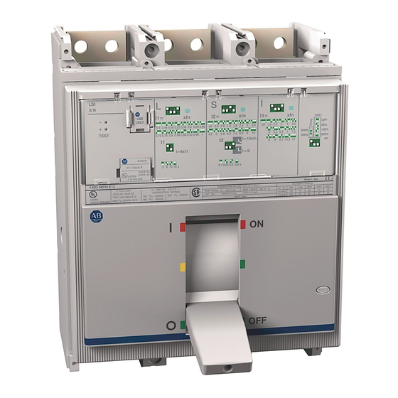
DIR 1000587R002 Version 02 140G-NTI-E12; 140G-NTK-E12; 140G-RTI-E30; 140G-RTK-E30
LSIG and LSIG-MM trip unit for 140G-N/ 140G-NS/ 140G-R
Installation - Installazione - Instalación
Instalação -
WARNING:
To prevent electrical shock, disconnect from power source before
installing or servicing. Install in suitable enclosure. Keep free from contaminants.
(Follow NFPA70E requirements).
AVVERTENZA:
Per prevenire infortuni, togliere tensione prima dell'installazione o
manutenzione. Installare in custodia idonea. Tenere lontano da contaminanti.
WARNUNG:
Vor Installations- oder Servicearbeiten Stromversorgung zur
Vermeidung von elektrischen Unfällen trennen. Die Geräte müssen in einem
passenden Gehäuse eingebaut und gegen Verschmutzung geschützt werden.
AVERTISSEMENT:
Avant le montage et la mise en service, couper l'alimentation
secteur pour éviter toute décharge. Prévoir une mise en coffret ou armoire appropriée.
Protéger le produit contre les environnements agressifs.
ADVERTENCIA:
Desconéctese de la corriente eléctrica, antes de la instalación o
del servicio, a fin de impedir sacudidas eléctricas. Instálelo en una caja apropiada.
Manténgalo libre de contaminantes.
ATENÇÃO: Para evitar choques, desconectar da corrente elétrica antes de fazer a
instalação ou a manutenção. Instalar em caixa apropriada. Manter livre de
contaminantes.
DIR 1000587R0002 (Version 02)
-
(1)
Bul. 140G/140MG
Advertisement
Table of Contents
Troubleshooting

Related Manuals for Allen-Bradley LSIG


Summary of Contents for Allen-Bradley LSIG
- Page 1 Bul. 140G/140MG DIR 1000587R002 Version 02 140G-NTI-E12; 140G-NTK-E12; 140G-RTI-E30; 140G-RTK-E30 LSIG and LSIG-MM trip unit for 140G-N/ 140G-NS/ 140G-R Installation - Installazione - Instalación Instalação - WARNING: To prevent electrical shock, disconnect from power source before installing or servicing. Install in suitable enclosure. Keep free from contaminants.
-
Page 2: Table Of Contents
Neutral Protection ....24 LSIG Trip Unit ..... . 4 3.6.10. -
Page 3: Lsig And Lsig-Mm Trip Units Functional Comparison
LSIG and LSIG-MM Trip Units Functional Comparison Function/Unit LSIG LSIG-MM Current protections (L, S, I, G) Additional protections (U, OT, MM) Thermal memory Maintenance mode Battery unit Key: : standard function/unit, O : optional function/unit, : function/unit unavailable. 1.1. Compatibility between trip units and CB... -
Page 4: Lsig Trip Unit
Battery Unit Catalog No:140G-ELBU [purchased separately] 2.2. Main specifi cations LSIG is an electronic device for AB 140G-N/140 G-NS/140G-R range of three-pole and four-pole Molded Case circuit breakers with functions for monitoring and for protecting against abnormal currents. The trip unit installed on the circuit-breaker is connected to the current sensors for primary current reading, and to the Trip Coil for the circuit-breaker opening command. -
Page 5: Compatibility Cb
2.2.4. Compatibility CB LSIG can be installed in AB circuit-breakers of the three-pole, three-pole with external neutral or four-pole type from the 140G-R, 140G-N and 140G-NS (any size). The CB model establishes the rated uninterrupted current the circuit-breaker is able to support (lu). -
Page 6: User Interface
2.3.1. Dip switches The dip switches on the front of LSIG are used for adjusting the tripping thresholds of each protection and the tripping time. The available combinations are given alongside each group of dip switches. The dip switches for regulating the tripping times of protections S (t2) and G (t4) can also be used for selecting the tripping curve: Fixed time tripping curve. -
Page 7: Led
Consult the chapters dedicated to the accessory modules for further details. 2.4. Protection functions LSIG handles up to 5 independent protection functions. The current signal from the current sensors is processed by the trip unit which, depending on the protection parameter settings, indicates alarms, performs delay processes and sends commands. -
Page 8: Protection L
= protection G parameters set by the user, given in [In] and [s] LSIG is able to provide Ground (Earth) fault protection, by vectorally adding together the phase and neutral currents. The fault current is defi ned by the following formula: If there is no fault in the circuit, I = 0. -
Page 9: Neutral Protection
2.4.5. Neutral Protection LSIG allows the current signal of the neutral pole to be processed with different ratios in relation to the phase values. The follow- ing values can be set for this protection: I N =Off - 50% - 100% - 200% * I . -
Page 10: Trip Curves
2.4.8. Trip curves The trip curves provided are merely for guidance and only show a sub-group of the possible selections. 2.4.8.1. Trip curves for functions L-S(t =k/I 2.4.8.2. Trip curves for functions L-S(t=k)-I t = k DIR 1000587R0002 (Version 02) (10) -
Page 11: Trip Curves For Function G
± 1.5 2.5.2. Self-monitoring LSIG provides certain self-testing functions to facilitate failure analysis in the case of faulty operation or incorrect confi guration of dip-switches and settings. Faults are signalled by a combination of led lights. The functions are as follows: ... -
Page 12: Putting Into Service And Recommendations
CS and TC connection check ATTENTION: If the LSIG has been installed by the user, remember to check (with the CB open and Vaux or battery unit), prior to putting the circuit-breaker into service, to make sure that the CS and TC cables have been con- nected correctly. -
Page 13: Troubleshooting
2.8.2. In the case of a fault ATTENTION: If the LSIG is suspected of being faulty, if there are signs of malfunctions or it has generated an unexpected trip, we advise you to strictly follow the recommendations below: 1. Press the “i Test” button (within 48 hours of CB opening or within 24 hours if the operating temperature is in the -40°..-25°... -
Page 14: Lsig-Mm Trip Unit
Instantaneous short-circuit (maintenance mode) In addition, LSIG-MM provides fi xed protection against instantaneous short-circuits at high currents, known as Iinst. 3.3.2. Functions LSIG-MM includes various different functions: - Runtime measurement of the main electrical quantities available: phase current, peak factor;... -
Page 15: Inputs/Outputs
ATTENTION: Separate DC power source must be galvanically separated from ground, in accordance with UL 60950 (IEC 60950) or equivalent IEC 60364-41 [CEI 64-8]. If supplied by primary current or voltage, LSIG-MM includes 3 different operating modes, depending on the level of the supply signals: - Low Power: this mode guarantees operation of all the protections provided by the tip unit, operation of the front LEDs and display energizing in the Low Power mode, but access to the menus is not allowed. -
Page 16: User Interface
3.4. User interface A graphic display and a push-button panel provide all the available settings and information. Ref. Description Serial number of the trip unit State LED Test connector Graphic display Main push-button panel Rating plug “i Test” button 3.4.1. LEDs The 2 front LEDs provide information about the state of the trip unit and CB. -
Page 17: Push-Buttons
3.4.3. Display LSIG-MM are equipped with a 128x64 pixel graphic LCD display where the operator can view measurements and signals, and access the menus with all the settings. The degree of contrast of the menu display can be adjusted by selecting the Settings menu and Display Contrast parameter. -
Page 18: Graphic Ammeter
Ref. Description Phase current measurement CB and/or trip unit alarms (sinewave logo appears in the absence of alarms) Internal clock “Low Power“ message Operating icons Graphic ammeter and voltmeter Rms value and highest measured current phase (cyclically updated value) Name of the menu being browsed List of options available in the menu being browsed (the value that appears in black is the one that has been selected) Number of options available in the menu being browsed Value or description of the selected option... -
Page 19: Operating Icons
3.5. User menus LSIG-MM come on in the Full Power mode in the presence of the supply conditions described in sect. 3.3.8 or if supplied by one of the following: Separate power supply or Battery unit. -
Page 20: Menu Area
3.5.2. Menu Area The menu area features a tree structure allowing all the information and parameters to be managed with various levels of detail. The main menu, which the user can access by pressing ESC from the default page, includes 5 options: Main Menu Option Description Paragraph... -
Page 21: Protection Functions
3.6.1. Notes about Protection Operation LSIG-MM is equipped with “backup-protection”. If the fi rst command to the trip coil fails to open the circuit-breaker immediately (TC locked), further trip commands are transmitted until the circuit-breaker opens. The declared tolerance values of the measurements and protections of the trip unit could change if the electrical characteristics of the current signals fail to comply with the limits specifi... -
Page 22: Thermal Memory L
LSIG-MM trip unit has two instruments for processing the thermal memory. The fi rst only operates when the trip unit is energized (it also records overloads that have not lasted long enough to trip the CB), while the second operates even when the trip unit is not energized, reducing any trip times in the case of immediate reclosing and activating the moment the circuit-breaker trips. -
Page 23: Protection "G
3.6.5. Protection “G” Protection G is provided by the trip unit via vectorial calculation of the neutral and phase currents. The fault current is defi ned by the following formula: In the case when the circuit does not show any fault, the module of the sum of these currents is always nil; vice versa the value of the fault current will take on an increasingly large value depending on the size of the fault. -
Page 24: Load Control Function
3.6.9. Neutral Protection LSIG-MM allows the current signal of the neutral pole to be processed with different ratios in relation to the value of the phases. The following values can be set for this protection: I N =Off - 50% - 100% - 150% - 200% * I The adjustments can be made via the menu in the Settings-Circuit-breaker-Neutral Protection section. -
Page 25: Summary Table Of Protection Functions
3.6.12. Summary table of protection functions Trip Trip time Current Trip Threshold Trip time threshold protections tolerance tolerance Release 0.4xIn I 1xIn 3s t 144s 6In all curves: , step 3s ±10%, I between 1.05 ... -
Page 26: Trip Curves
3.6.13. Trip curves The trip curves given are for guidance and only show a sub-group of the possible selections. The graphs do not include the curves of protection functions with the the same principle: MM (I). 3.6.13.1. Trip curves for functions L-S(t=k/I t [s] 0,4 ...1 0,6 ... -
Page 27: Trip Curves For Function L In Accordance With Iec 60255-121 (Type A)
3.6.13.3. Trip curves for function L in accordance with IEC 60255-121 (type A) t [s] 0,4 … 1 k=0,14 α=0,02 3 … 144 x In 3.6.13.4. Trip curves for function L in accordance with IEC 60255-121 (type B) t [s] 0,4 …... -
Page 28: Trip Curves For Function L In Accordance With Iec 60255-121 (Type C)
3.6.13.5. Trip curves for function L in accordance with IEC 60255-121 (type C) t [s] 0,4 … 1 k=80 α=2 3 … 144 x In 3.6.13.6. Trip curves for function G DIR 1000587R0002 (Version 02) (28) -
Page 29: Trip Curves For Function U
0,5 … 60 x In 3.7. Measuring functions LSIG-MM include various measuring functions. The basic measurements available in all models are: - Currents: three phases (L1, L2, L3), neutral (N) and earth fault - Trips (last 20) and events (last 80) -
Page 30: Trip
The page of each event is similar to that of the trips, with a description of the event instead of the message about the protection and numbering that refers to the last event recorded (Last, Last-1, Last-2,...). LSIG-MM are able to record up to 80 events. Use the UP and DOWN buttons to scroll all the events. 3.7.4. -
Page 31: Main Functions
Circuit-breaker state LSIG-MM detect the state of the circuit-breaker by means of specifi c wiring in the CB itself. When the presence of current is de- tected with the circuit-breaker “OPEN”, state error is signalled by means of a warning message and the “warning” led comes on. -
Page 32: System
ALARM and WARNING leds Display On and fi xed The words “ALLEN - BRADLEY” and a message with the name of “LSIG-MM” Flashing backlighting (only if 24V DC supply is present) Normal operation Contrast from 100% (display dark) to 0% (display light), after which the words and logo reappear The test result and assessment are at the user’s discretion. -
Page 33: Putting Into Service And Recommendations
CS and TC connection test ATTENTION: If LSIG-MM has been installed by the user, it is important, before closing the CB, to check the last line on the display when the trip unit is turned on for the fi rst time via battery unit module. No CS and/or TC disconnected messages must appear;... -
Page 34: Default Parameters
Default parameters 3.11.6. Before LSIG-MM is put into service, it is essential for the user to defi ne and carefully adjust the editable parameters to suit the installation requirements. AB will apply the adhesive rating plates of all the variables concerning the CB (e.g. Type of CB, Rating Plug size, etc.), thereby allowing the user to fi... -
Page 35: Troubleshooting
The password has been disabled Re-enter the password with a value other requested than 0000 Impossible to change any LSIG-MM is activated Parameter ara not adjustable when MM is parameter activated Possible fault inside the trip unit Contact Rockwell Automation Technical “... -
Page 36: In The Case Of A Fault
3.12.2. In the case of a fault ATTENTION: If you suspect that the trip unit is faulty, functions incorrectly or has generated an unwanted trip, you are strongly advised to strictly comply with the following instructions in Measurements menu Historicals Trip: 1. - Page 37 Allen-Bradley, Rockwell Software, and Rockwell Automation are trademarks of Rockwell Automation, Inc. Trademarks not belonging to Rockwell Automation are property of their respective companies. Rockwell Automation maintains current product environmental compliance information on its website at http://www.rockwellautomation.com/rockwellautomation/about-us/ sustainability-ethics/product-environmental-compliance.page DIR 1000587R002 Version 02 (B0431) - B1475 Pubblication 140G-IN067C-MU-P - September 2017 Copyright ©...
Need help?
Do you have a question about the LSIG and is the answer not in the manual?
Questions and answers