AERMEC FCW Series Installation And User Manual
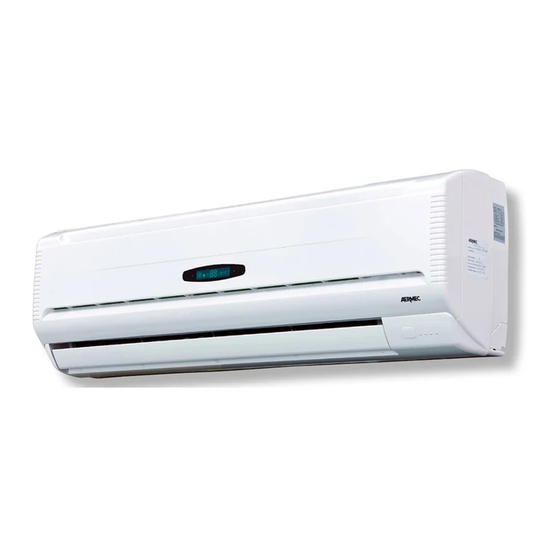
Wall-mounted fan coil unit
Hide thumbs
Also See for FCW Series:
- Installation and user manual (125 pages) ,
- Installation booklet (19 pages) ,
- Installation and user manual (116 pages)
Advertisement
Quick Links
VENTILCONVETTORE PER INSTALLAZIONE A PARETE
GEBLÄSEKONVEKTOR FÜR WANDINSTALLATION
ENTILOCONVECTOR PARA INSTALACIÓN DE PARED
IT
pag.5
FCW 222V
FCW 322V
FCW 422V
FCW 223V
FCW 323V
FCW 423V
GB
FR
DE
pag.26
pag.47
pag.68
FCW
FCW 22VL
FCW 223VN
FCW 32VL
FCW 323VN
FCW 42VL
FCW 423VN
FCW 222VN
FCW 22VLN
FCW 322VN
FCW 32VLN
FCW 422VN
FCW 42VLN
ES
pag.89
IFCW3LJ 1508 - 5138800_00
Advertisement

Related Manuals for AERMEC FCW Series


Summary of Contents for AERMEC FCW Series
- Page 1 VENTILCONVETTORE PER INSTALLAZIONE A PARETE GEBLÄSEKONVEKTOR FÜR WANDINSTALLATION ENTILOCONVECTOR PARA INSTALACIÓN DE PARED FCW 222V FCW 22VL FCW 223VN FCW 322V FCW 32VL FCW 323VN FCW 422V FCW 42VL FCW 423VN FCW 223V FCW 222VN FCW 22VLN FCW 323V FCW 322VN FCW 32VLN FCW 423V FCW 422VN...
- Page 2 MODÈLE PLUS ACCESSOIRES : Il est interdit de faire fonctionner l’appareil avec des accessoires qui ne sont pas fournis de Aermec. MODELL + ZUBEHÖR : Falls das Gerät mit Zubehörteilen ausgerüstet wird, die nicht von Aermec geliefert werden, ist dessen Inbetriebnahme solange untersagt.
- Page 3 Dear customer, TABLE OF CONTENTS Observations • Safety warnings • On receipt of the unit • Packaging • Disposal Maintenance • Troubleshooting Description of the unit Main components • Description of the components General information Important information • Operational limits Direction of the air flow Control keys and signals (FCW with microprocessor controller) TLW2 - Infra-red remote control...
- Page 4 AERMEC S.p.A. accepts no liability for attention to the instructions for any damage due to improper use of the unit, or the failure to read the information contained in this manual fully and carefully.
- Page 5 The ordinary maintenance can be carried out by the user and Special maintenance can only be performed by Aermec consists of a series of simple operations, which will ensure that After-Sales Services or by people with the technical and the fan coil unit operates at full efficiency.
- Page 6 The fan coil unit is a terminal unit for The fan coil unit is designed to ensure which then requires a cable connected conditioning internal air both in winter maximum compliance with safety accessory panel or connection to the and summer. regulations.
-
Page 7: Front Panel
Front panel Auxiliary emergency switch Horizontal air discharge blades Electric terminal connections Vertical air discharge blades Front case Air filter Frame Heat exchanger coil 10 Display Colour Pantone Code: GRIS 1C RAL Code: 9010 TLW2 PFW2 FRONT PANEL tion, as an alternative to the PFW2 wired The air intake is via the slots. - Page 8 5 SLAVE fa coil units for each zone). on the fan coil unit (only for the models turning on, turning off and all the fan coil 4) Control of a fan coil unit system, plus man- (where it is possible) or be mounted into a unit control and programming operations.
-
Page 9: Operating Environment
........70 °C ......13 bar (1.3 MPa) Connect to a 230 V maximum and minimum room temperature limits, Ta, are and ensure it remains within the limit of ±10% with respect to respected: 0°C < Ta < 40°C ; R.H. < 85%. the nominal value. - Page 10 coil unit. DIRECTION OF THE AIR FLOW The blades on the air discharge are arranged to direct the air in two directions: – vertical blades, to be adjusted manually – motorised horizontal blades for versions with microprocessor controller, to be adjusted only by means of the TLW2 remote control or the PFW2 wired control panel –...
-
Page 11: Fan Speed
When the fan coil unit is powered up it emits a beep. When the fan coil unit is powered but not on, all the LEDs are off. Temperature Description Set temperature (normal operation) - Set temperature (flashing) (during setting) FAN SPEED - Water temperature in battery (see functions to activate the AUX button) - Water inlet temperature... - Page 12 coil unit. ON/OFF Turning on and off. Press this button to set the various operating modes: automatic (AUTO), cool- ing (COOL), dehumidification (DRY), heating (HEAT) and ventilation (FAN). Temperature control buttons (16 to 30 °C). Use these buttons to set the temperature you wish to have in the room, to increase the temperature and to decrease it.
- Page 13 With the remote control on (ON), the display shows the settings of the unit, with the remote control off (OFF) the display is off and only displays the timer for the programmed activation (if active). Shows the operating mode: ➀ AUTO automatic ventilation...
- Page 14 WIRED CONTROL PANEL coil unit. Turning the unit on and off. Press this button to set the various operating modes: automatic (AUTO), cooling (COOL), heating (HEAT) and ventilation (FAN). Press this button to enable the night comfort function (SLEEP). LOCK ➄...
- Page 15 The programme requires the system to circulate chilled or hot water. The fan coil unit comes on. The fan coil unit will automatically switch on in Cool mode, Heat mode or in the dead band (waiting) depending on the water temperature. Press the MODE key repeatedly until the word AUTO appears on the display (TLW2) or the LEDs on wired control panel (PFW2) turns on HEAT and COOL.
- Page 16 The programme requires the system to circulate chilled water. The fan coil unit comes on. The fan coil unit automatically starts in cooling mode. Press the MODE key repeatedly until the word COOL appears on the display (TLW2) or the LEDs on wired control panel (PFW2) turns on COOL. –...
- Page 17 The programme requires the system to circulate chilled water. The fan coil comes on and the display is switched on. Press the MODE key repeatedly until the word DRY appears on the display (TLW2) or the LEDs on wired control panel (PFW2) turns on DRY. –...
- Page 18 – Set the required conditions (MODE, FAN, TEMP) on the remote control that you want active when starting the unit. – Turn off with keys – The key with the symbol allows increases of 1 hour – The key with the symbol allows decreases of 1 hour The display only shows the hours the unit remains off before the unit is turned on, TLW2 from 1 to 18 hours,...
- Page 19 [mm] 1170 Ø70 Ø70 1170 Ø70 WARNING: correct operation. average water temperature should not In the specific case of electrical connec drop below the operating limits shown appropriate personal protection. in the manual determined by the room WARNING: temperature and humidity conditions. insulation resistance.
- Page 20 maximum operating temperature is not The service hole for the piping can be exceeded. located on the right or left of the unit. Instructions essential for the proper The support wall must be sturdy and not installation of the equipment are shown subject to vibrations.
- Page 21 nents of the unit paying attention that the debris from the materials used for the installation do not block the fan or obstruct the filters or the grilles. - After installation perform a functional test of the fan coil unit. Screws Screw covers Coil air vent...
-
Page 22: Electrical Wiring
ELECTRICAL WIRING Front panel Power supply terminal block Base WARNING: Ensure that the installation is wired in The electrical power cable must be of the compliance with the laws and standards operations on the unit. H07 V-K or N07 V-K type with 450/750V in force, and with the instructions in insulation rating if inside a tube or con- this manual. - Page 23 INSTALLATION OF PFW2 WIRED CON inside the fan coil unit. - connect connector (B) of the wired con- trol panel to the circuit board connector ing of the fan coil unit. Alternative to the now vacant. The PFW2 makes it possible to set the operating parameters of the unit and A PFW2 wired control panel can only con- these parameters are shown on a liq-...
Need help?
Do you have a question about the FCW Series and is the answer not in the manual?
Questions and answers