Advertisement
Table of Contents
- 1 Tools Needed
- 2 Average Time to Complete Process
- 3 STEP #1: Remove the Screws from the Base of the Unit
- 4 STEP #2: Expose the Motherboard
- 5 STEP #3: Unplug the Connections from the Motherboard
- 6 STEP #4: Remove the Connecting Cables/Wires from the Motherboard
- 7 STEP #5: Remove the Defective Motherboard from the Base-Plate
- 8 STEP #6: Install the New Motherboard
- Download this manual
USCutter
This tutorial assumes that previous trouble shooting with a USCutter Technical Support Representative has determined
your SC Series motherboard to require replacement. Your cutter should be un-plugged from power throughout this
process. There are a variety of issues that would require a motherboard replacement, all of them stemming from hardware
failures only. The most common causes for motherboard replacement are:
*
A grinding sound when you first turn the cutter on likely indicates that the carriage bracket in the back of the machine is not making contact with
the green limit switch. This can be the result of the carriage having come off the track and is not a Motherboard failure.
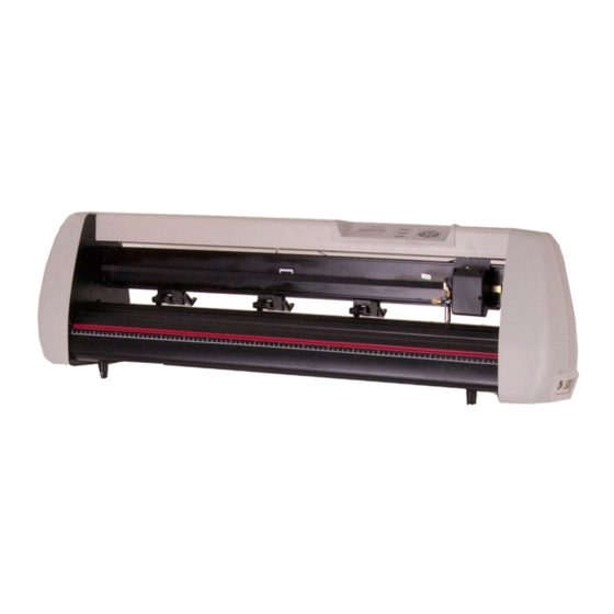
SC Series Motherboard
Replacement Guide
Tools needed
:
Philips Screw driver
Small or Needle nose pliers
Tape & a Marker
Average time to complete process:
20 – 30 mins
Jerky or inconsistent movement of the carriage or feed-rollers when "jogging" or
changing the home origin on the cutter.
Grinding sound when "jogging" the feed-rollers or carriage* or no movement at all
Unidentifiable characters (gibberish) displayed on the cutter's LCD screen
Flashing lights on the menu and/or carriage arm jumping up and down repeatedly
Advertisement
Table of Contents

Related Manuals for USCutter SC Series


Summary of Contents for USCutter SC Series
- Page 1 This tutorial assumes that previous trouble shooting with a USCutter Technical Support Representative has determined your SC Series motherboard to require replacement. Your cutter should be un-plugged from power throughout this process. There are a variety of issues that would require a motherboard replacement, all of them stemming from hardware failures only.
- Page 2 STEP #1: Remove the screws from the base of the unit. The motherboards in the SC series cutters are located inside and underneath the unit, on the right side.
- Page 3 STEP #2: Expose the Motherboard The wires that connect the motherboard to all the other components in the unit come from two different directions, and will be taught. When you lower the base plate, try to “tuck” the plate into the frame of the cutter, so as not to place too much tension or stress on the wires and connecting ports.
- Page 4 STEP #3: Unplug the connections from the Motherboard. There are a total of 8 connections on the Motherboard. Yours should look something similar to the image below. Before we start to un-plug anything, there are a couple prep-steps we’ll want to take first. Four of the eight connections on the Motherboard are inter-changeable, so it’s recommended that you mark all the wires prior to removing them.
- Page 5 Next, you’ll need to break loose the hot glue on the larger connections. The hot glue was meant to prevent the ports from wiggling loose during shipping and it isn’t not critical. Use your small/needle-nose pliers and carefully remove the hot glue from around the ports STEP #4 : Remove the connecting cables/wires from the motherboard.
- Page 6 STEP #5: Remove the defective motherboard from the base-plate Now that you have the cables and wires disconnected from the mother board; there are 4 machine screws that will need to be removed. These screws are what hold the Motherboard to the base-plate.
- Page 7 STEP #6: Install the new motherboard! Set the defective motherboard aside and attach the new motherboard to the base-plate. Next, using the labels on the wires as a reference, reconnect the wires and cables to the new Motherboard ensuring they get a solid connection. Once you have everything reconnected (as pictured below) you can fold the base plate back up to the bottom of the cutter and replace all the base-plate machine screws.
Need help?
Do you have a question about the SC Series and is the answer not in the manual?
Questions and answers