
Related Manuals for Hankscraft Runxin RevV4

Summary of Contents for Hankscraft Runxin RevV4
- Page 1 Innovative Solutions for Your Water RevV4 Valves & Systems Service Manual Hankscraft Runxin, LLC 300 Wengel Drive Reedsburg, WI 53959 608.524.9465 sales@hrh2o.com hrh2o.com...
-
Page 2: Table Of Contents
RevV4 Valves & Systems Service Manual Table of Contents 1. Introduction ..............................4 2. Product Features and Applications ......................5-6 3. Product Dimensions and Specifications ...................... 7-8 4. Pre-Installation Checklist ......................... 9-10 5. Valve Installation ........................... 11-14 a. Control Valve Installation ........................11-12 b. - Page 3 RevV4 Valves & Systems Service Manual 9. System Installation ..........................32-44 a. Plumbing Connections ......................... 32 b. Drain Line Installation .......................... 32 c. Brine Line and Brine Tank Installation ..................... 33-36 d. System Installation Chart ........................37 e. System Start-Up..........................38-39 Sanitization Procedure .........................
-
Page 4: Introduction
There is an alternate interlock function, used with twin demand systems and 3-way ball valves to supply treated water 24/7. The RevV4’s simple, yet powerful user interface has an easy to read LCD display and the valve offers remote handling to accept input from a PLC or computer. Advanced work modes are available with adjustable settings and three different cycle sequences to get the exact configuration needed for any job. -
Page 5: Product Features And Applications
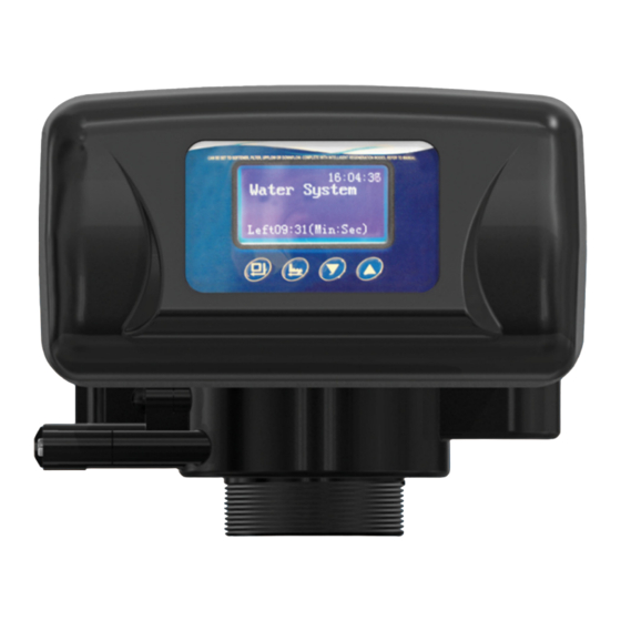
Mechanical Components The RevV4 uses internal ceramic discs which are corrosion and abrasion resistant to form a hermetic seal. Rotation of the upper disc aligns to the corresponding lower disc ports for Service, Backwash, Brine & Slow Rinse, Brine Refill and Fast Rinse modes. - Page 6 RevV4 Valves & Systems Service Manual LCD Display Screen Advanced Valve and External Device Connections Interlock and Alternate Interlock • Remote Handling • Solenoid Valve • 7 Regeneration Mode Options with Adjustable Cycle Times Maximum Day Regeneration Interval When the valve reaches the maximum programmed service days, without reaching the set service capacity, it will trigger a regeneration at the pre-programmed time of day.
-
Page 7: Product Dimensions And Specifications
RevV4 Valves & Systems Service Manual 3. Product Dimensions and Specifications Length (max.) Width (max.) Height (max.) Regeneration Mode 8.3" 8.75" 7.5" Up-flow These valve dimensions are for reference only. Connect Port Dimensions Product Model Inlet Port Outlet Port Drain Port... - Page 8 RevV4 Valves & Systems Service Manual A-01 Meter Delay: Regeneration happens when the capacity reaches zero and the preset time of regeneration is reached. A-02 Meter Immediate: Regeneration happens when the capacity reaches zero. A-03 Intelligent Meter Delay: The same delay function as A-01 but the capacity is determined by entering the total Resin Capacity, Feed Water Hardness, and the Number of People in the household.
-
Page 9: Pre-Installation Checklist
RevV4 Valves & Systems Service Manual 4. Pre-Installation Checklist IMPORTANT NOTICE Read through the instructions thoroughly and obtain all materials and tools before proceeding with the installation. Be sure to follow all applicable national, state, county and local plumbing codes and regulations. - Page 10 Do not use the system with water that is microbiologically unsafe or of unknown quality without • adequate disinfection before or after the system. Do not use the brine tube, injector body, or other connectors on the RevV4 valve as a handle to carry • the system.
-
Page 11: Valve Installation
Install the unit in an environment which minimizes consumer risk of loss in the event of malfunction. • Hankscraft Runxin offers many different products for many different applications, for both indoor and • outdoor environments. If you are not 100% sure the equipment purchased is suitable for the installation application or environment, please check with a Hankscraft representative, or your local equipment provider, to ensure the proper equipment is selected. -
Page 12: Control Valve Installation
See Product Sizing Chart on Page 13. 3. Install Valve Base O-ring around the neck of the valve. 4. Lubricate the center hub O-ring of the RevV4 valve. Figure 5-1 5. Install the top basket with a twist and lock action to center hub of the RevV4 valve. -
Page 13: System Sizing Chart
RevV4 Valves & Systems Service Manual System Sizing Chart Resin Total Tank Salt Injector Volume System Color DLFC Part No. Color BLFC Part No. Color Size Setting Part No. cu. ft. Grains 9x48 0.9375 16,577 6302 Pink 2.02 8468060 White... -
Page 14: Control Valve Configuration
RevV4 Valves & Systems Service Manual Control Valve Configuration (refer to chart on Page 13 for specific recommendations) Drain Line Flow Control (DLFC) Button Installation If you wish to change the DLFC button, unscrew drain barb collar and remove drain barb. -
Page 15: Ceramic Bypasses
RevV4 Valves & Systems Service Manual Ceramic Bypasses 41206 Hankscraft Runxin, LLC 300 Wengel Drive 608.524.9465 hrh2o.com sales@hrh2o.com... -
Page 16: Programming
RevV4 Valves & Systems Service Manual 7. Programming: Display and Instructions Manual / Delayed Regeneration 1. Pressing at any time results in an immediate manual regeneration. 2. Pressing and holding for 3 seconds, when system is locked, results in a delayed regeneration at the preselected time. - Page 17 Allows you to set the Regen Cycle and Regen Mode that will work best for your customer; as well as adjust or set each phase time. To enter advanced programming, follow the directions below. 1. Plug in the RevV4. Immediately press in sequence to enter into the advanced setting.
-
Page 18: Programming Modes A-01 To A-07
Review Regen Times Displays the number of times the valve has regenerated independently. Review Software Ver. Shows current software version of RevV4 valve. Above parameters are located in standard program settings menu. (*) Denotes parameters located in advanced program settings menu. - Page 19 Review Regen Times Displays the number of times the valve has regenerated independently. Review Software Ver. Shows current software version of RevV4 valve. Above parameters are located in standard program settings menu. (*) Denotes parameters located in advanced program settings menu.
- Page 20 Review Regen Times Displays the number of times the valve has regenerated independently. Review Software Ver. Shows current software version of RevV4 valve. Above parameters are located in standard program settings menu. (*) Denotes parameters located in advanced program settings menu.
- Page 21 Review Regen Times Displays the number of times the valve has regenerated independently. Review Software Ver. Shows current software version of RevV4 valve. Above parameters are located in standard program settings menu. (*) Denotes parameters located in advanced program settings menu.
- Page 22 Review Regen Times Displays the number of times the valve has regenerated independently. Review Software Ver. Shows current software version of RevV4 valve. Above parameters are located in standard program settings menu. (*) Denotes parameters located in advanced program settings menu.
- Page 23 Review Regen Times Displays the number of times the valve has regenerated independently. Review Software Ver. Shows current software version of RevV4 valve. Above parameters are located in standard program settings menu. (*) Denotes parameters located in advanced program settings menu.
- Page 24 Review Regen Times Displays the number of times the valve has regenerated independently. Review Software Ver. Shows current software version of RevV4 valve. Above parameters are located in standard program settings menu. (*) Denotes parameters located in advanced program settings menu.
-
Page 25: Pcb Functions And Connections
RevV4 Valves & Systems Service Manual 8. PCB Functions and Connections Overview Function Application Explanation Optional to prevent water flow from outlet or Outlet solenoid valve controlling a liquid level holding tank. Signal Output Connector b-01 Increase pressure for regeneration or backwash. -
Page 26: Signal Output
RevV4 Valves & Systems Service Manual Signal Output The two types of output modes are b-01 and b-02. The output signal connector is designed to drive several different types of electrical devices. (Refer to Figures 8-1 to 8-7) b-01 Switches the signal at the start of a regeneration and shuts off at the end of a regeneration. -
Page 27: Signal Output Connector
Signal Output Connector Solenoid Valve on Outlet (set b-01) Function: Valve is normally open. When the RevV4 is in backwash there is no signal output. The solenoid valve is closed and no water flows through the RevV4 to the holding tank. - Page 28 Function: When the RevV4 is in Service, Backwash, Brine & Slow Rinse, Brine Refill and Fast Rinse the solenoid valve is open. When the RevV4 is switching the solenoid valve is closed and no water flows through the RevV4. Also prevents water hammering in high psi applications.
- Page 29 RevV4 Valves & Systems Service Manual Function: When the RevV4 is in service and the water level in the tank is low the pump starts up. If the water tank has enough water the switch for the liquid level controller is closed and the pump turns off. When the RevV4 is in regeneration the inlet always requires water.
-
Page 30: Interlock
Function: With parallel installation only one valve regenerates at a time. Refer to Figure 8-8. Figure 8-8 Interlocking a Network of Valves. Use Interlock cable to connect CN8 to CN7 to the next RevV4 in the series. If one interlock cable is disconnected, the system is divided into two individual systems. -
Page 31: Remote Handling Connector
RevV4 Valves & Systems Service Manual Remote Handling Connector Function: Online TDS meter monitor, PLC or computer to control the regeneration schedule. When the controller receives a contact closure from one of the above instruments, regeneration begins. Refer to Figure 8-10. -
Page 32: Using One Flow Meter With Interlock
Function: Allows for continuous service and simultaneous non overlapping regeneration. This application is for 2 or more RevV4’s in a system, all in service, with one flow meter for the entire system. Adjust the Time Clock valve to the maximum days. This avoids a regeneration prior to the metered valve reaching capacity. -
Page 33: Brine Line And Brine Tank Installation
RevV4 Valves & Systems Service Manual Brine Line Connection 1. As Figure 9-3 shows; slide brine nut onto the 3/8" brine tubing. 2. Install the filter screen into the ferrule and insert the ferrule into the end of brine tube. - Page 34 RevV4 Valves & Systems Service Manual 3. Assemble salt grid (4 feet, 1 base). Feet clip into the bottom of the base. 4. Insert assembled salt grid into brine tank by lining up the cut out hole with the drilled holes on the brine tank.
- Page 35 RevV4 Valves & Systems Service Manual 6. Insert the brine well, making sure the bottom brine well cap is attached. Insert the float assembly by lining up the top cut out holes. Through testing there have been some instances where the bottom float assembly cap can come off of the tube when force is applied.
- Page 36 RevV4 Valves & Systems Service Manual 9. Install overflow elbow fitting with washer on the outside of tank. Fasten nut on the inside of the tank. 10. Replace brine well lid. 11. Replace brine tank lid. Hankscraft Runxin, LLC 300 Wengel Drive 608.524.9465...
-
Page 37: System Installation Chart
RevV4 Valves & Systems Service Manual System Installation Chart Hankscraft Runxin, LLC 300 Wengel Drive 608.524.9465 hrh2o.com sales@hrh2o.com... -
Page 38: System Start-Up
RevV4 Valves & Systems Service Manual System Start-Up 1. Before running the RevV4 for the first time, flush out the water line and bypass. Be sure the bypass is closed. 2. Turn the water source on at the inlet to the house. - Page 39 RevV4 Valves & Systems Service Manual 15. Next to fill the brine tank with water press to manually advance through the next phase, fast rinse, until you reach B.R. (brine refill). 16. Once you reach B.R. (brine refill) allow this phase to run, do not advance past this phase. This will automatically fill the brine tank with the correct amount of water.
-
Page 40: Sanitization Procedure
RevV4 Valves & Systems Service Manual Sanitation Procedure At the start up or after service, the following procedure is recommended to exclude the possibility of microbiological contamination of the system. This procedure relates only to the original description of equipment and options described for this system. Any alterations to the configuration would require evaluation by a trained water professional. -
Page 41: Water Flow Diagrams
RevV4 Valves & Systems Service Manual Water Flow Diagrams Service Position Raw water enters into the control valve from water inlet A, from the top of valve core and into the tank from top distributor. Then the water moves down through the resin layers,... - Page 42 RevV4 Valves & Systems Service Manual Brine Draw Position Raw water enters into control valve from water inlet A, through valve core into injector inlet F, into the injector outlet E. This produces negative pressure so the brine is drawn into the valve. Water flow then goes...
- Page 43 RevV4 Valves & Systems Service Manual Secondary Backwash Position Raw water enters into the control valve from water inlet A, through valve body from the top of valve core, then travels down through the riser tube and up through the resin, into the valve core, and finally flows out from drain outlet C.
- Page 44 RevV4 Valves & Systems Service Manual Fast Rinse Position Raw water enters into the control valve from water inlet A, through the top of the valve core, into the tank from the top, down the riser pipe through bottom strainer and up through the resin layers, through valve core and flows out to drain outlet C.
-
Page 45: Assembly Drawings And Parts List
RevV4 Valves & Systems Service Manual 10. Assembly Drawings and Parts List Hankscraft Runxin, LLC 300 Wengel Drive 608.524.9465 hrh2o.com sales@hrh2o.com... -
Page 46: Valve Parts List
RevV4 Valves & Systems Service Manual Item Item Description Part No. Qty. Description Part No. Qty. O-ring, 32.5X3.55 8378116 Screw, Cross ST3.9X13 8909013 O-ring, 73x5.3 8378143 Screw, Cross M4×12 8902005 Screw, Cross ST2.9X16 8909010 Small Gear 8241019 Valve Body 8022742... -
Page 47: Troubleshooting
RevV4 Valves & Systems Service Manual 11. Troubleshooting Control Valve Problem Cause Correction A. Electrical service to unit has been A. Check for consistent electrical service. interrupted. B. Reset regeneration cycles. 1. Softener fails B. Regeneration cycles set incorrectly. C. Replace controller. - Page 48 RevV4 Valves & Systems Service Manual A. Iron in the water supply pipes. A. Clean the water supply pipe. 7. Pressure lost B. Iron mass in the softener. B. Clean valve and add resin cleaning chemical, increase or iron in C.
-
Page 49: Electronics
RevV4 Valves & Systems Service Manual Electronics Problem Cause Correction A. Wiring to the front panel is loose. A. Check and replace the wiring. B. Control board is faulty. B. Replace control board. 1. Abnormal C. Transformer malfunction. C. Check and replace transformer. -
Page 50: Replacement Parts
RevV4 Valves & Systems Service Manual 12. Replacement Parts Description Part Number Quantity Brine Assembly Kit, 3/8" - #63, #64, #65, #66, #68, #73 REVV-217 Brine Screen and Tube - #63, #65 REVV-218 Bypass Clip 8270004 Control Board Kit - #35, #37, #39... -
Page 51: Accessories
RevV4 Valves & Systems Service Manual 13. Accessories Description Part Number Figure Quantity Dust Cover 72605-CV Animated Connector with Flow Meter AC/FM-F82 1 Pair 1" Inlet/Outlet Female to Female Adaptor REVV-208 ¾" 90 ⁰ Inlet/Outlet Elbow REVV-209 1" 90 ⁰ Inlet/Outlet Elbow REVV-210 ¾"... -
Page 52: Packing List
RevV4 Valves & Systems Service Manual 14. Packing List Valve Packing List Description Part Number Figure Qty. 72605-HK Control Valve 72605B-HK 12VDC Transformer 6379021 User Manual Parts Valve Base O-ring 8378143 Interlock Cable 5515002 Washers 8371001 Filter Screen & Bushing... -
Page 53: System
Hankscraft Runxin warrants to the original owner that the items listed below, excluding but not limited to wear parts like O-rings, gaskets and seals, will be free from defects in materials and workmanship for the period of time specified below from the original purchase date. - Page 54 Any parts used for replacement are warrantied for the remainder of the original warranty period applicable to the part from the date of manufacture so long as the parts are installed by a Hankscraft Runxin factory trained and authorized installer.
-
Page 55: System Configuration And Settings
RevV4 Valves & Systems Service Manual 16. System Configuration and Settings Installer Name: ________________________________________________________________________________________ Address: _____________________________________________ City/State:_________________________________ Phone: ____________________________________________ Install Date: _________________________________ Softener System Configuration Tank Size: Dia. In Height in Resin Volume: cu/ft. Brine Tank Capacity: 100L 130L Media: ________________________________________________________________________________________... -
Page 56: Factory Default Settings
RevV4 Valves & Systems Service Manual 17. Factory Default Settings Parameter Unit Factory Default Programmed Settings Language English Program Type Interlock Regeneration Sequence Water Treatment Capacity (A-01,02,03,04,05,07) Gallons 2100 Number of People in Household (A-03) Regeneration Mode (A-01,02,03,04,05,06,07) A-03 Regeneration Time 24-hr. -
Page 57: Contact Information
RevV4 Valves & Systems Service Manual 18. Contact Information Innovative Solutions for Your Water Hankscraft Runxin, LLC 300 Wengel Drive Reedsburg, WI 53959 608.524.9465 sales@hrh2o.com hrh2o.com Hankscraft Runxin, LLC 300 Wengel Drive 608.524.9465 hrh2o.com sales@hrh2o.com...
Need help?
Do you have a question about the RevV4 and is the answer not in the manual?
Questions and answers
How do I get into advanced programming mode so that I can switch to style a01? The sequential buttons the manual suggested don’t seem to work. Perhaps there’s a special technique? Please let me know (or point me to a video).