
Subscribe to Our Youtube Channel
Related Manuals for Gastro-M MILAN Series

Summary of Contents for Gastro-M MILAN Series
- Page 1 INSTRUCTIONS FOR USE AND MAINTENANCE ELECTRIC OVENS FOR PIZZA MILAN - ROME - NAPELS ENGLISH...
- Page 2 OVEN REV 03 19/06/2018 ENGLISH...
- Page 3 WARNING! BEFORE SWITCHING ON THE OVEN: REMOVE THE REFRACTORY STONES CAREFULLY, REMOVE THE POLYSTYRENE UNDER ALL THE STONES, AND THEN PUT AGAIN THE STONES INSIDE THE ROOM OF THE OVEN. ВНИМАНИЕ! ПЕРЕД ПЕРВЫМ ВКЛЮЧЕНИЕМ ПЕЧИ ОСТОРОЖНО ПРИПОДНЯТЬ ШАМОТНЫЙ КАМЕНЬ И ДОСТАТЬ...
-
Page 4: Table Of Contents
INDEX MARKING PLATE ......................4 SERIAL LABEL ........................4 GENERAL INFORMATION ....................4 THE IMPORTANCE OF THE MANUAL ..................4 STATUS OF “TURNED OFF OVEN” ..................4 WARRANTY ........................4 TECHNICAL DESCRIPTIONS .................... 5 TECHNICAL DATA ......................5 DESTINATION OF USE ......................8 LIMITS OF USE........................ -
Page 5: Marking Plate
MARKING PLATE SERIAL LABEL The plate bears in readable and indelible way the following data: - Name of the manufacturer; - Serial number ; - CE marking; - Electric voltage and frequency (Volt/Hz); - Model (MOD); - Year of construction ; -Electric power (kW/A);... -
Page 6: Technical Descriptions
TECHNICAL DESCRIPTIONS TECHNICAL DATA MILAN MILAN ROME ROME NAPELS NAPELS Measur ement unit °C 45-455 Temperature control L 130,5 L 130,5 L 100,0 L 100,0 L 136,0 L 136,0 P 60,0 P 60,0 P 95,5 P 95,5 P 95,5 P 95,5 External dimensions H 41,3 H 74,5... -
Page 7: Destination Of Use
DESTINATION OF USE The foreseen use for which this oven has been designed and produced is the following: FORESEEN USE: PIZZA BAKING, GRATINATING OF GASTRONOMY PRODUCTS AND HEATING OF FOODSTUFF IN BAKING PANS. THE OVEN CAN BE USED EXCLUSIVELY BY AN AUTHORIZED OPERATOR (USER). THIS APPLIANCE INTENDED... -
Page 8: Electric Connection
ELECTRIC CONNECTION ELECTRIC CONNECTION OVEN MAINS MUST COMPULSORILY EXCLUSIVELY PERFORMED AUTHORIZED TECHNICIAN (ELECTRICIAN) SATISFYING THE TECHNICAL AND PROFESSIONAL REQUIREMENTS STATED BY THE REGULATIONS IN FORCE IN THE COUNTRY OF USE OF THE OVEN, WHO MUST ISSUE A DECLARATION OF CONFORMITY FOR THE INTERVENTION PERFORMED. -
Page 9: Terminal Box
TERMINAL BOX The terminal box is placed externally on the back of the oven. Oven type N. of cables Section (mm²) Single phase, one chamber Single phase, two chambers and versions 9 single phase Three phase one chamber and two chambers Three phase from versions 9 and up EQUIPOTENTIAL The equipment must be connected with an equi-potential system . -
Page 10: Use And Functioning
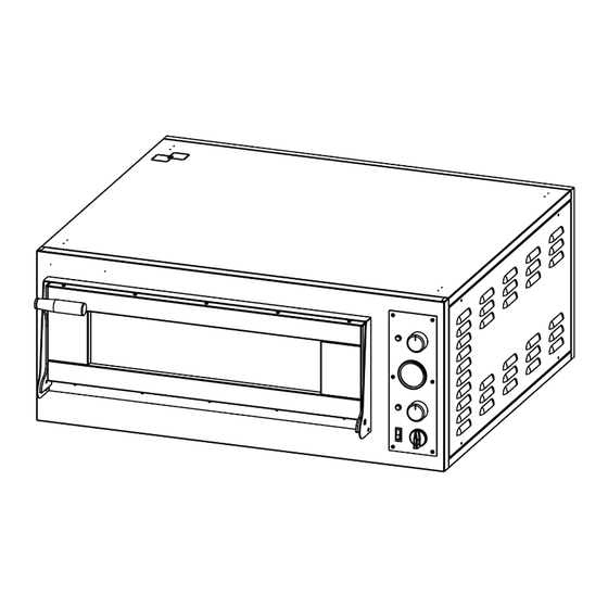
USE AND FUNCTIONING CONTROL PANEL REF. DENOMINATION FUNCTION Warning light If lighted, it signals the operation of the resistor in use. • Pos.0:it disables the operation of the resistor; Thermostat • Pos. 0-500°C :it enables the operation of the resistor and sets the wished temperature. -
Page 11: First Commisioning
FIRST COMMISIONING Remove the polystyrene underneath the refractory stones and the protective film avoiding using tools that can damage the surfaces. FOR THE SAFETY REASONS, THE MAXIMUM TEMPERATURE ALLOWED TO BE SET IS 500°C. THE FIRST COMMISSIONING CAN BE CARRIED OUT ONLY AFTER AN INSTALLATION CARRIED OUT BY AUTHORIZED PERSONEL WHO WILL ISSUE A DECLARATION OF CONFORMITY. -
Page 12: Maintenance
MAINTENANCE BEFORE PERFORMING ANY TYPE OF MAINTENANCE INTERVENTION, IT IS COMPULSORY TO DISCONNECT THE PLUG OF THE OVEN FROM THE POWER SUPPLY OUTLET. CLEANING The clearing must be done every time the oven has been used following all the rules to prevent malfunctioning of the oven and for hygienic purpose. -
Page 13: Spare Parts
SPARE PARTS ONE CHAMBER OVEN EXLODED VIEW... - Page 14 TWO CHAMBER OVEN EXLODED VIEW...
-
Page 15: Exploded View
DOOR EXPLODED VIEW... - Page 17 CONTROL UNIT EXPLODED VIEW...
-
Page 18: Spare Parts
SPARE PARTS MILAN 1 MILAN 2 ROME 1 ROME 2 NAPELS 1 NAPELS 2 5M200030 5M200030 5M200030 5M200030 5M200030 5M200030 7M010007 7M010007 7M010005 7M010005 7M010007 7M010007 5M200016 5M200016 5M200016 5M200016 5M200016 5M200016 4P100007 4P100007 4P100007 4P100007 4P100007 4P100007 3R030001 3R030001 3R030001 3R030001 3R030001... -
Page 19: Electric Equipment
ELECTRIC EQUIPMENT LIST OF COMPONENTS MARK DESCRIPTION Single (1) pole thermostat Three (3) poles thermostat Heating elements on/off switch Heating elements spy light QF0/1 Chamber light on/off switch Contactor Timer... -
Page 20: Wiring Diagrams
WIRING DIAGRAMS MILAN ROME 400V/3PH (one chamber) - Page 21 MILAN ROME 230V/1PH (one chamber)
- Page 22 MILAN ROME 230V/3PH (one chamber)
- Page 23 NAPELS 400V/3PH (one chamber)
- Page 24 NAPELS 230V/1PH (one chamber)
- Page 25 NAPELS 230V/3PH (one chamber)
Need help?
Do you have a question about the MILAN Series and is the answer not in the manual?
Questions and answers