Table of Contents
Advertisement
Quick Links
Advertisement
Table of Contents

Summary of Contents for JUMO B 70.9040
-
Page 1: Operating Instructions
Thyristor Power Units B 70.9040 Operating Instructions 05.01 /00089951... -
Page 3: Table Of Contents
Contents Introduction ..................7 Preface ........................7 Typographical conventions ................... 8 1.2.1 Warnings ........................8 1.2.2 Note signs ....................... 8 Description ......................9 Type designation ....................9 1.4.1 Type extensions (extra codes) ................10 1.4.2 Standard accessories .................... 10 1.4.3 Accessories ......................11 Block diagram ...................... - Page 4 Contents Free-running economy circuit, purely resistive loads ........30 Master-slave economy circuit, with resistive/inductive loads ......31 Commissioning ................. 33 Adjust control input (full wave) ................33 5.1.1 Setting the maximum power output ............... 33 5.1.2 Input signal attenuator ................... 33 Setting the base load ...................
- Page 5 Contents Faults ....................53 Fault-finding ......................53 Replacing the semiconductor fuse ..............53 8.2.1 Type TYA-110/3, 025 to 100, ................. 53 8.2.2 Type TYA-110/3, 150, .................... 54 8.2.3 Type TYA-110/3, 250, .................... 54 Power units 05.01...
- Page 6 Contents Power units 05.01...
-
Page 7: Introduction
1 Introduction 1.1 Preface Please read these operating instructions before starting up the instrument. Keep them in a place that is accessible to all users at all times. Please help us to improve this manual. Your suggestions will be welcome. Fax: in Germany (0661) 6003-862... -
Page 8: Typographical Conventions
1 Introduction 1.2 Typographical conventions 1.2.1 Warnings The signs for Danger and Caution are used in this manual under the following conditions: Danger This symbol is used where there may be danger to personnel if the instruc- tions are disregarded or not followed accurately! Caution This symbol is used where there may be damage to equipment or data if the instructions are disregarded or not followed accurately! -
Page 9: Description
1 Introduction 1.3 Description Application A thyristor power unit can be used wherevere sizeable resistive or inductive loads are switched frequently – for instance, in industrial furnaces and plastics processing. Operating The thyristor power units can operate under phase-angle control with adjust- modes able current limiting or in burst-firing mode, depending on the setting of the in- ternal switch. -
Page 10: Type Extensions (Extra Codes)
1 Introduction TYA-110/3 ..Thyristor power unit for analog control Load current 25A Load current 50A Load current 75A Load current 100A Load current 150A Load current 250A Rated load voltage 24V Rated load voltage 42V Rated load voltage 115V Rated load voltage 230V Rated load voltage 265V... -
Page 11: Accessories
1 Introduction 1.4.3 Accessories Super-fast semiconductor fuses to protect the thyristors from short-circuits (no supply line fusing). 32A for I = 25A, Sales No. 70/00068009 80A for I = 50A, Sales No. 70/00068011 125A for I = 75A, Sales No. 70/00081800 160A for I = 100A, Sales No. -
Page 12: Front Panel Indicators And Adjustments
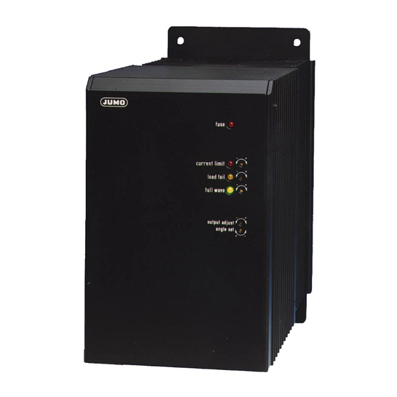
1 Introduction 1.6 Front panel indicators and adjustments Indicator LED for blown semiconductor fuse Adjustment of threshold for part-load failure indication (with extra code TR or TO) LED for current indication Adjustment of full output LED for load-failure indication Adjustment of power level signal LED for full-output indication Spring clip to release cover Adjustment of current limit in phase-angle... -
Page 13: Operating Modes
2 Operating modes 2.1 Phase-angle control with soft start and current limiting In this mode of operation, the power is regulated by altering the phase angle. This method is suitable for transformer and resistive loads. During the switch- on period the phase-angle is gradually advanced by the controller to provide a soft start. -
Page 14: Burst-Firing Operation, For Resistive Loads
2 Operating modes 2.2 Burst-firing operation, for resistive loads In this mode of operation, the power is regulated by changing the number of full-wave cycles of the supply line voltage which are switched on during each control period. This method is used for purely resistive loads which have a cold resistance that is roughly the same as the hot resistance. -
Page 15: Burst-Firing Operation For Transformer Loads And Loads With A High Positive Temperature Coefficient Tc (Mixed Operation)
2 Operating modes 2.3 Burst-firing operation for transformer loads and loads with a high positive temperature coefficient TC (mixed operation) It is not possible to change over to phase-angle control in this mode of operation. Soft start For the first switch-on of the thyristor power unit, or after being switched off by inhibiting the firing-pulses, after a supply line interruption, or if the setpoint was switched off for more than 8seconds, there will always be a short phase- angle controlled start (area a in the diagram). - Page 16 2 Operating modes For transformer loads, the thyristor power unit operates in burst-firing mode with a cut-back (retarded) phase-angle for the first half-wave. The factory set- ting is an angle α = 90°. This value can be altered on the front panel over a range α...
-
Page 17: Installation
3 Installation 3.1 Important installation notes Safety - The choice of cable, installation and electrical connection of the instrument regulations must meet the requirements of VDE 0100 “Regulations for the Installation of Power Circuits with nominal voltages below 1000 V AC” or the corresponding local regulations. -
Page 18: Filtering And Interference Suppression
3 Installation Switch-on The supply voltages for the load and control circuitry must be switched on sequence at the same time. In no circumstances should the supply voltage for the control electronics be switched on before the voltage for the load! This is especially important for operating transformer loads and re- sitive loads with a large variation between hot and cold resistance! Control inputs... -
Page 19: Wall Mounting
3 Installation above the unit. The thyristor power unit has enclosure protection IP00, and so it must be mounted in such a way that bodily contact is prevented (built-in unit). The heatsink can become very hot in operation! Incorrect use - The unit is not suitable for installation in areas with an explosion hazard (Ex areas). -
Page 20: Tya-110/3,150 And Tya-110/3, 250
3 Installation 3.4.2 TYA-110/3,150 and TYA-110/3, 250 Power units 05.01... -
Page 21: Din Rail Mounting
3 Installation 3.5 DIN rail mounting h Fix the DIN rail h Snap the thyristor power unit and its mounting plate onto a standard rail (to DIN EN 50 022) and lock it in place with the lever. This type of mounting is only possible for thyristor power units up to 50A rated current. - Page 22 3 Installation Power units 05.01...
-
Page 23: Electrical Connection
4 Electrical connection 4.1 Connection diagram The diagram shows the various connections that are available at the plug-in screw terminals. Only properly qualified personnel are permitted to make electrical connections! h Disconnect the equipment completely (on all poles) from the supply line h Connect the control cables (conductor cross-section 0.2 —... - Page 24 4 Electrical connection Connection for Pin assignment Symbol Supply voltage for control electronics; (line / phase 1) link V to N/L2, unless economy circuit is being used N/L2 (neutral / phase 2) Load connection Current input (differential input) Voltage input 3⊥...
-
Page 25: Type Tya-110/3, 025, - 050, - 075, - 100
4 Electrical connection 4.1.1 Type TYA-110/3, 025, - 050, - 075, - 100, ... 4.1.2 Type TYA-110/3, 150, ... 4.1.3 Type TYA-110/3, 250, ... Power units 05.01... -
Page 26: Single-Phase Operation: Line/Phase - N
4 Electrical connection 4.2 Single-phase operation: line/phase – N = phase-phase voltage = total controlled power = phase-neutral voltage = current in phase conductor = voltage on thyristor power unit I = current in thyristor power unit Power units 05.01... -
Page 27: Single-Phase Operation: Phase - Phase
4 Electrical connection 4.3 Single-phase operation: phase – phase = phase-phase voltage = total controlled power = phase-neutral voltage = current in phase conductor = voltage on thyristor power unit I = current in thyristor power unit Power units 05.01... -
Page 28: Star Configuration: With Star Point Connected To N
4 Electrical connection 4.4 Star configuration: with star point connected to N = phase-phase voltage = total controlled power = phase-neutral voltage = current in phase conductor = voltage on thyristor power unit I = current in thyristor power unit Power units 05.01... -
Page 29: Open Delta Configuration (Six-Wire Circuit)
4 Electrical connection 4.5 Open delta configuration (six-wire circuit) = phase-phase voltage = total controlled power = phase-neutral voltage = current in phase conductor = voltage on thyristor power unit I = current in thyristor power unit Power units 05.01... -
Page 30: Free-Running Economy Circuit, Purely Resistive Loads
4 Electrical connection 4.6 Free-running economy circuit, purely resistive loads Only possible in burst-firing mode with P-control = phase-phase voltage = total controlled power = phase-neutral voltage = current in phase conductor = voltage on thyristor power unit I = current in thyristor power unit Power units 05.01... -
Page 31: Master-Slave Economy Circuit, With Resistive/Inductive Loads
4 Electrical connection 4.7 Master-slave economy circuit, with resistive/inductive loads Only possible in burst-firing mode = phase-phase voltage = total controlled power = phase-neutral voltage = current in phase conductor = voltage on thyristor power unit I = current in thyristor power unit Power units 05.01... - Page 32 4 Electrical connection Power units 05.01...
-
Page 33: Commissioning
5 Commissioning 5.1 Adjust control input (full wave) The trimmer (7) “full wave” on the front panel can be used to adjust the thyris- tor power unit so that the 100% (full wave) firing point is reached at the maxi- mum output signal of the preceding controller. -
Page 34: Setting The Base Load
5 Commissioning 5.2 Setting the base load A base load can be set, in addition to the analog current input and the potenti- ometer input. Since these input signals are added together, the input signal gain must be corrected by adjusting the “full wave” trimmer (7). For instance, if a heating system is to be operated with a 33% base load, with the other 66% of the output being regulated by the controller, then the proce- dure is as follows:... -
Page 35: Setting The Current Limit
5 Commissioning 5.3 Setting the current limit Internal current Current limiting is only possible in the phase-angle mode of control. limiting h The trimmer (5) “current limit” on the front panel can be used to limit the effective (rms) value of the load current over a range from 10 — 100% of the rated current for the thyristor control unit (I ThyN 1.5 turns clockwise correspond to increasing the threshold by about 10%... -
Page 36: Alteration Of The Current Limit Imax, As A Function Of The Voltage On Terminal 9
5 Commissioning 5.3.1 Alteration of the current limit Imax, as a function of the voltage on Terminal 9 With an internal limit of, for example, I = 0.8 x I , the external range of variation is only 0 to 8V. 5.4 Setting the phase angle for the first half-wave In the mode “burst-firing with phase-angle controlled start”... -
Page 37: Load And Part-Load Failure Monitoring
5 Commissioning 5.5 Load and part-load failure monitoring This function is only available with the extra code TR or TO. If there is a change in the load resistance during operation, this is detected and indicated by the part-load failure monitoring. The signal output is available either as a floating contact (extra code TR) or an optocoupler (extra code TO). -
Page 38: Setting For Master-Slave And Free-Running Economy Circuit
5 Commissioning Alternative setting: Simulate a load failure, and then adjust the “load fail” trimmer so that the yel- low “load fail” LED just lights up. 5.5.2 Setting for master-slave and free-running economy circuit When using master-slave and free-running economy circuits, the settings must be made in both thyristor power units. -
Page 39: Settings
6 Settings 6.1 Opening the housing Adjustments must only be made while the unit is disconnected from the supply power! It is easier if these adjustments are carried out before the unit is installed. h Use a screwdriver to lever the spring fixing lug outwards. On the 150 A and 250 A versions: press both spring lugs inwards. -
Page 40: Adjustment Switches S1 - 21 And Pin Headers X503 / X504
6 Settings 6.2 Adjustment switches S1 — 21 and pin headers X503 / X504 The switches S1 to 21 can be found on the back of the printed circuit board. It is easier to access switches S15, S16 and S21 if the plug-in screw terminals are first pulled off downwards. - Page 41 6 Settings Power units 05.01...
-
Page 42: Summary Of Possible Settings
6 Settings 6.3 Summary of possible settings Switch position Switch number 10 11 12 13 14 15 16 17 18 19 20 21 factory setting job-specific setting Control input 0 — 20mA 4 — 20 mA 0 — 10V 2 — 10V 0 —... -
Page 43: Control Inputs
6 Settings 6.4 Control inputs The internal switches S1, S2, S16, S19, S20 can be used to adapt the thyris- tor power unit to suit the available control signal (controller output signal). There are separate voltage and current control inputs. The current inputs (+,-) are designed for a differential current signal, i.e. -
Page 44: Combinations Of External Potentiometer And Electronic Controller
6 Settings Logic control The thyristor power unit can also be operated by the following logical signals inputs (e.g. two-state/single-setpoint controller outputs): (switching pulse bursts on or off): - current signal 0/20mA (Terminals 1, 2) - voltage signal 0/10V (Terminals 3, 4) - floating contact (Terminals 4, 5) 6.4.1 Combinations of external potentiometer and electronic controller Controller with... -
Page 45: Subsidiary Control Loops
6 Settings Controller with This only uses the voltage input of the thyristor power unit. A 5 kΩ potention- voltage output meter is required on Terminals 3 and 5 for manual operation. Switch Automatic operation position 1 Manual operation position 2 6.5 Subsidiary control loops Subsidiary control loops are primarily used to eliminate or compensate exter- nal disturbances, such as supply-line fluctuations and changes in resistance... -
Page 46: Actual (Power) Output
6 Settings - temperature-dependent TC - free-running economy circuit - negative TC 6.6 Actual (power) output The factory setting is that the actual (power) signal output corresponds to the signal at the output of the power unit, and is therefore proportional to the power in the load (R = constant). -
Page 47: Load Current Adaptation (Only With Extra Code Tr/T0)
6 Settings 6.7 Load current adaptation (only with extra code TR/T0) With P or I control, switch S15 must be in position 0 if the operating current is less than half the rated current. This is to ensure proper measurement of the load current for the subsidiary control loop, the current limiting, and the over- current / low current detection. -
Page 48: Economy Circuit
6 Settings It is not possible to change over to phase-angle control if S12 and S13 are closed. v Section 2.3 “Burst-firing operation for transformer loads and loads with a high positive temperature coefficient TC (mixed operation)” 6.9 Economy circuit Two single-phase units can be used at any time to implement an “economy circuit”... -
Page 49: Free-Running Economy Circuit (Asynchronous Switching) For Resistive Loads
6 Settings 6.9.1 Free-running economy circuit (asynchronous switching) for resistive loads A free-running economy circuit has the advantage that the average loading of the supply network is reduced. Both power units operate independently and regulate the required 3-phase power quite precisely. Even a possible part-load failure will not necessarily have an effect on the temperature stability of the control loop. -
Page 50: Firing-Pulse Inhibit
6 Settings 6.10 Firing-pulse inhibit Inhibiting the firing pulses is a simple way of switching high powers. In phase- angle control, the thyristor power unit commences with a soft start after firing- pulse inhibit has been used. In burst-firing operation with a transformer load, the power unit first starts up in phase-angle control and then switches over to burst-firing. -
Page 51: Technical Data
7 Technical data 7.1 Load circuit Nominal load voltage 24V-20%/+15% AC 45 — 63Hz 42V-20%/+15% AC 45 — 63Hz 115V-20%/+15% AC 45 — 63Hz 230V-20%/+15% AC 45 — 63Hz 265V-20%/+15% AC 45 — 63Hz 400V-20%/+15% AC 45 — 63Hz 460V-20%/+15% AC 45 — 63Hz 500V-20%/+15% AC 45 —... - Page 52 TYA110/3, 150 (250) 150 x 220 x 280mm Weight TYA110/3, 25 (50) 2.8 kg TYA110/3, 75 (100) 3.7 kg TYA110/3, 8.6 kg TYA110/3 9.0 kg Standard 1 mounting plate for wall-mounting accessories 1 Operating Instructions B 70.9040 Power units 05.01...
-
Page 53: Faults
8 Faults The thyristor power unit does not require any maintenance. In the event of a fault, the following points should be observed: 8.1 Fault-finding If faults occur during commissioning, we recommend that you first check the positions of the internal switches. v Section 6.3 “Summary of possible settings”... - Page 54 8 Faults 8.2.2 Type TYA-110/3, 150, ... Wrench 13 mm a/f 8.2.3 Type TYA-110/3, 250, ... Wrench 13 mm a/f h Remove the two hexagonal head fixing screws (1) for the semiconductor fuse, and take out the fuse. h Insert a new semiconductor fuse! Power units 05.01...
- Page 55 8 Faults h Replace the fixing screws. h Re-assemble the housing Use only original replacement fuses. If other fuses are used, this will invalidate the warranty! v Section 1.4.3 “Accessories” Replacement fuses The pcbs carry supply line voltages. Work on the circuitry must therefore only be carried out while the equipment is completely disconnected from the supply! To avoid dangerous situations, follow the regulations for “Working...
- Page 56 8 Faults Power units 05.01...
- Page 57 M. K. JUCHHEIM GmbH & Co JUMO Instrument Co. Ltd. JUMO PROCESS CONTROL INC. Street address: JUMO House 885 Fox Chase, Suite 103 Moltkestraße 13 - 31 Temple Bank, Riverway Coatesville, PA 19320, USA 36039 Fulda, Germany Harlow, Essex CM20 2TT, UK...
Need help?
Do you have a question about the B 70.9040 and is the answer not in the manual?
Questions and answers