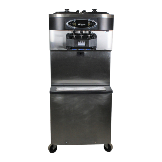
Taylor C713 Original Operating Instructions
Soft serve freezer
Hide thumbs
Also See for C713:
- Service manual (106 pages) ,
- Service manual (120 pages) ,
- Operator training (46 pages)

Related Manuals for Taylor C713


Summary of Contents for Taylor C713
- Page 1 Model C713 Soft Serve Freezer Original Operating Instructions 062180- -M 2/11/05 (Original Publication) (Updated 2/10/12)
- Page 2 Minimum Wire Ampacity: E February, 2005 Taylor All rights reserved. 062180--M Taylor Company The word Taylor and the Crown design 750 N. Blackhawk Blvd. are registered trademarks in the United States Rockton, IL 61072 of America and certain other countries.
-
Page 3: Table Of Contents
....... Model C713 ............ - Page 4 E February, 2005 Taylor (Original Publication) (Updated February, 2012) All rights reserved. 062180--M Taylor Company The word Taylor and the Crown design 750 N. Blackhawk Blvd. are registered trademarks in the United States Rockton, IL 61072 of America and certain other countries.
-
Page 5: To The Installer
Please contact your local authorities if you have any questions. The Model C713 air cooled unit requires a minimum of 3” (76 mm) of clearance on all sides. Install the Care should be taken to ensure that all basic safety... -
Page 6: Water Connections (Water Cooled Units Only)
Refer to the wiring diagram provided cord anchorage to relieve conductors from strain, inside of the electrical box for proper power including twisting, at the terminals and protect the connections. insulation of the conductors from abrasion. To the Installer Model C713... -
Page 7: Beater Rotation
To correct the rotation on a three-phase unit, interchange any two incoming power supply lines at Taylor reminds technicians to be cautious of freezer main terminal block only. government laws regarding refrigerant recovery, To correct rotation on a single-phase unit, change recycling, and reclaiming systems. -
Page 8: To The Operator
Taylor parts, purchased from an technician he employs. authorized Taylor Distributor, and the required It should also be noted that Taylor does not warrant service work is provided by an authorized Taylor the refrigerant used in its equipment. For example, if service technician. -
Page 9: Safety
We, at Taylor Company, are concerned about the safety of the operator when he or she comes in contact with the freezer and its parts. Taylor has gone to extreme efforts to design and manufacture built-in safety features to protect both you and the DO NOT operate the freezer unless it is service technician. - Page 10 Protective gloves must be worn and the mounting holes must NOT be used to lift or hold the dispenser. Failure to follow this instruction can result in personal injury to fingers or equipment damage. Safety Model C713...
-
Page 11: Operator Parts Identification
Section 4 Operator Parts Identification Model C713 Figure 1 111115 Model C713 Operator Parts Identification... - Page 12 C713 Exploded View Parts Identification ITEM DESCRIPTION PART NO. ITEM DESCRIPTION PART NO. COVER-HOPPER 053809-1 CASTER-4” SWV 3/4-10 STEM 044106 ORIFICE 022465-100 SCREW-1/4-20 X 3/8 RHM-SS 011694 O-RING-3/8 OD X ..070 W 016137 PANEL-CORNER-FRONT 063087 RIGHT TUBE A.-FEED-SS 5/32 HOLE X29429-2 CASTER-4”...
-
Page 13: Door And Beater Assembly
Model C713 Door and Beater Assembly Figure 2 ITEM DESCRIPTION PART NO. ITEM DESCRIPTION PART NO. HANDLE A.-DRAW-WELDED X56421-1 CAP-DESIGN 1.010" ID - 6 PT 014218 O-RING-1/4 OD X .070W 50 015872 SEAL-DRAW VALVE 034698 SCREW-ADJUSTMENT-5/16-24 056332 O-RING-7/8 OD X .103 W... -
Page 14: Accessories
PAIL-MIX 10 QT 013163 Not Shown Note: A sample container of sanitizer is sent with the unit. For reorders, order Stera Sheen part no. 055492 (100 2 oz. packs) or Kay-5 part no. 041082 (200 packs). 110516 Operator Parts Identification Model C713... -
Page 15: Brushes
DESCRIPTION PART NO. BLACK BRISTLE BRUSH 013071 BRUSH-END-DOOR SPOUT SS 039719 DOUBLE END BRUSH 013072 BRUSH-SET LVB 050103 WHITE BRISTLE BRUSH 013073 BRUSH-PUMP SPOUT 054068 (1” x 2”) WHITE BRISTLE BRUSH 023316 (3” x 7”) Model C713 Operator Parts Identification... -
Page 16: Important: To The Operator
Important: To the Operator Figure 5 ITEM DESCRIPTION ITEM DESCRIPTION POWER SWITCH MIX LOW INDICATOR LIQUID CRYSTAL DISPLAY SELECT KEY KEYPADS SERVICE MENU KEY MIX OUT INDICATOR BRUSH CLEAN COUNTER STANDBY KEY ARROW KEYS Important: To the Operator Model C713... -
Page 17: Symbol Definitions
To better communicate in the International arena, allows control panel operation. symbols have replaced words on many of our operator switches, function, and fault indicators. Your Taylor equipment is designed with these Fluorescent Display International symbols. The fluorescent display is located on the front control panel. - Page 18 If the air into the freezing cylinder. The air orifice freezer shuts down again, contact your authorized maintains overrun and allows enough mix to enter service technician. the freezing cylinder after a draw. Important: To the Operator Model C713...
-
Page 19: Operating Screen Descriptions
UNIT CLEANED alarm will be on. If the system detects corrupt data during INITIALIZING, the following display will alert the operator that the control settings may have been changed (See Figure 8.) Figure 11 Model C713 Important: To the Operator... -
Page 20: Manager's Menu
Note: The machine will continue operation in the mode it was in when the menu was selected. However, the control keys will not be lit and are non-functional when the Manager's Menu is displayed. Figure 14 Important: To the Operator Model C713... - Page 21 Exit to Change, then touch brush cleaned. (See Figure 15.) the SEL symbol to select the Change option. (See Figure 18.) SERVINGS COUNTER SET CLOCK 12:01 7/15/2004 Change > Next > Exit Figure 15 Figure 18 050722 Model C713 Important: To the Operator...
- Page 22 AUTO Manager's Menu and select the AUTO mode. mode manually. (See Figure 21.) (See Figure 24.) AUTO START TIME STANDBY MODE DISABLED Enable > Disable > EXIT Figure 21 Figure 24 Important: To the Operator Model C713...
- Page 23 Note: Refer to your local health codes regarding backward to view each screen. The following list temperature recommendations for procedures to indicates the variable messages that may appear. follow if these fault screens appear. Model C713 Important: To the Operator...
- Page 24 Touching the machine. (See Figure 27.) SEL symbol again will return to the Menu list. (See Figure 29.) SOFTWARE VERSION C713 CONTROL UVC3 B.O.M. C71333C000 VERSION 1.04 K0000000 > Next > Next...
-
Page 25: Operating Procedures
Section 6 Operating Procedures The C713 machine stores mix in the hoppers. It has Step 3 two 3.4 quart (3.2 liter) capacity freezing cylinders Heavily lubricate the inside portion of the boot seal with a three spout door. Mix flows by gravity through and also lubricate the flat end of the boot seal that a feed tube down into the freezing cylinders. - Page 26 Slide the front bearings over the baffle rods. Figure 33 The flanged edges should be against the door. DO Repeat this step for the second scraper blade. NOT lubricate the gaskets or bearings. Operating Procedures Model C713...
- Page 27 Step 13 Slide the two o-rings into the grooves on each prime To install the freezer door, insert the baffle rods plug. Apply an even coat of Taylor Lube to the through the beaters in the freezing cylinders. o-rings and shafts.
- Page 28 Step 15 Lubricate the inside of the freezer door spouts, top and bottom. Figure 42 Step 18 Slide the pivot pin through each draw handle as they Figure 40 are inserted into the draw valves. Figure 43 Operating Procedures Model C713...
- Page 29 Figure 47 Slide the two drip pans into the holes in the side panels. Step 23 Slide the small o-ring into the groove of the air orifice. Do not lubricate the o-ring. Figure 45 Figure 48 Model C713 Operating Procedures...
-
Page 30: Sanitizing
Pour the sanitizing solution over all the parts in the Kay-5R or 2 gal. [7.6 liters] of Stera-SheenR). bottom of the mix hopper and allow it to flow into the USE WARM WATER AND FOLLOW THE MANU- freezing cylinder. FACTURER'S SPECIFICATIONS. Operating Procedures Model C713... -
Page 31: Priming
Stand the feed tube in the hopper cover in position. corner of the hopper. Step 13 Step 7 Repeat these steps for the other side of the Repeat these steps for the other side of the machine. machine. Model C713 Operating Procedures... -
Page 32: Manual Brush Cleaning
Pour two gallons (7.6 liters) of cool, clean water into the mix hopper. With the white hopper brush, scrub the mix hopper and the mix level sensing probe. To disassemble the Model C713, the following items Using the double ended brush, brush clean the mix will be needed: inlet hole. -
Page 33: Hopper Cleaning
Note: If the drip pans are filled with an excessive amount of mix, it is an indication that the drive shaft Repeat these steps on the other side of the seal(s), or o-ring(s) should be replaced or properly machine. lubricated. Model C713 Operating Procedures... -
Page 34: Brush Cleaning
Return to the freezer with a small amount of cleaning solution. Using the black brush, clean the Step 5 rear shell bearing at the back of the freezing Wipe all exterior surfaces of the freezer with a clean, cylinder. sanitized towel. Operating Procedures Model C713... -
Page 35: Important: Operator Checklist
Be sure there is a rear shell bearing and the female hex drive generous amount of cleaning solution on the socket clean and free of lubricant and mix brush. deposits. 120210 Model C713 Important: Operator Checklist... -
Page 36: Winter Storage
Your local Taylor Distributor can perform this winter storage service for you. Caution: Always disconnect Wrap detachable parts of the freezer such as... -
Page 37: Troubleshooting Guide
The viscosity control is set b. Call an authorized service - - - technician. too cold. c. Freeze-up in mix inlet c. Call an authorized service - - - technician. hole. Model C713 Important: Operator Checklist... - Page 38 Rounded corners of drive b. Call an authorized service - - - technician. shaft, drive coupling, or both. - - - c. Gear box is out of c. Call an authorized service technician. alignment. Important: Operator Checklist Model C713...
- Page 39 Machine is unplugged. a. Plug into wall receptacle. - - - with power switch ON. b. Circuit breaker OFF or b. Turn the breaker ON or - - - replace the fuse. blown fuse. Model C713 Important: Operator Checklist...
-
Page 40: Parts Replacement Schedule
Minimum if Necessary White Bristle Brush, 1” x 2” Inspect & Replace Minimum if Necessary Black Bristle Brush, 1” x 2” Inspect & Replace Minimum if Necessary Double-Ended Brush Inspect & Replace Minimum if Necessary Parts Replacement Schedule Model C713... -
Page 41: Parts List
Section 10 Parts List 100902 Model C713 Parts List... - Page 42 Parts List Model C713...
- Page 43 Model C713 Parts List...
- Page 44 Parts List Model C713...
- Page 45 Model C713 Parts List...
- Page 46 Parts List Model C713...
- Page 47 100930 Model C713 Parts List...
- Page 48 Parts List Model C713...
- Page 49 Model C713 059899-27 7/25/11...
- Page 50 Model C713 059899-33 7/25/11...
- Page 51 Model C713 059899-40 7/25/11...
- Page 52 Model C713 059899-58 7/25/11...
Need help?
Do you have a question about the C713 and is the answer not in the manual?
Questions and answers