Table of Contents
Advertisement
Quick Links
Advertisement
Table of Contents

Related Manuals for Avid Technology HD OMNI


Summary of Contents for Avid Technology HD OMNI
- Page 1 HD OMNI Guide...
- Page 2 Legal Notices This guide is copyrighted ©2011 by Avid Technology, Inc., (hereafter “Avid”), with all rights reserved. Under copyright laws, this guide may not be duplicated in whole or in part without the written consent of Avid. 003, 96 I/O, 96i I/O, 192 Digital I/O, 192 I/O, 888|24 I/O,...
-
Page 3: Table Of Contents
Chapter 4. Configuring HD OMNI in Pro Tools ....... . . - Page 4 ............63 Safety Compliance HD OMNI Guide...
-
Page 5: Chapter 1. Introduction
Chapter 1: Introduction ® Avid HD OMNI is a professional digital audio • Soft Clip and Curv limiting circuits to protect interface designed for use with Avid HD Native against clipping on analog input and Pro Tools|HD hardware. HD OMNI provides •... -
Page 6: What's Included
• External Clock input and output for synchro- • Technical support information nizing HD OMNI with external Word Clock • Software update and upgrade notices devices • Hardware warranty information Hardware Warranty What’s Included... -
Page 7: About This Guide
About This Guide All of our guides use the following conventions This guide provides a basic overview of the to indicate menu choices and key commands: HD OMNI features and functionality. Convention Action For hardware installation instructions for your HD Native hardware, see the HD Native Install File >... -
Page 8: About Www.avid.com
Products and Developers products; download demo software or learn about our Development Partners and their plug- ins, applications, and hardware. Get the latest news from Avid News and Events or sign up for a Pro Tools demo. HD OMNI Guide... -
Page 9: Chapter 2. Hd Omni Overview
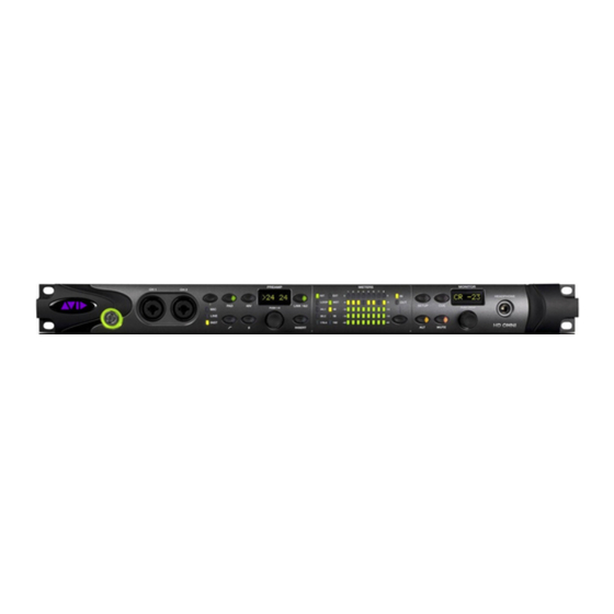
Chapter 2: HD OMNI Overview This chapter provides an overview of the front and back panel features of HD OMNI. HD OMNI Front Panel HD OMNI Front Panel Power Switch and LED Ring CH1 and CH2 Inputs This button turns HD OMNI on and off. -
Page 10: Preamp Controls
(or disabled) on Channels 1 and 2 by pressing the PREAMP Encoder to select the desired channel. Inserting or removing an XLR cable to or from the front panel inputs automatically disables phantom power (if it is on). HD OMNI Guide... - Page 11 Channel 2). Turn the encoder clockwise to increase and counterclockwise to decrease the input gain for the selected channel (from +10 to +65 dB). Gain can be adjusted in 1 dB incre- ments. Chapter 2: HD OMNI Overview...
- Page 12 Clock Source as set in the Pro Tools Hardware Setup (see “Pro Tools Hardware Setup” on The Word Clock base rate can only be set in page 25) or on HD OMNI in SETUP mode (see the Pro Tools Hardware Setup. “Clock Source (CLOCK)” on page 50).
- Page 13 Output channels as- signed in the Pro Tools Hardware Setup. A signal that meters at 0 on the HD OMNI will not necessarily clip; use the on-screen meters in Pro Tools to determine whether a signal is clipping.
- Page 14 Trim values in ALT Trim mode For more information on configuring moni- and to navigate Setup mode. Press the encoder toring with HD OMNI in Pro Tools, see to switch between Control Room (CR) and “Monitor” on page 29.
- Page 15 Use the MONITOR Encoder to control the Head- phone level (see“MONITOR Controls” on page 10). The HD OMNI Headphone output also lets you monitor greater than stereo format sessions, in two different ways: passing the Left and Right channels only, or folding down from the greater-than-stereo format to stereo.
-
Page 16: Hd Omni Back Panel
HD OMNI Back Panel Analog Inputs SEND and RTN 1 and 2 HD OMNI provides up to four channels of simul- HD OMNI provides two discrete hardware sends taneous analog inputs to Pro Tools using 24-bit and returns. The selected inputs (MIC, LINE, or... -
Page 17: Analog Outputs
Single Wire mode. Hardware Setup dialog (see “Analog Out” on For a pinout diagram for the AES/EBU DB- page 28) or on HD OMNI in SETUP mode (see 25 connector, see Chapter , “Pinout Dia- “TRS Output Mirrors (TRSOUT)” on page 47) grams for the DB-25 Connectors.”... - Page 18 Optical (S/PDIF) Optical (TOSLINK) input and output. The Opti- Pro Tools Hardware Setup dialog. cal I/O on HD OMNI supports up to 24-bit au- dio, at sample rates up to 192 kHz. The number About Lightpipe-Compatible Devices of available Optical input and output channels...
- Page 19 Use a DigiLink cable with a DigiLink Mini The EXPANSION PORT lets you connect an ad- adapter to connect HD OMNI to a Pro Tools|HD ditional Avid HD audio interface to HD OMNI. card, as well as to legacy Pro Tools|HD audio in- The EXPANSION PORT passes input and output terfaces (such as 192 I/O).
- Page 20 SYNC HD or SYNC I/O). AC Power This connector accepts a standard AC power ca- ble (included). HD OMNI is auto power-select- ing (100V to 240V) and will automatically work with a standard modular cable (IEC) to connect to AC power outlets in any country.
-
Page 21: Chapter 3. Connecting Hd Omni
Chapter 3: Connecting HD OMNI Studio Connections HD OMNI provides up to eight channels of ana- log and digital I/O (4 in and 8 out), a compact HD OMNI can be integrated with your other preamp, input mixer, monitoring, and I/O solu-... -
Page 22: Connecting Hd Omni To An Hd Native Card
Connecting HD OMNI to an HD Native Card You can use up to eight channels of analog and digital I/O (4 in and 8 out) with HD OMNI connected to an HD Native card using a DigiLink Mini cable. To connect HD OMNI to an HD Native card, do one of the following: Connect HD OMNI Primary Port to DigiLink Mini Port 1 on the HD Native card with a DigiLink ... - Page 23 Connect the Loop Sync Out of the last interface to the Loop Sync In of the primary interface with a BNC cable. HD Native card Figure 2. DigiLink Mini and Loop Sync connections for an HD OMNI and three HD I/Os with HD Native Chapter 3: Connecting HD OMNI...
-
Page 24: Connecting Hd Omni To Pro Tools|Hd Cards
Connecting HD OMNI to Pro Tools|HD Cards You can use up to eight channels of analog and digital I/O (4 in and 8 out) with HD OMNI connected to a Pro Tools|HD card using a DigiLink Mini cable with a DigiLink Mini adapter. - Page 25 Connect the Loop Sync Out of the last interface to the Loop Sync In of the primary interface or SYNC peripheral with a BNC cable. Pro Tools|HD Accel Core card Pro Tools|HD Accel card Figure 4. DigiLink and Loop Sync connections with two Pro Tools|HD cards, one HD OMNI, and three HD I/Os Chapter 3: Connecting HD OMNI...
-
Page 26: Example Studio Connections
OMNI. Note that the line level inputs are only available on the back panel. HD OMNI provides DB-25 breakout connectors for analog and AES/EBU output. Avid sells several different DigiSnake DB-25 cables for these purposes. For more information, contact your dealer or visit the Avid Store online at our website (www.avid.com). - Page 27 Optical in/out to ADAT Digital Inputs/Outputs Analog to DAT recorder Output Hardware Inserts Power Amp and Speakers Figure 6. Example studio configuration using HD OMNI, back panel connections shown Chapter 3: Connecting HD OMNI...
- Page 28 HD OMNI Guide...
-
Page 29: Chapter 4. Configuring Hd Omni In Pro Tools
Click the tab and configure the op- Analog Out tions (see “Analog Out” on page 28). as in Setup mode on HD OMNI (see Chapter 5, “SETUP Mode”). Click the tab and configure the options Mixer (see “Mixer”... - Page 30 Pro Tools to external clock sources. “Monitor” sound through the corresponding Depending on the selected Digital 1–2 Input physical outputs). Format, Clock Source options include: Internal The HD OMNI Mute button and Monitor AES/EBU S/PDIF Optical (S/PDIF) ADAT 1–8 encoder (used for adjusting the Control (at 44.1 kHz and 48 kHz),...
- Page 31 • S/PDIF fers from the Pro Tools session sample rate, • Optical (S/PDIF)—resets the Optical I/O HD OMNI converts the incoming sample rate to port (which is, by default, eight channels of the session sample rate in real time. ADAT I/O) to two channels of...
- Page 32 Reference Level for the phys- with large overloads on input. ical analog inputs on HD OMNI. You can also ap- ply a limiter to each of the four analog inputs. Analog Out...
- Page 33 The TRS OUT 1 and 2 jacks on the back panel of ware Setup dialog, the Output and Bus pages of HD OMNI can mirror the analog signal output of the I/O Setup dialog, and in the Output path channels 1–2 or 7–8. Select the appropriate op- names for tracks in your Pro Tools session.
- Page 34 Place the mouse cursor over the Channel Ma- trix (the cursor appears as a pencil), and click to assign Control Room Path monitoring channels to physical output channels on HD OMNI. These appear as Output channels for Pro Tools tracks. Assigning Control Room Path monitoring channels to...
- Page 35 Monitor path (see 2. below). Stereo Monitor path assigned to Analog 1 and 5 as it appears in the Hardware Setup (1 & 2) and in the I/O Setup (3) Chapter 4: Configuring HD OMNI in Pro Tools...
- Page 36 CR Path A Note About Odd Number Formats The Control Room Path (CR Path) channel ma- Since the Output channels for HD OMNI are in trix provides monitoring channel assignment stereo pairs, any time you assign an odd num- rows for the MAIN and ALT CR Path.
- Page 37 Pro Tools sends only two output channels (ste- selectors let you select any channel format that reo) to HD OMNI. The LFE channel, or .1 chan- is narrower than the channel format selected for nel, is synthesized on the HD OMNI rather than the corresponding CR Path.
- Page 38 I/O Setup, indicating they are in use Note that any signal routed to the “Monitor” and unavailable for other output assignments. path from Pro Tools tracks plays out the corre- sponding assigned physical output according to the MAIN and ALT assignments. HD OMNI Guide...
- Page 39 HD OMNI provides intelligent fold down op- tions for the MAIN and ALT Control Room, and headphone monitoring paths. HD OMNI provides three types of fold down op- tions: Fold down between formats of the same Type 1 monitor path. For example, fold down the MAIN...
- Page 40 CR Paths Select Do Not Fold Down (L/R Channels Only) of HD OMNI folds down the 5.1 MAIN CR Path this option to not fold down from a greater- to the Stereo ALT CR Path. than-stereo CR Path and only pass the Left and Right channels for headphone monitoring.
- Page 41 The Mixer page of the Hardware Setup dialog The Mixer channel strips are grouped in pairs of lets you configure HD OMNI to mix the signals physical outputs: Analog 1–2, Analog 3–4, coming from HD OMNI physical inputs to the AES/EBU, ADAT 1–2, and so on.
- Page 42 Volume control to set it to the default have audio playing through Analog 1–2 using unity setting. the HD OMNI Mixer, and you have a stereo track Mutes (or unmutes) the input sig- Mute Button in Pro Tools that has Analog 1–2 set as the track nal to all selected output assignments.
-
Page 43: Pro Tools I/O Setup
This section describes how to configure input, Click output, bus, monitoring, cue, and other signal paths for HD OMNI in the Pro Tools I/O Setup. When you click , Pro Tools checks several settings for routing validity (to prevent feed- For more information the I/O Setup dialog, back loops). - Page 44 Output output ports in the I/O Setup are linked to the eight channels of physical outputs selected for The Output page of the I/O Setup for HD OMNI in the Main page of the Hardware Setup. Output lets you configure output signal path names and If you change the setting on one dialog, it auto- formats.
- Page 45 To assign HD OMNI physical outputs to Pro Tools 1–6 are automatically assigned to Monitor 1–2, Output paths, do one of the following: Monitor 3–4, and Monitor 5–6. In the Output Channel Mapping grid, the Monitor Path spans On the Output page of the I/O Setup dialog ...
- Page 46 Headphone jack on the front panel able system output channel paths. of HD OMNI. You can assign Pro Tools Output channels (left and right) to CUE 1–2 in the Out- put page in the I/O Setup. Use these Output channels (such as A 9–10) from Pro Tools track...
- Page 47 Hardware Inserts that you may have connected for configuring hardware connections with a to your Pro Tools audio interface. However, PRE (if present). with HD OMNI, any channels that are used for H/W Insert Delays monitoring are unavailable for hardware in- serts.
- Page 48 HD OMNI Guide...
-
Page 49: Chapter 5. Setup Mode
Press the SETUP button on the front panel of • SPL Display Calibration (“SPLCAL”) HD OMNI so that the SETUP button LED is lit. • Fan Control (“FAN”) Also, while in SETUP mode, text in the Display • Firmware Version (“VER”) lights amber. -
Page 50: Analog Output (Outlvl)
Press SETUP button to exit OUTRIM and re- SETUP LED stops blinking and lights solid turn to top level of SETUP Options menu. The green. SETUP LED stops blinking and lights solid green. Exit SETUP mode. Exit SETUP mode. HD OMNI Guide... -
Page 51: Trs Output Mirrors (Trsout)
(TRSOUT) control lets you set whether the Ana- figured in the Hardware Setup in Pro Tools) is log TRS outputs on the back panel of HD OMNI enabled or not for the MAIN and ALT Control mirror DB-25 Outputs 1–2 or DB-25 Outputs Room paths. -
Page 52: Analog Line Input Reference Level (In Ref)
Repeat preceding steps to set the Input Refer- ence Level for Analog Input 2–4. Press SETUP button to exit IN REF and return to top level of SETUP Options menu. The SETUP LED stops blinking and lights solid green. Exit SETUP mode. HD OMNI Guide... -
Page 53: Limiter (Limitr)
(SRATE) control lets you set the internal sample puts. rate for HD OMNI (44.1 kHz to 192 kHz). At sample rates of 176.4 kHz and 192 kHz, Sam- The Limiter control is unavailable in... -
Page 54: Clock Source (Clock)
In SETUP mode, the Digital 1–2 Input Source HD OMNI. (DIG IN) control lets you set the Digital 1–2 In- put Format for HD OMNI. The Clock Source control is unavailable in SETUP mode when Pro Tools is running. The Digital 1–2 Input Source control is un-... -
Page 55: Sample Rate Conversion (Src1-2)
At sample rates of 176.4 kHz and 192 kHz, Sam- is automatically enabled if ple Rate Conversion HD OMNI lets you adjust the SPL Display Cali- is set to Digital 1–2 Input Format Optical bration both for the MAIN and ALT Monitor (S/PDIF) Paths. - Page 56 Press the MONITOR encoder button to con- firm the setting. Exit SETUP mode. Press SETUP button to exit SPLCAL and re- turn to top level of SETUP Options menu. The SETUP LED stops blinking and lights solid green. Exit SETUP mode. HD OMNI Guide...
-
Page 57: Fan Control (Fan)
The fan runs at high or low speed auto- AUTO matically, depending on the internal tempera- ture of HD OMNI. Select this option if HD OMNI is present in your listening environment. Press the MONITOR encoder button to select the displayed FAN option. -
Page 58: Firmware Version (Ver)
Board revision: HD OMNI to the factory settings. Enter SETUP mode. The SETUP LED lights To reset HD OMNI to the factory default settings: green. Enter SETUP mode. The SETUP LED lights Turn the MONITOR encoder until the display green. -
Page 59: Display Contrast (Cntrst)
In SETUP mode, the Display Contrast (CNTRST) control lets you adjust the contrast for the HD OMNI display (0–62). To adjust the contrast for the HD OMNI Display: Enter SETUP mode. The SETUP LED lights green. Turn the MONITOR encoder until the display shows “CNTRST.”... - Page 60 HD OMNI Guide...
-
Page 61: Chapter 6. Pinout Diagrams For The Db-25 Connectors
Chapter 6: Pinout Diagrams for the DB-25 Connectors Analog Output DB-25 AES/EBU DB-25 CH12_RCV_HOT +4" Analog Outputs CH12_RCV_COLD CH12_RCV_GND CH1_HOT CH34_RCV_HOT CH1_COLD CH34_RCV_COLD CH1_GND CH34_RCV_GND CH2_HOT CH56_RCV_HOT CH2_COLD CH56_RCV_COLD CH2_GND CH56_RCV_GND CH3_HOT CH78_RCV_HOT CH3_COLD CH78_RCV_COLD CH3_GND CH78_RCV_GND CH4_HOT CH12_XMT_HOT CH4_COLD CH12_XMT_COLD CH4_GND CH12_XMT_GND... - Page 62 HD OMNI Guide...
-
Page 63: Chapter 7. Sound Pressure Level Display Calibration
Press the MONITOR encoder button to select Unity. the SET. The display changes to show 0SPL. On HD OMNI, set the MAIN CR Path gain to Turn the MONITOR encoder to until the dis- 0 dB using the Monitor encoder. - Page 64 ALT speaker out- puts, instead adjust the ALT Control Room level and calibrate it to match to the refer- ence set for the MAIN CR Path (in our exam- ple 85 SPL). HD OMNI Guide...
-
Page 65: Appendix A. Compliance Information
Appendix A: Compliance Information Proposition 65 Warning Environmental Compliance This product contains chemicals, including lead, Disposal of Waste Equipment by Users known to the State of California to cause cancer and in the European Union birth defects or other reproductive harm. Wash hands after handling. -
Page 66: Emc (Electromagnetic Compliance)
Any modifications to the unit, unless expressly approved by mark on this compliant equipment thereby declaring Avid, could void the user's authority to operate the conformity to EMC Directive 2004/108/EC and Low Voltage equipment. Directive 2006/95/EC. Argentina Conformity Korean EMC Regulations HD OMNI Guide... -
Page 67: Safety Compliance
The main power switch is located on the front panel of the 5) Do not use this equipment near water. HD OMNI. It should remain accessible after installation. 6) Clean only with dry cloth. 18) The equipment shall be used at a maximum ambient temperature of 40°... - Page 68 HD OMNI Guide...
- Page 70 Avid Technical Support (USA) Product Information 2001 Junipero Serra Boulevard Visit the Online Support Center at For company and product information, Daly City, CA 94014-3886 USA www.avid.com/support visit us on the web at www.avid.com...
Need help?
Do you have a question about the HD OMNI and is the answer not in the manual?
Questions and answers