Table of Contents
Advertisement
Quick Links
Advertisement
Table of Contents

Related Manuals for Avid Technology DigiDesign PRE


Summary of Contents for Avid Technology DigiDesign PRE
- Page 1 ® ™ Pro Tools | PRE Guide...
- Page 2 Legal Notices Sundance Digital, SurroundScope, Symphony, SYNC HD, SYNC I/O, Synchronic, SynchroScope, Syntax, © 2014 Avid Technology, Inc., (“Avid”), all rights reserved. TDM FlexCable, TechFlix, Tel-Ray, Thunder, TimeLiner, This guide may not be duplicated in whole or in part without Titansync, Titan, TL Aggro, TL AutoPan, TL Drum Rehab, the written consent of Avid.
-
Page 3: Table Of Contents
Contents Chapter 1. Introduction ............1 . - Page 4 Chapter 4. Specifications ............29 Chapter 5.
- Page 5 Chapter 10. 仕様 ............. . 33 Pro Tools | PRE DB-25 の...
- Page 6 Pro Tools | PRE Guide...
-
Page 7: Chapter 1. Introduction
Chapter 1: Introduction Pro Tools | PRE™ is designed especially for use • +48V power for condenser microphones ® with Pro Tools systems, but it can also be used as • Balanced Insert points (Send and Return), for a stand-alone microphone preamplifier. When easy integration of outboard gear (such as used with Pro Tools, most PRE features can be compressors or EQs) -
Page 8: System Requirements And Compatibility Information
System Requirements and Conventions Used in This Compatibility Information Guide When used as a stand-alone microphone preampli- All of our guides use the following conventions to fier, PRE is ready to use. indicate menu choices and key commands: For remote control within Pro Tools, PRE Convention Action requires a qualified Pro Tools system. -
Page 9: About Www.avid.com
About www.avid.com The Avid website (www.avid.com) is your best online source for information to help you get the most out of your Pro Tools system. The following are just a few of the services and features available. Register your purchase Product Registration online. - Page 10 Pro Tools | PRE Guide...
-
Page 11: Chapter 2. Hardware Overview And Stand-Alone Operation
Chapter 2: Hardware Overview and Stand- Alone Operation This chapter describes the Pro Tools | PRE front and back panels, and includes instructions for using its switches, indicators, and connectors for Stand-alone mode operation. To use PRE in Remote mode (remote control of PRE by Pro Tools or a dedicated control surface), see Chapter 3, “Remote Operation.”... - Page 12 Remote “Lock-Out” LED The PRE oscillator signal can be routed through the OSC output on the back of the unit or through When lit (green), this LED indicates PRE is in Re- individual channels on the DB-25 connector. mote Lock-Out mode. In this mode, PRE is con- nected to a remote controller (such as Pro Tools or To route the signal to the OSC output: a dedicated device), and the front panel controls...
- Page 13 Gain/Param Display Clear Clips Switch This three-character, seven-segment LED displays This switch clears Clip indicators on the Peak me- the input gain for the currently selected PRE chan- ter and Signal indicators. nel, or the PRE’s MIDI channel. Peak Hold Switch and LEDs This display can also show the current firmware This switch sets the clip hold action of the SIG me- version of PRE.
- Page 14 Input Impedance (Represented as Z) When clipping occurs, the LED remains lit or clears, depending on the Peak Hold setting. Clips The Input Z switch sets the input impedance for a can also be manually cleared with the Clear Clip PRE channel to 1.5 k, 15 k, or 1.5 M.
- Page 15 Insert Switch and LEDs Channel Select Switches and LEDs This switch enables insert points on individual These switches are used to focus one or more chan- channels. When lit (yellow), Insert LEDs indicate nels to adjust their controls. When lit (green), the which channels have their insert point enabled.
-
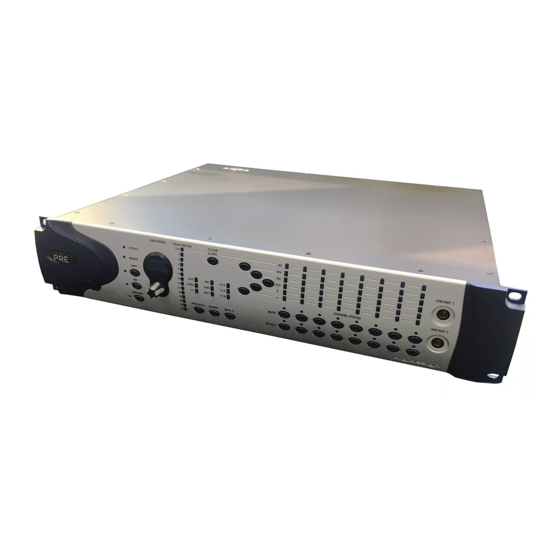
Page 16: Pro Tools | Pre Back Panel
Pro Tools | PRE Back Panel Pro Tools | PRE has the following back panel connectors: Mic Inputs 1–8 Line/Inst Inputs 1–8 Oscillator Output Power supply Output Trims 1–8 Send and Return Inserts 1–8 DB-25 Outputs 1–8 MIDI In/Out/Thru connector Pro Tools | PRE back panel Mic Inputs 1–8 DB-25 Outputs 1–8... - Page 17 Output Trims 1–8 Oscillator (OSC) Output The output trims are used to individually calibrate This is a balanced 1/4-inch TRS jack that outputs a each channel’s output and send level. fixed oscillator signal (+4 dBu reference signal at approximately 1 kHz) for calibrating the inputs of The output trims are factory-calibrated so that the gear not connected through the DB-25 output.
-
Page 18: Using Pro Tools | Pre In Stand-Alone Mode
Verify that phantom power (48V) is disabled. Using Pro Tools | PRE in Press the 48V switch so that the 48V LED is off. Stand-Alone Mode Although phantom power (48V) can be used PRE can be used without Pro Tools as a stand- safely with most microphones, some ribbon alone microphone preamplifier. -
Page 19: Calibrating Pro Tools | Pre And Other Devices
The output trims are factory-calibrated so that the If using line inputs with balanced line level clip point of the PRE output amplifier matches the devices, be sure to use balanced to balanced factory-set clip point of HD I/O and 192 I/O ana- cables to maximize performance. -
Page 20: Adjusting Input Gain
To change a setting with a channel control switch: Adjusting Input Gain Select one or more channels. To set input gain on a channel: Press a channel control switch to change its cur- rent setting. For example, if the 48V LED is off, If the Gain/Param display currently shows a pressing 48V will enable 48V phantom power MIDI channel, press MIDI. -
Page 21: Chapter 3. Remote Operation
Chapter 3: Remote Operation Installation of PRE remote control in Pro Tools PRE Remote Control in Pro Tools includes: The following PRE front panel controls can be re- • Making audio and MIDI connections to PRE motely controlled in Pro Tools: (See “Connecting Pro Tools | PRE to a •... -
Page 22: Connecting Pro Tools | Pre To A Pro Tools System
MIDI Connections Connecting Pro Tools | PRE to a Pro Tools System The following are basic instructions for connecting your PRE to a MIDI interface for remote control. Audio Connections Before you connect PRE MIDI Ins and Outs, con- nect and configure your MIDI interface according PRE must be physically connected to an audio in- to the manufacturer’s instructions. - Page 23 Powering Up a Pro Tools System Setting the PRE MIDI Channel In order for Pro Tools to communicate properly To set the global receive/transmit MIDI channel: with audio interfaces and other peripherals, it is On the PRE front panel, press the MIDI Chan important that you start up and shut down your sys- switch so the LED lights.
-
Page 24: Configuring Midi Studio In Ams For Pro Tools | Pre
Enable the appropriate Channels for the Trans- Configuring MIDI Studio in options. mits Receives AMS for Pro Tools | PRE Click and close the Properties window. Apply (Mac Only) Connect the PRE icon to the correct port on the The following are basic instructions for configur- MIDI interface icon: ing PRE in the Apple Audio MIDI Setup applica- •... -
Page 25: Configuring Midi Studio Setup For Pro Tools | Pre
Configuring MIDI Studio Configuring Pro Tools Setup for Pro Tools | PRE Software for Pro Tools | PRE (Windows Only) Once PRE has been configured in AMS or MSS, it can be declared in the Pro Tools Peripherals dialog The following are basic instructions for configur- and mapped in the I/O Setup dialog, in order to es- ing PRE in MIDI Studio Setup (MSS). - Page 26 Click Reset to return PRE parameters to From the pop-up menu, choose the Reset Send To their defaults. Resetting takes place immediately; destination port for the connected PRE and you do not need to click OK to reset parameters. MIDI channel to transmit data. Again, be sure you choose the correct MIDI channel in multi- Select this option to re- Retain Current Settings...
- Page 27 to, the PRE controls (identified as Mic Preamps) To map channels: appear on top of the channel strip, giving you audio Choose and click the Setup > I/O Mic Preamps and control. Make sure that Display > Mix Windows tab. Shows >...
- Page 28 Channel Shuffling • Select multiple PRE paths by Shift-clicking the desired path names. If the destination channel is already occupied, Click moving a signal from right to left results in a shuf- Default fle of other signals after the new destination chan- Active and Inactive Paths nel.
-
Page 29: Mic Preamps In Pro Tools Edit And Mix Windows
Mic Preamp Paths Mic Preamps in Pro Tools Edit and Mix Windows When audio tracks or Auxiliary Inputs are created, their mono, stereo, or multichannel format is de- After you create a new track and set the track input fined. This format determines the Mic Preamp be- to an analog input that the PRE output channel is havior. -
Page 30: Viewing Mic Preamp Controls In Pro Tools
Viewing Mic Preamp Controls Mic Preamp Controls in Pro Tools The Mic Preamps view provides all the essential controls for a PRE channel in the Mix and Edit windows. Source and Mic Pre window Impedance Source and Input Impedance Selector Phase Clicking the up/down arrows in the Mic Preamp Insert... -
Page 31: Mic Preamp Window
Pad Button and LED Mic Preamp Window This button applies an input pad to individual The Mic Preamp window provides all the essential channels to reduce input sensitivity by 18 dB. PRE controls, plus a gain fader and access to the Insert Button channel strip Input Selector, as an alternative to Mix and Edit window views. - Page 32 Mic Preamp Window Controls Standard Controls Mic Preamp windows provide standard selectors Refer to “Mic Preamp Controls” on page 24 for a for PRE controls and other controls in the top area description of Mic Preamp view controls that are of the window.
-
Page 33: Adjusting Mic Preamp Controls
Adjusting Mic Preamp Mic Preamp Remote Control Controls with Control Surfaces Pro Tools systems configured with PRE remote To adjust a control on a single channel: control and a supported control surface can use the Choose View > Mix Window Views > Mic Pre- control surface to control one or more Mic Pre- amps amps in Pro Tools. - Page 34 Pro Tools | PRE Guide...
-
Page 35: Chapter 4. Specifications
Chapter 4: Specifications 0 dB to +69 dB, in approximately Gain Range 3 dB steps. With Pad enabled, –18 to +51 dB. 1.5k ohm (low imped- Input Impedance (Input Z): ance); 15k ohm (mid impedance); 1.5M ohm (high impedance) Frequency Response: ±0.1 dB;... - Page 36 Pro Tools | PRE Guide...
-
Page 37: Chapter 5. Pinout Diagram For The Pre Db-25 Connector
Chapter 5: Pinout Diagram for the PRE DB-25 Connector DB-25 Connector Figure 1. DB-25 Connector pinouts Chapter 5: Pinout Diagram for the PRE DB-25 Connector... - Page 38 Pro Tools | PRE Guide...
-
Page 39: Chapter 6. Midi Controller Numbers
Chapter 6: MIDI Controller Numbers If you do not have a Pro Tools Control Surface, All values are in hexadecimal format and may need you can use a third-party MIDI control surface to to be converted to decimal for some MIDI devices. control PRE in Pro Tools. - Page 40 Table 7. PRE MIDI Implementation Table 7. PRE MIDI Implementation Name Name Channel Channel Insert 00h=out, Insert 00h=out, 7Fh=in 7Fh=in 00h=off, 00h=off, 7Fh=on 7Fh=on Phase 00h=off, Phase 00h=off, 7Fh=on 7Fh=on High-Pass Filter 2 00h=out, High-Pass Filter 4 00h=out, 7Fh=in 7Fh=in Mute 00h=off, Mute...
- Page 41 Table 7. PRE MIDI Implementation Table 7. PRE MIDI Implementation Name Name Channel Channel Insert 00h=out, Insert 00h=out, 7Fh=in 7Fh=in 00h=off, 00h=off, 7Fh=on 7Fh=on Phase 00h=off, Phase 00h=off, 7Fh=on 7Fh=on High-Pass Filter 6 00h=out, High-Pass Filter 8 00h=out, 7Fh=in 7Fh=in Mute 00h=off, Mute...
- Page 42 PRE Gain Step Table Table 8. PRE Gain Steps Table 8. PRE Gain Steps Step Level dB Step Level dB Pro Tools | PRE Guide...
-
Page 43: Chapter 7. はじめに
第 章: はじめに は システム 各チャンネルの特徴: Pro Tools | PRE Pro Tools® • と共に使用するよう設計されていますが、 マイクロフォン( )、ライン・レ • スタンドアロンのマイク・プリアンプとし ベル・インプット( インチ) 、楽器 て使用することもできます。 と Pro Tools ( インチ)への対応 共に使用する場合は、 のほとんどの機 マイク ・ インプットのインピーダンスの設 • 能は アプリケーション内から操 Pro Tools 定が選択可 作できます。 インプット ・ ゲインを 〜... -
Page 44: システムの必要条件と互換性情報
システムの必要条件と互換性情報 本ガイドで使用する表記法 は そ の ま ま ス タ ン ド ア ロ ン の マ イ ク 弊社のすべてのガイドは、メニューの選択 プリアンプとして使うことができます。 肢とキー・コマンドを示すため、以下の表 記法を使用しています: からリモート・コントロールす Pro Tools るには、要件を満たした システ Pro Tools ムが必要です。 File > は、 動作確認が行われたハードウェア Avid Save とソフトウェアに対してのみ互換性を保証 Control+N Control し、サポートを提供します。 完全なシステム要件および要件を満たした... -
Page 45: Www.avid.com
www.avid.com について のウェブサイトは、 システ Avid Pro Tools ムを最大限に活用するための最良のオンラ イン情報源です。以下はそのサービスと機 能の一例です。 購入した製品をオンラインで登録 できます。 カスタマー・サ Avid クセス(テクニカル・サポート)にアクセ スすると、ソフトウェアのアップデートや 最新版のオンライン・マニュアルのダウン ロード、システム要件のための互換性ガイ ドの参照、オンライン・ナレッジベースの検 索、そして世界規模の ユーザー・ Pro Tools コミュニティへの参加が可能です。 オンラインで利用可能な コースを通じて自己学習したり、認定された トレーニング・センターが提供す Pro Tools るコース内容を確認したりすることができ ます。 製品に関する情報、ソフ Avid ト ウ ェ ア の デ モ 版 の ダ ウ ン ロ ー ド、開 発 パートナーとそのプラグイン、アプリケー... - Page 46 Pro Tools | PRE...
-
Page 47: Chapter 8. ハードウェアの概要とスタンドアロン操作
第 章: ハードウェアの概要とスタンドアロン操作 この章では、 のフロントパネルとバックパネルについて説明します。ま Pro Tools | PRE た、スタンドアロン・モードで操作する際のスイッチ、インジケーター、コネクターの使 い方についても説明します。 をリモート・モードで使う( や専用コント Pro Tools ロ ー ル・サ ー フ ェ ス か ら を リ モ ー ト コ ン ト ロ ー ル す る)場 合 は、 章「Remote Operation」を参照してください。をご覧ください。... - Page 48 リモート・ロックアウト・モードの場合を オシレーター・スイッチと ( ) 除き、電源を入れると、デフォルトで このスイッチで内蔵オシレーターをオンに ユニットは前回に電源を切ったときの状態 します。内蔵オシレーターを使うと、オー に設定されます。 ディオ・インターフェース( など) HD I/O のインプットをキャリブレートできます。 アクティビティ [ ] が点灯しているときは、オシ 点灯しているとき (緑色) は、 が MIDI レーターがオンになっています。 データを受信中です。 このオシレーターからは、 で約 +4 dBu 1k Hz Remote リモート「ロックアウト」 ( ) ( )に固定された信号が発生 = 1.228 Vrms します。...
- Page 49 オシレーター信号はフロントパネルでしか ゲイン パラメーター・コントロール Gain/Param アクティブにできません。ただし、 DB-25 ( ) コ ネ ク タ ー を 通 し た オ シ レ ー タ ー 信 号 の [ ]コ ン ト ロ ー ル を 使 う と、 Gain/Param ルーティングは、リモートでもフロントパ の つのチャンネルのうちの...
- Page 50 ピーク・ホールド・スイッチと 入力インピーダンス( として表される) Peak Hold ( ) [ ]スイッチは、 のチャンネルの Input Z 、 、ま 入力インピーダンスを このスイッチは、 チャンネルそれぞれの 1.5 k 15 k に設定します。 たは [ ]メーターのクリップ・ホールドの動 1.5 M 作を設定します。 クリップは、 ピーク・メー つの[ ] は、現在の設定を Input Z ター上の赤いクリップ にも表示され 示します。 ます。ピーク・ホールドの値によって、ク リップの点灯時間は以下のとおり設定され...
- Page 51 ダイナミック・マイク ( など) Shure SM57 チャンネル・ステータス・セクション はファンタム電源を必要としませんが、電 の各チャンネルには、 (ファンタ 源が供給されても壊れたりはしません。コ ム電源) 、位相反転、インプット・パッド、 ンデンサー・マイク( など)の AKG C414 インサートのセンド リターンのゲイン統 ほ と ん ど は フ ァ ン タ ム 電 源 を 必 要 と し ま 一、 ハイパス・フィルタを切り替えるスイッ す。ご使用のマイクがファンタム電源を必 チがあります。また、 つのチャンネルす...
- Page 52 Select パッド・スイッチと ( ) チャンネル選択スイッチと ( ) こ の ス イ ッ チ で 個 々 の チ ャ ン ネ ル に イ ン これらのスイッチを使って、コントロール プ ッ ト・パ ッ ド を 適 用 し、入 力 感 度 を を調整するチャンネルを つまたは複数選...
-
Page 53: Pro Tools | Pre のバックパネル
Line/Inst1/2 ます。フロントパネルの[ ]イン Line/Inst プットに接続すると、対応するバックパネ フロントパネルには、 つの インチ・バ ルの[ ]インプットへの接続が解 Line/Inst ランス アンバランス型 ジャックがあ 除されます。 ります。 がホット( ) 、 がコール Ring これらのジャックを使うと、インピーダン ド( ) 、 がグラウンドです。これら Sleeve スの高い楽器を簡単に接続できます。 の ジ ャ ッ ク に は バ ッ ク パ ネ ル の [... - Page 54 DB-25 1–8 力 レ ベ ル は、最 大 出 力 の よ り も +28 dBu アウトプット DB25 Outputs 1-8 低い です。 または 6 dBu +22 dBu HD I/O ( ) を使わない場合は、信号の最大出 192 I/O ライン・アウトプット 用のバランス型 1–8 力( )と最大の性能が得られるよ +28 dBu コネクターです。...
-
Page 55: Pro Tools | Pre をスタンドアロン・モードで使用する
OSC Output オシレーター・アウトプット ( ) Pro Tools | PRE をスタンド バランス型 インチ ジャックです。 アロン・モードで使用する ア ウ ト プ ッ ト 以 外 に 接 続 さ れ て い DB-25 は、 を使わずにスタンドア Pro Tools る機器のインプットをキャリブレートする ロンのマイク・プリアンプとして使うことが ために、 内蔵オシレーターの信号 (約 1 kHz できます。... - Page 56 背面の[ ]インプットに直接マ に信号を接続する イクを差し込みます。これらのインプット の用途によって、スタジオへの接続方法 は コネクターに対応しています。 は変わります。 6 マイクにファンタム電源が必要な場合に は様々なセットアップで使えますが、 は、 [ ]を押します。 必 要 な の は の ア ウ ト プ ッ ト を モ ニ P R E 7 [ ]コントロールを回してゲ Gain/Param ターするためのライン入力機器(ミキサー インを上げます。ピーク・メーターを使っ や コンバータなど)だけです。 て正しいレベルを決めます。...
-
Page 57: Pro Tools | Pre や他の機器をキャリブレートする
4 他 の 接 続 に も 上 記 の 手 順 を 繰 り 返 し ま ア ウ ト プ ッ ト・ト リ ム は、 の ア ウ ト す。 プ ッ ト・ア ン プ の ク リ ッ プ・ポ イ ン ト が と... -
Page 58: インプット・ゲインを調整する
複 数 の チ ャ ン ネ ル が 選 択 さ れ て い る 場 合 は、メーター、コントロールの状態、およ 複数のチャンネルを選択している場合は、 びゲイン パラメーター設定には、そのグ つのチャンネルに対するスイッチを使った ループの最も左にあるチャンネルの動作が 変更は、選択しているすべてのチャンネル 反映されます。 に自動的に適用されます。 選択したいずれかのチャンネルを調整する と、選択したすべてのチャンネルが同様に 調整されます。 ページの「複数のチャン 選択しているチャンネル間にオフセットが ネルを変更しているときの操作モードによ ある場合は、 [ ]コントロール Gain/Param る作用の違い」をご参照ください。 を動かしている間オフセットが保持されま す。た だ し、 ま... -
Page 59: チャンネルをミュートする
チャンネルをミュートする ミ ュ ー ト す る チ ャ ン ネ ル の[ ]ス Mute イ ッ チ を 押 し ま す。他 の チ ャ ン ネ ル も ミ ュ ー ト す る に は、そ の チ ャ ン ネ ル の [... - Page 60 Pro Tools | PRE...
-
Page 61: Chapter 9. リモート操作
第 章: リモート操作 を で リ モ ー コントロール・サーフェスを使ってマイ Pro Tools | PRE Pro Tools • ト・コントロールするには、以下の準備が ク・プリアンプ・コントロールを調整す 必要です。 る コ ン ト ロ ー ル に つ い て 詳 し く は、 ページの「コントロール・サーフェスで にオーディオと を接続する • PRE MIDI マイク・プリアンプをリモート・コント... -
Page 62: Pro Tools | Pre Pro Tools
MIDI の接続 Pro Tools | PRE を Pro Tools イ ン タ ー フ ェ ー ス( の M I D I M - A u d i o システムに接続する な ど)へ を 接 続 し て リ MIDI Sport モート・コントロールするための基本的な オーディオの接続... - Page 63 Pro Tools チャンネル・モードを解除するに MIDI システムの電源を入れる は、もう一度[ ]スイッチを押 MIDI Chan がオーディオ・インターフェー Pro Tools します。 スなどの周辺機器と正常に通信するために 4 複数の を使う場合は上記の手順を繰 は、以 下 の 順 序 で シ ス テ ム を 起 動 お よ び り返します。 シャットダウンすることが重要です。 のハードディスクの電源を入 つの ポートから複数の を操作す Pro Tools MIDI れます。...
-
Page 64: Pro Tools | Pre Midi
4 [プロパティ]をクリックします。 Pro Tools | PRE 用に MIDI の スタジオを設定する のアプリケーション[ Apple Audio MIDI 設定] ( )で を設定するための基 本的な手順は以下のとおりです。 1 以下のいずれかを行います。 の 設定を起動しま • Apple Audio MIDI す(ア プ リ ケ ー シ ョ ン ユ ー テ ィ リ ティ)... -
Page 65: Pro Tools | Pre Pro Tools
は、 同時に最大 つの に対 4 ポップアップメニューから Pro Tools Digidesign 応します。複数の を使う場合は、 つ と を選択します。 の チャンネルに複数の がアサイ MIDI ポップアップメニュー Input ンされていないことと、 すべての がデ から、 の[ ]に接続されて MIDI Out イ ジ ー チ ェ ー ン 接 続 さ れ て い る こ と( い... - Page 66 Pro Tools セッションを開くか作成しま Pro Tools に を認識させる す。 各 は、 の[ペリフェラル] Pro Tools Setup > MIDI > Input ダ イ ア ロ グ で 認 識 さ せ な け れ ば な り ま せ を選択し、 が入力機器とし Devices ん。 て使用できるようになっていることを確認 します。...
- Page 67 Pro Tools [リセット]をクリックす Reset で のアウトプット ると、 のパラメータがデフォルトの値 をオーディオ ・ インターフェースのイン に戻ります。パラメータは直ちにリセット プットへマップする されるので、 [ ]をクリックする必要は 内 で を リ モ ー ト・コ ン ト Pro Tools ありません。 ロールするには、 の個々のアウトプッ トをオーディオ・インターフェースのイン Retain Current Settings プットへ手動でマップしなければなりません。 このオプションを選択すると、設定が異な のアナログ・インプット・パス Pro Tools るセッションを開いたときも のチャ へ...
- Page 68 再マップして、 インプットの送り先 (オー • チャンネル・マッピングを変更する ディオ・インターフェースのアナログ・ の個々のパスのアサインメントは、別 インプット)を変更できます。 ページ のオーディオ・インターフェースのインプッ の「チャンネル・マッピングを変更する」 ト・チャンネルに移動できます。 をご参照ください。 オフに(または再びオンに)して、使用 • できない、または不要な リソースを 管理できます。 ページの 「アクティブと のチャンネルをグリッドの別の場所 非アクティブのパス」をご参照ください。 へドラッグします。 のパスは削除できません。また、 グリッド内の のチャンネルを Com- 設定のインポートおよびエクスポートもで クリックして のアウトプット ・ mand- きません。 チャンネル・ポップアップメニューを開き、 アウトプット・チャンネルを選択します。 [ 設定]で複数の ユニットを設定 選択したチャンネルがすでに使用されてい...
- Page 69 [ 設定]ダイアログの ボタ ンには、以下の機能があります。 送り先のチャンネルがすでに使用されてい 選択したパス名を、 [ペリフェラル]ダイ • る場合、 つのアサインメントを右から左 アログでの表示順序に従って、 、 PRE #1 へ移動すると、その他のアサインメントは という名前にリセットします。 PRE #2 移動先の後にシャッフルされます。送り先 の チ ャ ン ネ ル が す で に 使 用 さ れ て い る 場 現在選択しているすべての の つの •...
-
Page 70: Pro Tools の編集ウィンドウとミックス・ウィンドウの[マイク プリアンプ
2 トラックのインプット・セレクターから インプット・パスを選択します。 [ 設定] を選択します。 Setup > I/O ( ) で のアウトプットをマッ I/O Setup ( )タブ Mic Preamps プしたインプットを選択してください。 をクリックします。 チャンネル・ストリップの一番上に[マイ アクティブ 非アクティブを設定します。 ク プリアンプ] ( )ビューが Mic Preamps 表示されない場合は、 のコントロール デフォルトのパス順、インポート設定、エクス が表示されるようミックス・ウィンドウま ポート設定 たは編集ウィンドウを設定する必要があり ます( ページの「 にマイク・ Pro Tools これらのオプションによって、... -
Page 71: Pro Tools にマイク・プリアンプのコントロールを表示する
こ れ に 対 し て ペ ア リ ン グ な ど の 高 度 ( • Mic Pre- なマイク・セッティングでは、マイクを連 )を選択してすべてのマイ amps View 動させたくはありません。コンデンサー・ ク・プリアンプ・コントロールを表示す マイクに対してはファンタム電源をオンに るか、選択を解除して非表示にします。 し、ダイナミック・マイクに対してはオフ ( )を選択して、 • Pro Tools にするといった様な違いがあるからです。 のインプット アウトプット・コント さらに、マイクのゲイン設定が同じである ロール、 マイク・プリアンプ、 インサー ことはありません。複数のマイクを使用す... -
Page 72: マイク・プリアンプ・ウィンドウ
外部のエフェクト・ユニットに信号をルー マイクプリアンプ・ウィンドウのボタン ティングしていない場合は、インサートを マ イ ク プ リ ア ン プ・ウ ィ ン ド ウ の ボ タ ン オンにすると信号がミュートされます。 ( [ ] 、 [ ] 、または[ ] )をクリッ inst クすると、ミックス・ウィンドウおよび編 ゲイン・インジケーターとミニ・フェーダー 集ウィンドウのビューの代わりとして、マ ゲイン・インジケーターには小型のフェー イク・プリアンプ・ウィンドウのフロート・ ダーが付いており、 これを使って の入 ウィンドウが開きます。 ページの「マイ 力... - Page 73 標準のコントロール 別のマイク・プリアンプ・ウィンドウの マイク・プリアンプ・ウィンドウに反映さ ソース・ボタンを クリックします。 Shift- れるマイク・プリアンプ・ビューのコント ロールの説明については、 ページの「マ イク・プリアンプ・コントロール」をご覧 ください。以下のコントロールは、マイク・ ターゲットの選択が解除されている(灰 プリアンプ・ビューでは使用できません。 色表示、消灯)ことを確認します。 ト ラ ッ ク を ア サ イ ン 詳しくは、 『 リファレンス・ガイ Pro Tools するチャンネルを変更できます。マイク・ ド』をご覧ください。 プリアンプ・チャンネルを変更すると、ト ラックのインプットも変更されます。 マイク・プリアンプ・ウィンドウのコン トロール フ ェ ー ダ ー を ク リ ッ ク し た ま ま マ ウ ス を 動 か す マイク・プリアンプ・ウィンドウの上部に...
-
Page 74: マイク・プリアンプ・コントロールを調整する
マイク・プリアンプ・コントロール コントロール・サーフェスでマイ を調整する ク・プリアンプをリモート・コント ロールする のリモート・コントロールと対応コン View > ト ロ ー ル・サ ー フ ェ ス と 共 に 構 成 さ れ た を Mix Window Views > Mic Preamps システムでは、コントロール・ Pro Tools 選択します。 サーフェスを使って の つまた Pro Tools は複数のマイク・プリアンプを操作できま... -
Page 75: Chapter 10. 仕様
第 章: 仕様 0 dB to +69 dB, in approxi- – 3 d B @ 8 5 H z mately 3 dB steps.With Pad enabled, –18 18 dB/octave to +51 dB. 1.5k ohm Input Z (low impedance); 15k ohm (mid impedance); 1.5M ohm (high impedance) ±0.1 dB;... - Page 76 Pro Tools | PRE...
-
Page 77: Chapter 11. Pro Tools | Pre の
Pro Tools | PRE DB-25 第 章: の コネクター のピンアウト図 DB-25 コネクター 2. DB-25 Pro Tools | PRE DB-25... - Page 78 Pro Tools | PRE...
-
Page 79: コントローラー番号
MIDI 第 章: コントローラー番号 のコントロール・サーフェスを 値はすべて 進法形式です。一部の Pro Tools MIDI お持ちでない場合は、サードパーティー製 機器では 進法に変換する必要がありま の コントロール・サーフェスを使っ す。 MIDI て で を操作できます。 Pro Tools 1.PRE MIDI 以下は、 プロトコルについての知識 MIDI がある方を対象としています。 0Eh Reset to Default ご使用のコントロール・サーフェスのプロ Input 00h=mic, グラミング方法について詳しくは、取扱説 Source 01h=line, 明書をご参照いただくか、またはメーカー 02h=inst にお問い合わせください。... - Page 80 1.PRE MIDI 1.PRE MIDI Input 00h=1.5k Input Gain 3 Imped- Input 00h=mic, ance 01h=15k, Source 01h=line, 02h=1.5 02h=inst Input 00h=1.5k 00h=out, Imped- 7Fh=in ance 01h=15k, Insert 00h=out, 02h=1.5 7Fh=in 00h=off, 00h=out, 7Fh=on 7Fh=in Phase 00h=off, Insert 00h=out, 7Fh=on 7Fh=in High-Pass 00h=out, 00h=off, Filter...
- Page 81 1.PRE MIDI 1.PRE MIDI High-Pass 00h=out, 00h=off, Filter 7Fh=in 7Fh=on Mute 00h=off, Phase 00h=off, 7Fh=on 7Fh=on Input Gain 5 High-Pass 00h=out, Filter 7Fh=in Input 00h=mic, Source 01h=line, Mute 00h=off, 02h=inst 7Fh=on Input 00h=1.5k Input Gain 7 Imped- Input 00h=mic, ance 01h=15k, Source 01h=line,...
- Page 82 2 PRE のゲイン段階表 2 PRE Pro Tools | PRE...
-
Page 83: Appendix A. Compliance Information
Appendix A: Compliance Information Proposition 65 Warning Environmental Compliance This product contains chemicals, including lead, known to Disposal of Waste Equipment by Users the State of California to cause cancer and birth defects or in the European Union other reproductive harm. Wash hands after handling. Perchlorate Notice This product may contain a lithium coin battery. -
Page 84: Emc (Electromagnetic Compliance)
Australian Compliance EMC (Electromagnetic Compliance) Avid declares that this product complies with the following standards regulating emissions and immunity: • FCC Part 15 Class A Avid • EN55103-1 E4 • EN55103-2 E4 • AS/NZS 3548 Class A Canadian Compliance • CISPR 22 Class A This Class A digital apparatus complies with Canadian FCC Compliance for United States ICES-003... -
Page 85: Safety Compliance
11) Only use attachments/accessories specified by the Safety Compliance manufacturer. 12) For products that are not rack-mountable: Use only with a Safety Statement cart, stand, tripod, bracket, or table specified by the manufacturer, or sold with the equipment. When a cart is used, This equipment has been tested to comply with USA and use caution when moving the cart/equipment combination to Canadian safety certification in accordance with the... - Page 86 Pro Tools | PRE Guide...
- Page 88 Avid Technical Support (USA) Product Information 280 N Bernardo Avenue Visit the Online Support Center at For company and product information, Mountain View, CA 94043 USA www.avid.com/support visit us on the web at www.avid.com...
Need help?
Do you have a question about the DigiDesign PRE and is the answer not in the manual?
Questions and answers